Sedgwick MB Planer Thicknesser Full Refurbishment

UKworkshop.co.uk

Help Support UKworkshop.co.uk:

This site may earn a commission from merchant affiliate links, including eBay, Amazon, and others.
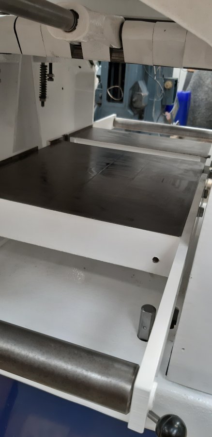
The thicknesser table is now mounted, and clocked at either end referenced off the cutter spindle. We are looking for less than 1 thou variance, which is far tighter than any new PT I’ve tested. The thicknesser table on this PT was not aligned with the spindle straight off and was out by approx 12 thou or circa 0.3mm over the 12” length of cut. To correct this we use shims under the table, between it and the column it sits on. In this case we added two 1 thou (25 micron) shims either side of a bolt to ensure it was properly seated. The radius we inserted them in at multiplies how much it tilts the table at either side. We usually use ‘calibrated’ beer cans that we cut up. It’s amazing how accurate beer cans are in wall thickness.
23F4F4F8-9DC2-4390-B9AD-FBF666AF0513.jpeg

Anyway, after a bit of adjustment (we’ll Sideways got it bang in first time……it’s not the first time he’s done it!)

619BC7E3-A58E-4EBE-A844-8C5A7298684A.jpeg

1DC92003-D79F-4A5B-B5BF-D277FFEFE204.jpeg


It’s about 1/2 thou of 12 microns or variance between the two ends……there is a theme starting 😂

Please pardon the dirty bits, they arn’t scratches etc just dirty hands. Sideways had been ‘feeding’ the tables with both Metalguard and liber on machine wax.
 
Last edited:
Next was assembly of the infeed and outfeed rollers. It’s easier to set everything up with them not in pace. We have to take the outfeed table off to fit the infeed roller and chip breaker.
A208DB2D-3325-43B6-BF25-66C65A0C9F64.jpeg


The chip breaker we normally mount after adding a couple of washers underneath it to raise it slightly. Every single machine I’ve done has needed this, and indeed when we took it apart it had the washers installed.

130A04EE-2E2F-4064-B8A8-48302B37CD28.jpeg

The next job will be to setup the height of the infeed and outfeed rollers as well as adjusting the spring tension.
 
Table back on and it's starting to look something like.
20220526_175612.jpg


20220526_175552.jpg


20220526_175644.jpg


20220526_175703.jpg

Notice the gap in the thickness table. This model has a roller in line with the cutter block to reduce friction while feeding. We haven't dropped this in just yet but it has height adjustments at each end so that the roller can be levelled to the table.
 

Attachments

  • 20220526_175552.jpg
    20220526_175552.jpg
    60.1 KB · Views: 0
  • 20220526_175607.jpg
    20220526_175607.jpg
    77.5 KB · Views: 0
  • 20220526_175612.jpg
    20220526_175612.jpg
    99.6 KB · Views: 0
  • 20220526_175644.jpg
    20220526_175644.jpg
    47.2 KB · Views: 0
  • 20220526_175703.jpg
    20220526_175703.jpg
    104.5 KB · Views: 0
Just a minor update - we didn't have much time to play yesterday.

The thickness table support / locking bar still had to be fitted and of course it turned out that there was overspray from the powder coat in the socket on the underside of the table. Cue half an hour of laborious hand work with a 20mm machine reamer to clean out the hole, then the bar slides up and in and is locked in place with a grub screw.

20220527_163632.jpg


20220527_163727.jpg


20220527_164115.jpg

As an aside - notice the two slots in the photos above ? One in the base casting and one above on the side casting ? Remember these for the future. They are there to create a route for the power cables from the bottom of the electrical starters that bolt onto the front of the machine and the two electric motors that are housed in the base. They keep the cable run nice and tidy as we'll see later on.

The scale was refitted on the planer table
20220527_165621.jpg


And pointer on the thicknesser.
20220527_165607.jpg


The original scale for this was damaged so a replica one will be created. We've had to do this before for my own first PT, so it won't be difficult.
 
Last edited:
Sideways, I am looking at buying a Sedgwick PT so I have been reading this thread very carefully and I must say it is a brilliant post (thank you). I have a couple of questions that I hope you can help clarify. Firstly, does the planer table height adjustment have any slack in or is it packed to a tolerance? for e.g. when you adjust the height what prevents the table from moving/twisting/left and right (even very small amounts) in the slots where the measurement scale is as this must impact on the relevant height WRT the blades?
You (or possibly Deema) also make reference that the model you are refurbishing has height adjustments on both infeed and outfeed tables and this is the best. I am a novice woodworker and can't really see why you would adjust the outfeed table once it has been set up - would you be kind enough and explain why you would perhaps want to adjust the outfeed table?
 
The cast iron sided pieces in which the slots sit that hood the table have two long bolts at the top that tie the two sides together. You adjust the tension on these bolts such that the tables will just slide smoothly. This minimises any ‘slop’ in the two tables.

Setting up standard blades can be difficult. For PTs that use standard knives and have a fixed out feed table you have to set each knife level and to a precise very accurate height. With a moveable out feed, you just need to set the knives level and at the same height, not to an exact precise height, as you can adjust the outfreed table. This makes setting up the knives a far simpler task.
 
I bought an MB new in January 1991. I'd visited the Sedgwick stand at the previous Woodmex, and quizzed the rep about their tolerances to do with planer bed alignments - you know, along, across, diagonal. He quoted something like 4 thou (of an inch). I thought that was fine.

But they must've built mine over the holiday period when they were all pineappled. The infeed / outfeed were bowed over the length, and the thickness table was skewed in the width by about 20 thou. Each table in itself was flat enough, it was the alignments. So the work it produced wasn't good. But what to do? Send it back, all 7 cwt of it? Disruption & downtime.

I decided to fix it - to make it mine, if you like. I filed the inclined ways to get the top tables in synch. And shimmed the thickness table with some pieces of Sellotape tin.

And it served me well for the next 30 yrs. I made wooden extension tables for surfacing / edging, and with careful setting-up was able to edge-joint boards of dining table length or more without any further need for dressing with a hand plane. Planed tons of reclaimed pitch pine and cleaned up the clag afterwards.

It was from the end of the era that had the adjustable outfeed table.
 
The cast iron sided pieces in which the slots sit that hood the table have two long bolts at the top that tie the two sides together. You adjust the tension on these bolts such that the tables will just slide smoothly. This minimises any ‘slop’ in the two tables.

Setting up standard blades can be difficult. For PTs that use standard knives and have a fixed out feed table you have to set each knife level and to a precise very accurate height. With a moveable out feed, you just need to set the knives level and at the same height, not to an exact precise height, as you can adjust the outfreed table. This makes setting up the knives a far simpler task.
Deema, Many thanks that makes perfect sense.
 
Quick question, is the scale for the planer table adjustable at all? Mines not accurate, it doesn't really bother me but would be nice if it was a bit better. I have only looked at it quickly and there didn't look an obvious way to do it, looked riveted on rather than being able to just loosen screws and move it on elongated holes or something?
 
@Doug71 I’m not sure what you exactly mean about accuracy of the scale, however, I’m interpreting it that the zero position on the scale doesn’t align with zero cut. Or alternatively say a 1mm cut isn’t 1mm.
I’m assuming you have standard blades in your machine……ignore the following if not. So to improve the accuracy is a fairly easy exercise if you have a clock on a stand or with a good straight edge. Set the infeed table to zero on the scale. Now adjust the height of the outfeed table to be exactly level with the infeed table and that they are both coplaner in all directions. Now reset the blade height. Your all good, it’s calibrated.

Yes the zero isn't zero but no I don't have standard blades, I use the ESTA type blades and carriers, I did wonder if this might be the problem. I hoped there might be an easy way to adjust the scale to allow for this.
 
@Doug71 again, an assumption you are using the ‘lugs’ on the Esta carriers to set the knife depth. Usually this means that the knives are too low for the zero to be on zero and starts at say 1~2mm. I set the carriers to sit on the two height setting grub screws and use a none permanent thread lock to make sure they remain set. This allows them to be set with the infeed table on zero. They then still drop in without the need to setup. I prefer to keep as much of the table slides inside the slots for rigidity.

the scale is held on by hammer rivets, they can be removed with care. You can then either file the holes in the scale into slots, or just glue it down where you want it as an alternative.
 
@deema yes you are correct I use the lugs on the carriers to set the knife depth and my scale does read about 1.5mm when it should be zero ( you do know your stuff don't you!).

I don't recall seeing any grub screws in my block but will take a look next time I'm swapping knives. When I got the planer it had standard blades in with some small wood packers under them, that must have been the method the previous owner used to set the knife height in the block 😐


Thank you for the advice, really helpful as always 👍
 
@Doug71 the grub screws (2 of) should be in the bottom at either end of the slot, may be missing and just need replacing. There is normally a recess to allow them to be adjusted with the blades loosely fitted……a feature I really like. If they need replacing make sure you use exactly the same length / style in all 4 holes. If one is missing, I’d replace them all with identical to ensure the spindle is balanced.
 
The press is used to remove the bushes that are in through holes, however there are two that are in blind holes. Normally blind hole pullers will get these out, however they were pushed in so far that the puller couldn’t get a grip. In these circumstances a bit of lateral thought is required. We used a 1” tap to act as a puller. You use tap to thread the bush and when the tap reaches the bottom of the hole it pushes up the bush!
View attachment 132429
Brilliant tip, thank You. I've not not come across this method before. What if the bush starts to spin though when it's still deep in the hole? Tony
 
It’s been while since @Sideways and I have been able to get together to work on the PT. Life has got in the way, but today we were able to make some progress. Firstly most of the rewiring has been completed. Sideways is going to improve the way it was originally wired, and we will show what has been done shortly.
Now that the Vertical shaper that is mounted on my Bridgeport clone mill is back up and running after a rather silly moment I had that blew up the motor; we were able to start and ‘play’ with it to work out how to use it. I have used a horizontal shaper briefly a long time agol but this is different. So, after a little experimenting and after advise from members on another thread on here we started to cut the key ways. The clapper box was made solid, ie it did not allow the tool to move back on the return stroke. It’s actually very easy to use and setup, which made a change!

I did take a video of it cutting the gear we have now completed. However it’s too big for the server to accept. I will video the next one…..for a shorter time and uplpad that when we do it, anyway, this is what it looked like after it was cut and then test fitted, a bit more work to do on it yet. There is a tapped hole for a grub to cut and the gear length needs shortening. However, we were delighted to have ‘mastered’ the shaper.🥴

BCD5196B-7D52-4E44-958A-AD824E9D07C7.jpeg
CADAB454-AE46-44C0-9707-FC0D3A020D06.jpeg
 
All three sprockets now have the key ways cut into them. A good learning curve with the vertical shaper, we discovered that the tool can come loose which is interesting🤯. We cleaned away the oil for the video, but normally we would have oil for the cuter to pickup as it cuts.
 
Last edited:
After the keyways are cut a hole is centre drilled, pilot drilled, drilled for the tap and tapped for a grub screw to hold the sprockets onto the shafts. The grub screw tapped hole has to align with the keyway.
We will make a temporary shaft with a key way cut into it to allow us to mount the sprockets on the lathe in order to turn the boss down to the right length. The OE sprockets are not very deep, and standard off the shelf sprockets need shortening.
C1631527-AC05-4BA9-8C87-EDA75C720899.jpeg
B6EC8AE3-C703-444F-9713-2E3272B169C0.jpeg
 
To finish off the larger sprockets the boss needs to be turning down in Diameter and shortening. First job was to make a quick arbour to mount the sprockets in in the lathe. This was just turning down the diameter to suit and milling a keyway into a bit of scrap.

676367CE-A745-47C2-A876-EE474E4D90E2.jpeg
 
Back
Top