How do I calculate these angles?

UKworkshop.co.uk

Help Support UKworkshop.co.uk:

This site may earn a commission from merchant affiliate links, including eBay, Amazon, and others.
Surprised that as an engineer you didn't know about these things J-G!
Of course I'm familiar with working directly with life size drawings - for projects of the scale of buildings and, more specifically, ships - where a error of (say) 5mm over 10m would amount to a change in the angle of 0.028648° or the 10m length being 10,000.00125mm! When you are dealing with 180mm and (again say) 5mm you are in a totally different situation.

I can appreciate that you can only offer an opinion based upon your own personal experience and when that amounts to only dealing with architectural scale objects your 'layout' may well suffice but I also have experience of working with clocks and watches where taking the liberty of being 0.01mm out is a failure!
 
Here's my drawing of the graphic setting out method, made it to fit my A4 scanner so smaller than our OP's design.
120mm square base, 100mm high, 20 mm thick timber, to make it easier to read and possibly to understand!
Would work similarly with different dimensions.
My drawing shows the square plan in pink and the plan of one of the triangular sides in pink, as though folded out flat.
In fact "folding out flat" is the key to the whole process in general
The green lines are the inner face and hence are the gauge lines for the bevels.
Transfer the lines to the workpiece and the pink and green triangles are all you need to make the thing; by hand working to the lines or by machine setting to cut bevels to meet the lines.
The only measurements put in are the base and height, all else is worked up on the drawing.
No need to measure any angles or even to know what they are as the workpieces are marked up with lines taken from the drawing, with dividers etc. and marking gauges. Two needed as there are two marking gauge settings
Quite easy to do but will confess it took a bit of revision - I thought there’d be an example in one of the books but they are all much more complicated!
I could attempt to explain how it’s done but I think this would be really difficult unless doing it live, so I’m not going to bother!

View attachment 152614


I've used the method several times as written up on my website Making perfect trestles
I’ve made a few of these over the years, with variations, including a big brother of the lathe stand shown.
The setting out in the book (Joinery and Carpentry Vol 4 Greenhalgh, Richard (ed)) looks harder than it is, because it’s annotated all over, with construction lines and detailed explanations.
Once you’ve got the idea it goes quite easily with much less fuss.
What makes it hard to understand at first is that it would be easier to grasp as a set of 3 or 4 separate drawings, but in order to cross reference and avoid mistakes these are done over each other; developing the details from the plan and elevation put in first.
Hope that helps! :ROFLMAO:
I think this is fine if you want to construct a square frame with a triangular frame on top of it. What it is missing is the 'lean' (for want of a better word) where the triangles form the faces of the pyramid. The base and the sides will need to be cut at an angle and your drawing doesn't show those angles.
Me, I'd use a combination of sketching and trig to get the angles or just use one of the helpful calculators that Inspector posted.
 
Of course I'm familiar with working directly with life size drawings - for projects of the scale of buildings and, more specifically, ships - where a error of (say) 5mm over 10m would amount to a change in the angle of 0.028648° or the 10m length being 10,000.00125mm! When you are dealing with 180mm and (again say) 5mm you are in a totally different situation.
I'm talking about a very normal woodwork setting out technique which was widely used and taught, particularly for roofs and their components, until quite recently.
It's still very useful, and even more so for people who are bad at maths or don't want to fiddle about with Sketchup etc.

I can appreciate that you can only offer an opinion based upon your own personal experience
As you are too. On this I seem to have had more experience than yourself.
and when that amounts to only dealing with architectural scale objects your 'layout' may well suffice but I also have experience of working with clocks and watches where taking the liberty of being 0.01mm out is a failure!
Clocks and watches are not involved
 
Last edited:
I think this is fine if you want to construct a square frame with a triangular frame on top of it. What it is missing is the 'lean' (for want of a better word) where the triangles form the faces of the pyramid. The base and the sides will need to be cut at an angle and your drawing doesn't show those angles.
It can show the angles if required, but takes a short cut by just showing the gauge lines which would develop the angles. It means you don't have to measure angles or try to reproduce them - they come about of their own accord if you work to the lines
Me, I'd use a combination of sketching and trig to get the angles or just use one of the helpful calculators that Inspector posted.
No problem with that. I'm just reminding people of a useful alternative method.
There's a bit of a learning curve but it doesn't involve maths at all, except you need to be able to put in the basic dimensions, in this case the size of the base and the height. If you were copying an existing example you could do it by dividers etc and be completely ignorant of all numbers and angles!
 
Last edited:
By the usual process of trial and error, if necessary on a sacrificial marked up sample
Why use T & E when the time taken to get an accurate measurement is trivial? Get it right first time!
The marked up workpiece does. Not sure of the compound angle prob with a mitre saw but it would be possible to work out the angles from a drawing too, if preferred.
To 'work out the angles from a drawing' would need you to measure (ie. 'scale') the drawing which is prone to the highest errors - which side of a pencil line should be used? or should the datum be the centre of the line? Even then - if you can overcome the potential errors I've referenced - you have to resort to the maths to get the solution.

I now do all my design work on the PC (rather than a Drawing Board) but never ever take the dimensions from the PC Drawing. ALL my dimensions are calculated. For this particular project I used the PC drawing to determine the aproximate angle (which suggested 12.9°) simply for confirmation that my calculated value (12.921°) was in fact in the right 'ball-park'. - before you deride me for suggesing that working to 3dp is futile if you are working with wood - what if the material involved is Aluminium or Brass sheet or even an engineering plastic - Acetal, Delrin etc.

I've just worked out that measuring a 5mm long pencil line drawn with a 0.5mm lead and making the error of measuring to the 'wrong' side of the line would cause an error of 5.71°
 
Last edited:
On this I seem to have had more experience than yourself.
I'll concede that I haven't designed or built many roofs - I can only recall less than 5 in my lifetime (and only for 'out-buildings') - but I have at least studied Architecture (that was my original 'want to be') but also did an appreticeship as a Tool-maker and have made clocks & watches as a hobby. I suggest that my breadth of experience gives me a right to an opinion.
 
I'll concede that I haven't designed or built many roofs - I can only recall less than 5 in my lifetime (and only for 'out-buildings') - but I have at least studied Architecture (that was my original 'want to be') but also did an appreticeship as a Tool-maker and have made clocks & watches as a hobby. I suggest that my breadth of experience gives me a right to an opinion.
Some competitive bragging going on here!
Nobody said you didn't have a right to an opinion but that doesn't mean you are right!
I was an architectural student too! And worked in an office as arch. assistant. And done lots of work at all levels (literally) on building sites. And been making things for a living for 60 years. And was taught the drawing-board roof layout system on a C&G course - I've still got the notes!
Anyway that's enough of this.
You could read Joinery and Carpentry Vol 4 (Greenhalgh, Richard (ed) if you want to catch up but the examples are all much more difficult than Johnwa's pyramid.
I might have a go at Rewound's cone and see if it could be done graphically, I don't see why not. Make myself a wooden trumpet - blow my own!
 
Here's a link to another drawing method to establish dihedral angles, bevel cuts, and mitre settings to construct square or rectangular based pyramid structures. It supplements or is an additional drawing method to that illustrated by Jacob, which I have to admit that for some reason I've not seen before, but I'm assuming is just as valid, and perhaps better, it appearing to be simpler. In truth, I nowadays seldom draft out the answer to this technical 'challenge' by hand or with a CAD program: I turn to a speadsheet I have that spits out the answer for everything from a three sides 'pyramid' to I think up to a twelve sided pyramid. Slainte.
 
Here's a link to another drawing method to establish dihedral angles, bevel cuts, and mitre settings to construct square or rectangular based pyramid structures. It supplements or is an additional drawing method to that illustrated by Jacob, which I have to admit that for some reason I've not seen before, but I'm assuming is just as valid, and perhaps better, it appearing to be simpler. In truth, I nowadays seldom draft out the answer to this technical 'challenge' by hand or with a CAD program: I turn to a speadsheet I have that spits out the answer for everything from a three sides 'pyramid' to I think up to a twelve sided pyramid. Slainte.
It solves the same problems the same way but with a clearer layout, mainly thanks to the ridge which separates the hipped ends. Mine goes the extra step of working out the gauge lines for the bevels, rather than extracting the angles (dividing the dihedral by 2 etc) thereby avoiding angles altogether. Your's extracts the rafter 'seat' and 'plumb' cuts where knowing angles is probably unavoidable, but I bet there's a way! Mine has no rafters
I made mine up from scratch but if I'd seen your's first it would have been useful! e.g. I pivoted the hipped end from the eave, yours pivots from the ridge i.e. my pink triangle is the same as your hipped end red triangle. :unsure:
I might re-draw mine, its all interesting stuff!
 
Last edited:
Since posting the Blocklayer calculator in post 2 only resulted in it being reposted in post 15 and then acknowledged in post 20 it is obvious to me that what I post is just background clutter. I'll skip trying to be helpful in the future.

Pete
You were too quick of course no one believed you got it right after just the one post.
 
For those who like to do these things by paper and pencil here is the way to do it. It's quite simple and in theory you get an exact answer.
Here is our desired square pyramid:-

P1.JPG

The key is to find the angle between 2 adjacent faces. To do that we need 2 construction lines. Here in purple and at right angles to the adjacent faces:-

P2.JPG


What we are looking for is the true angle between the 2 purple lines
it can be done in 5 easy steps as follows:-
P4.JPG


1. Draw a side elevation of the pyramid

2. Draw the true shape of a side face

3. Draw the purple construction line from one base corner and at right angles to the opposite side

4. Draw a plan view of the pyramid. This is merely to get the diagonal length of the pyramid base

5. From each end of one of the diagonals draw 2 purple lines of the exact length from 3 above such that they intersect on the other diagonal.

The angle between these 2 purple lines is the true angle between the 2 adjacent pyramid faces. Note the 2 purple lines are not a plan view of the pyramid.

To get the bevel cutting angle take this angle away from 90º and divide by 2

I believe this method can be used for any regular upright pyramid, although for an odd number of sides a half diagonal and one purple line would have to be used.

Brian
 
For those who like to do these things by paper and pencil here is the way to do it. It's quite simple and in theory you get an exact answer.
Here is our desired square pyramid:-

View attachment 152653
The key is to find the angle between 2 adjacent faces. To do that we need 2 construction lines. Here in purple and at right angles to the adjacent faces:-

View attachment 152660


What we are looking for is the true angle between the 2 purple lines
it can be done in 5 easy steps as follows:-
View attachment 152657

1. Draw a side elevation of the pyramid

2. Draw the true shape of a side face

3. Draw the purple construction line from one base corner and at right angles to the opposite side

4. Draw a plan view of the pyramid. This is merely to get the diagonal length of the pyramid base

5. From each end of one of the diagonals draw 2 purple lines of the exact length from 3 above such that they intersect on the other diagonal.

The angle between these 2 purple lines is the true angle between the 2 adjacent pyramid faces. Note the 2 purple lines are not a plan view of the pyramid.

To get the bevel cutting angle take this angle away from 90º and divide by 2

I believe this method can be used for any regular upright pyramid, although for an odd number of sides a half diagonal and one purple line would have to be used.

Brian
Well yes that works.
Richards drawing and my drawing do exactly the same but in one drawing, which ensures that the parts all relate to each other on paper, which reduces error. So e.g.we both have your "true shape of the side" but laid out differently.... and so on.
If you look at a sequence like yours it's easier to grasp, but probably more error prone if you actually draw it up on a board.
And there are the other details - in my case to work out the gauge lines instead of measuring angles (no need to measure and halve the dihedral), in Richards to derive the rafter 'seat' and 'plumb' cuts.
Richard's "seat" cut is the same angle as my bottom edge bevel and the "plumb" cut given by the joining of the gauge lines (I think. :unsure: ).
I might have to lie down my mind is getting boggled!
PS it's interesting looking at these slightly different views of the same problem and solutions!
 
Last edited:
problems with drawings is, you would have to do it every time. Where as if you do the maths and esp if you embed the maths onto a spreadsheet then you can quickly recalculate. This is particularly useful if for instance you were needing to create a height and width and you only had wood of a certain width.

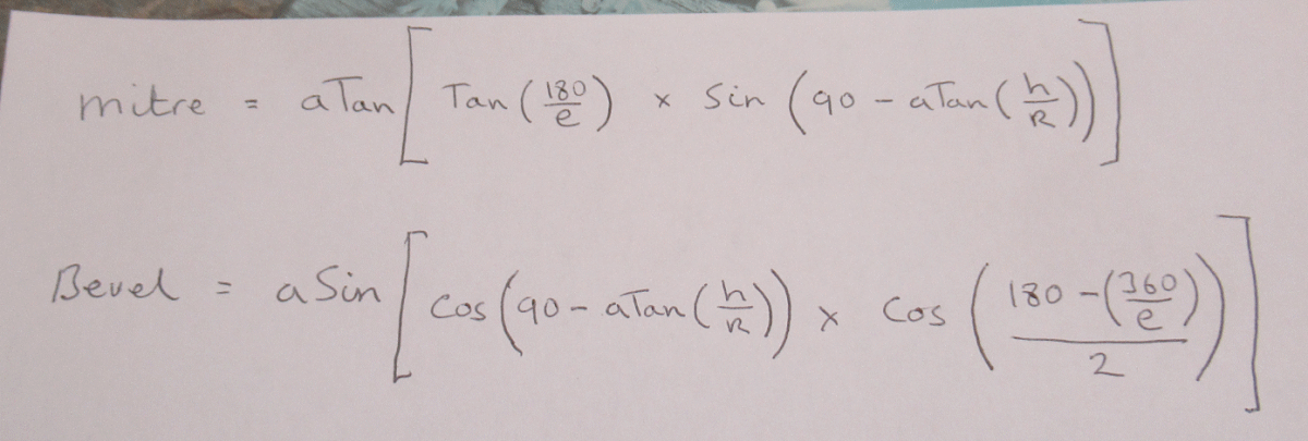
For whoever may be interested here is the formulas that I came up with for both the Mitre and the bevel.
the 3 variables that I have used are
e = the number of edges (4 sides, 7 sides 17 sides etc)
h = the overall height
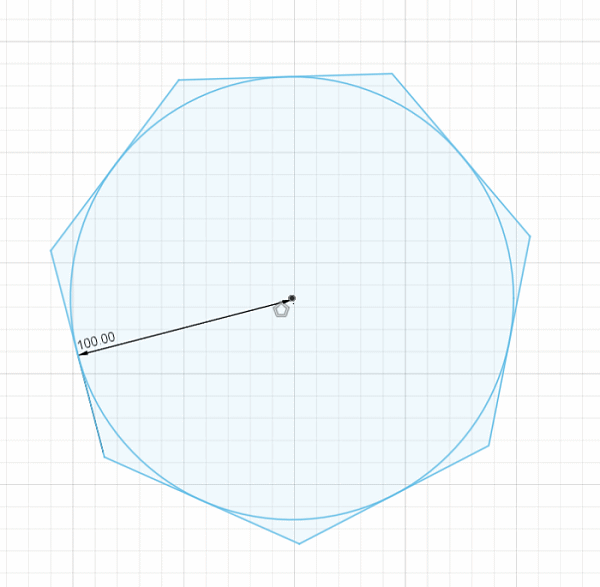
R = the Radius (imagine a circle drawn inside a polygon that meets the flats)(see image below)

xFormula.gif

x-Formula2.gif
 
J-G, in reply to your post saying that I am not responding to posts. I appear to have started a bit of a "sharpening" thread in that there have been many answers to my question, the majority showing different solutions and some not answering the question at all. I have responded earlier on in the thread to the members answers to my question by saying " thank you and that I will have a go at using the available online pyramid calculators as recommended by members."
So gentlemen, I say thank you all for your replies to my question, I will read through the posts and try to figure out a manual method of calculating said angles and meanwhile use an online calculator. I do hope this clears up any accusation of rudeness on my part, I was not being rude, simply as there were so many replies I responded and then let the thread run its course then go over all the replies later. Oh by the way, I have been in hospital. Maybe that could account for my assumed tardiness
 
problems with drawings is, you would have to do it every time.
Same with the maths! Not only would you need to understand it you'd have to be very competent with a calculator - a small error could put you miles out, and you'd have to work out different formulae for different problems. But if it works for you... etc.
The drawing could avoid the formula and be a half way solution - you could draw it out schematically and then from the known dimensions and angles work out the others one at a time, by trig/calculator
 
Last edited:
......I was not being rude, ...
Didn't cross my mind. Nothing to apologise for.
You just happened to hit on an interesting topic and it's quite likely that nobody has said anything very helpful anyway! :ROFLMAO:
PS forget to say - my preferred solution to making your 180x30mm rooflet would be to make it from a single solid piece. Not because it's the "best" way to do it but because it's something I know I could do easily and quickly, having done a lot of fielded panels in the past.
 
Last edited:
Just spotted this: A look through Euclid’s Door
Sounds like geometry might be coming back into fashion!
Haven't seen the book but my first thoughts are that maybe the emphasis is too much on the tools and not enough on the power of geometry as a non-numerical calculator.
Do they mention roof geometry at all?
Be interested to see it, but not at £31.50 (nc P&P)!
PS this looks interesting Artisan Geometry – By Hand & Eye Online
I tend to ignore Lost Art Press etc as they make such a song and dance of everything, not to mention over-produced and expensive books!
PS more reading! Numbers Versus True..... Sections and Projections maybe some catching up to do!
 
Last edited:
The Egyptians built pyramids over 4000 years ago. A square at the base was easy to measure. But did they (a) work out the angle of the sides for a particular height, (b) build a scale model, or (c) simply go upwards until reaching the top was inevitable - only space for one stone block.

The spire, google informs me, first appeared in the 12th Century. I would personally doubt that geometry played a major part in its construction - but if the earliest examples were of a more human scale than the pyramids they may be based upon a simple framework with component dimensions taken as the construction progressed.

Today - as preceding posts demonstrate there are numerous ways to calculate pyramidal dimensions. The capacity to measure and machine to several decimal places was not available to either ancient or medieval craftsmen. Calculations to these levels of precision require cheap laptops and smartphone apps.

Why write the above - it is clear that the capacity to construct pyramidal structures has existed for '000's of years. Historically methods were applied which were adequate in the context of then contemporary design and construction.

We can now do with precision that which our predecessors estimated. The debate over drawing vs app is somewhat pointless. There is nothing wrong (sometimes even satisfying) with using time served methods in woodwork - eg: a pole lathe rather than Axminsters best, three phase thicknesser vs adze, or (dare I say it) Tormek vs oilstone.

But precise calculation using the technology we have at our disposal is IMHO the right way to go, no matter how interesting or absorbing alternative less precise methods may be.
 

Latest posts

Back
Top