Multico Tenoner Restoration

UKworkshop.co.uk

Help Support UKworkshop.co.uk:

This site may earn a commission from merchant affiliate links, including eBay, Amazon, and others.

katellwood

Established Member
Joined
2 Jan 2007
Messages
1,006
Reaction score
17
Location
Near Dartford, Kent
For those that may be interested I have just brought a Multico tenoner back from the brink

Here is a pictorial diary of the project

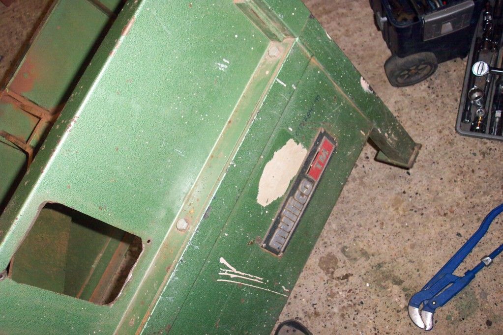
As bought
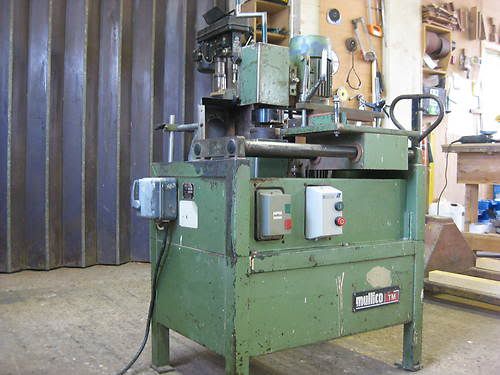
KGrHqZHJC4E8y0NYZBPU8pPIp7Q60_12.jpg


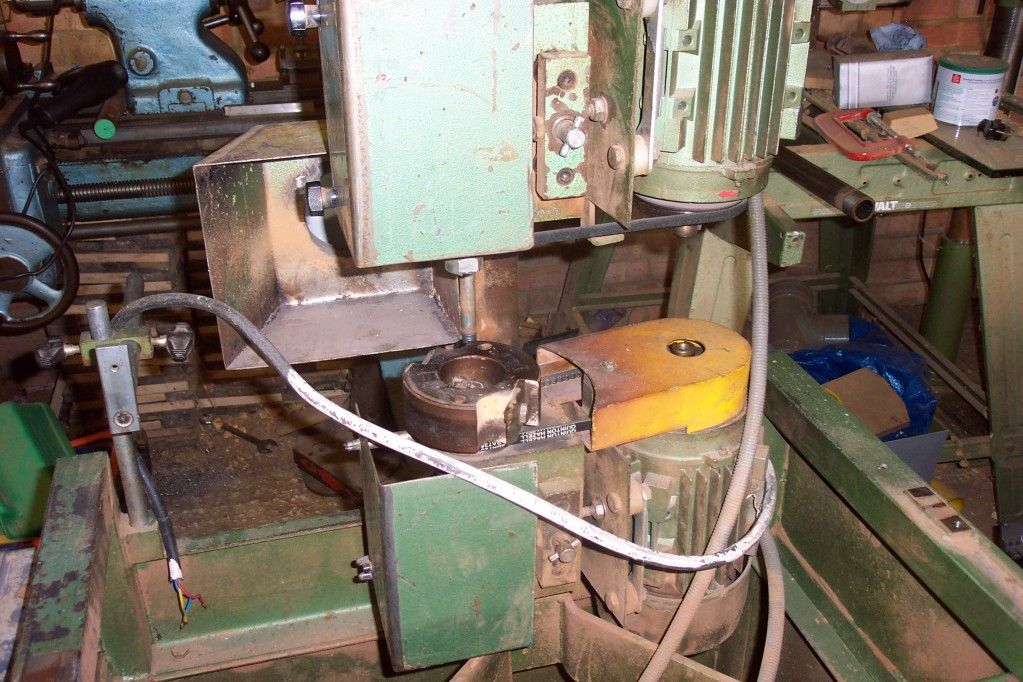
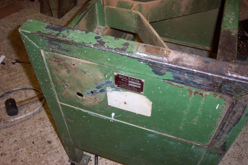
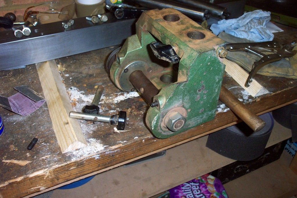
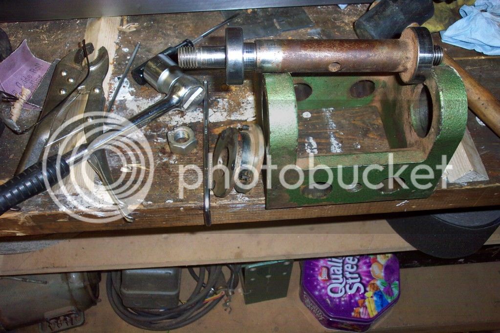
The stripdown

DCP_2407.jpg


DCP_2414.jpg


DCP_2408.jpg


DCP_2413.jpg


DCP_2409.jpg


DCP_2415-1.jpg


DCP_2416-1.jpg


DCP_2422.jpg


DCP_2423-1.jpg


DCP_2424-1.jpg


DCP_2426-1.jpg


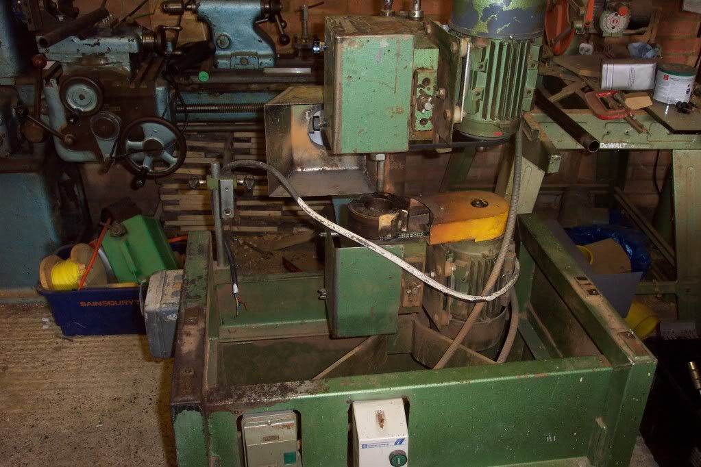
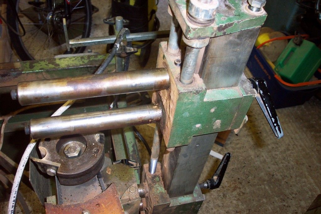
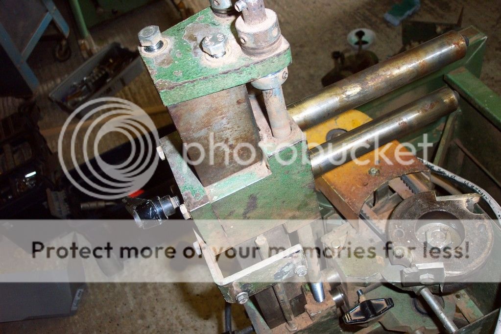
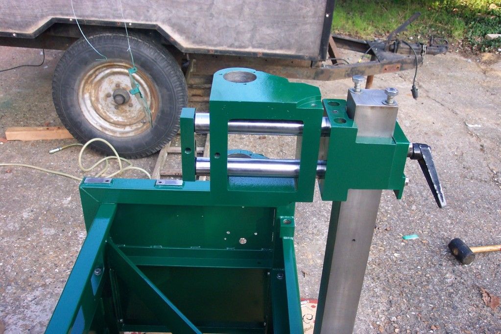
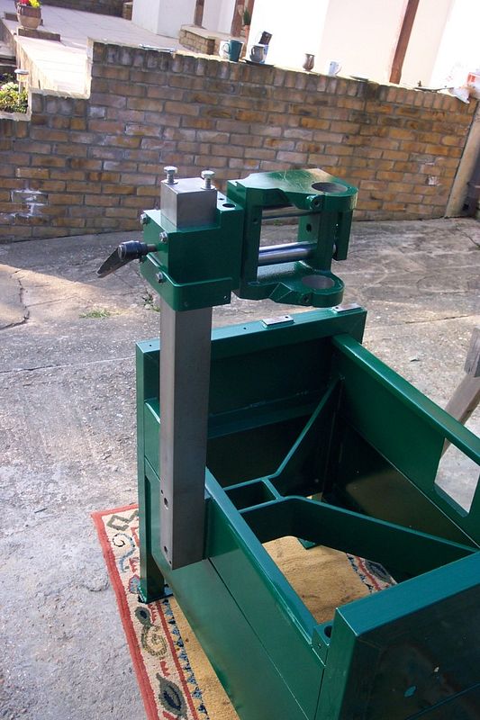
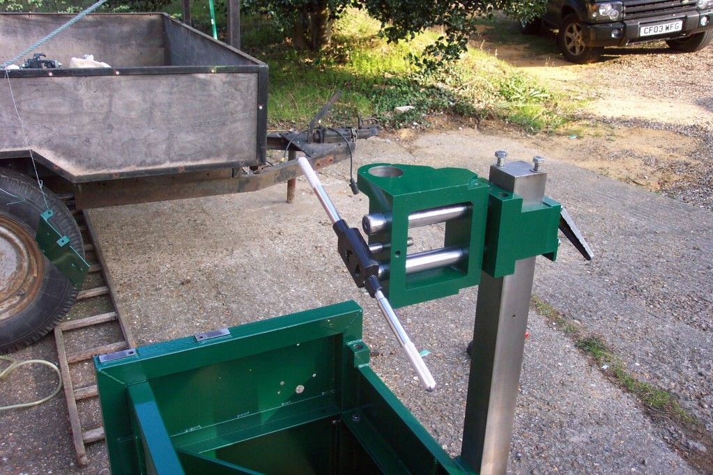
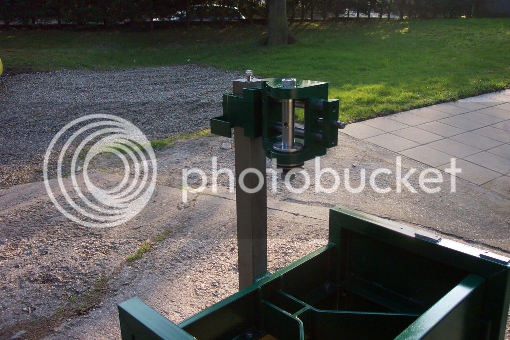
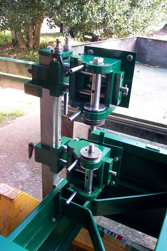
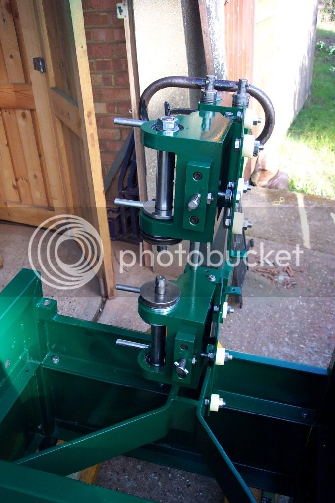
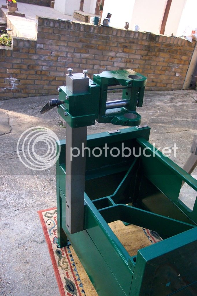
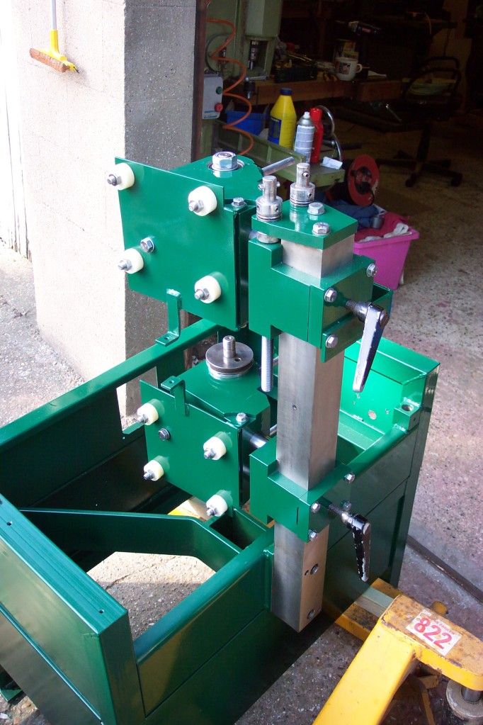
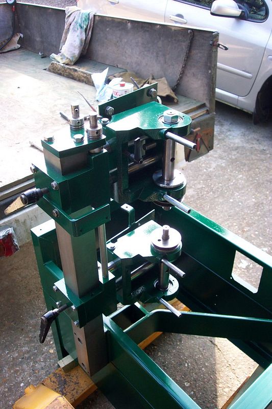
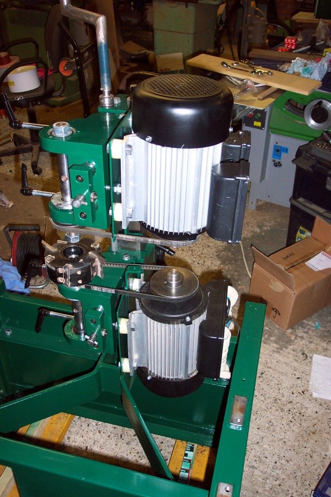
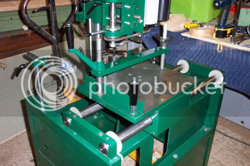
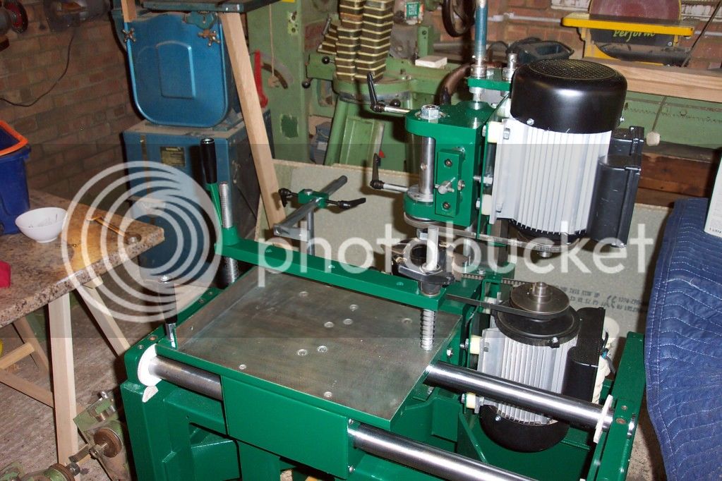
And following new bearings, solid steel bed bars, Bristol levers and paint the rebuild
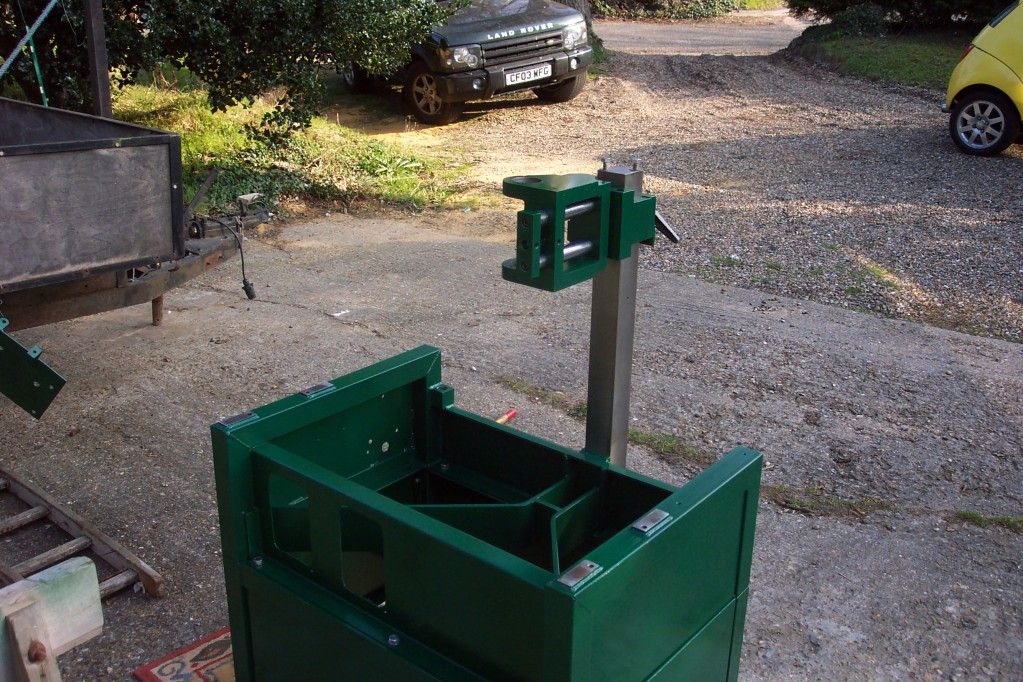
DCP_2427.jpg


DCP_2428.jpg


DCP_2430.jpg


DCP_2431.jpg


DCP_2432.jpg


DCP_2434.jpg


DCP_2435.jpg


DCP_2430-1.jpg


DCP_2436.jpg


DCP_2437.jpg


Two new single phase motors
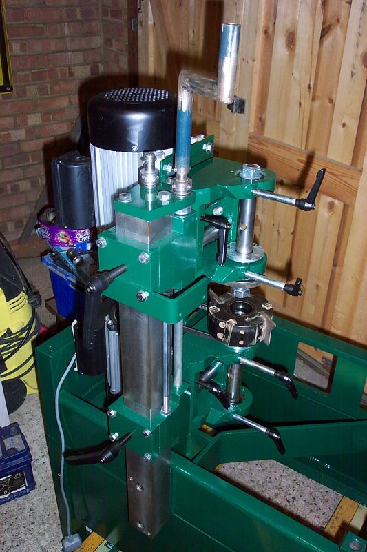
DCP_2438.jpg


DCP_2441-1.jpg


DCP_2443-1.jpg


DCP_2444-1.jpg


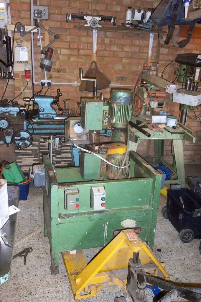
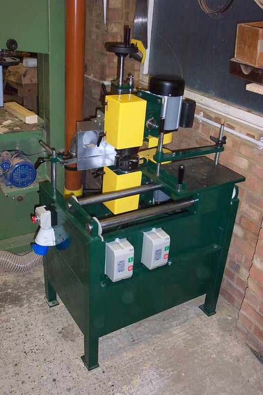
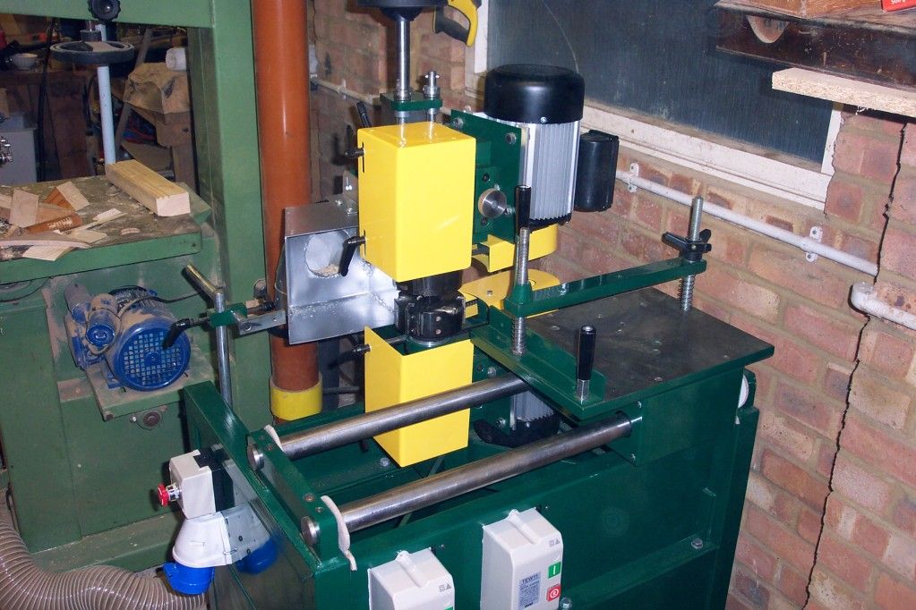
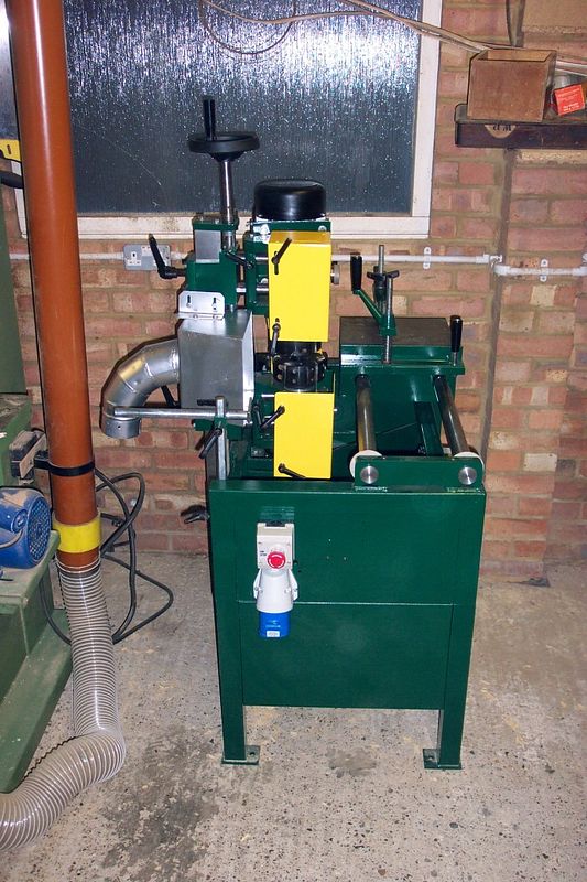
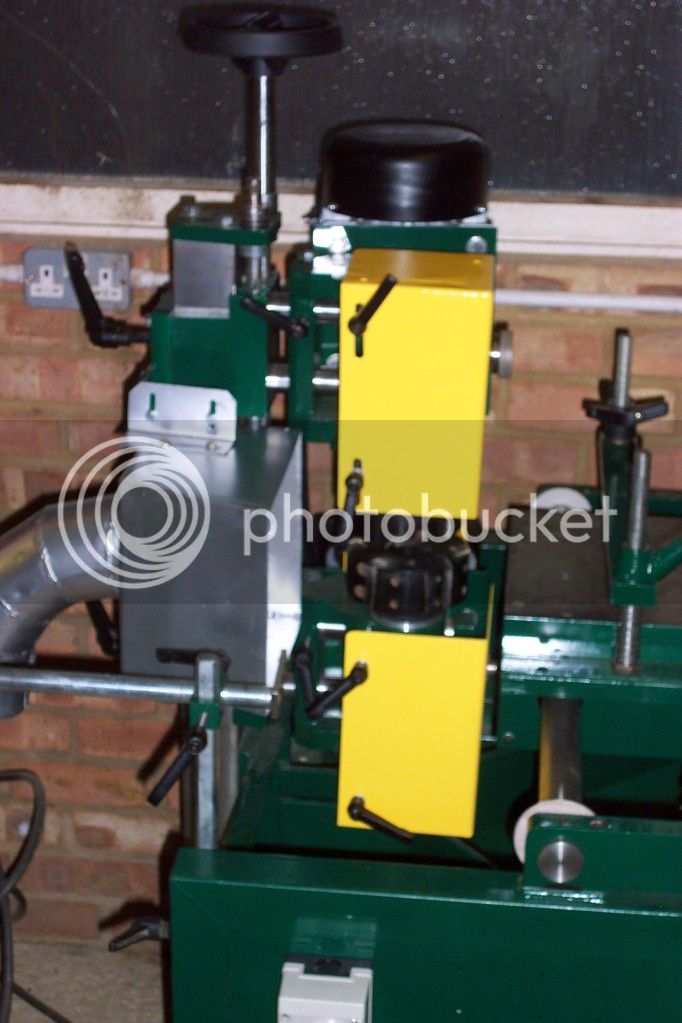
And the finished machine

DCP_2514.jpg


DCP_2515.jpg


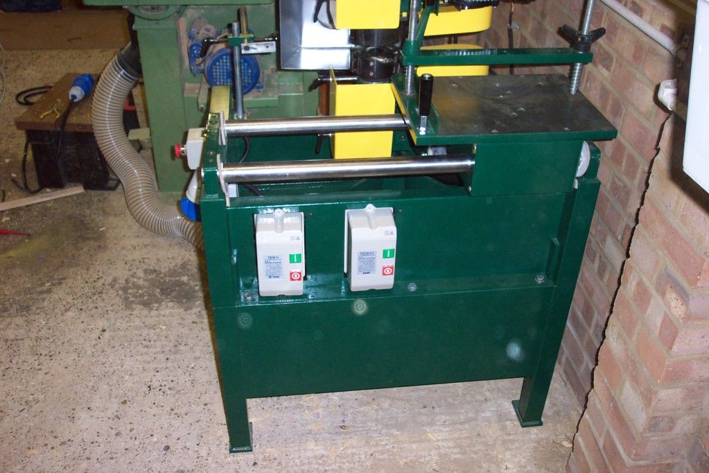
with new switchgear plus an emergency stop button
DCP_2516.jpg


DCP_2517.jpg


DCP_2525.jpg


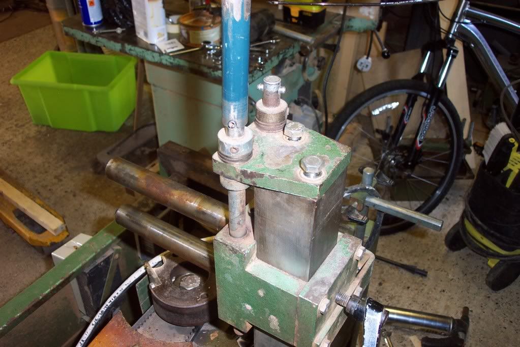
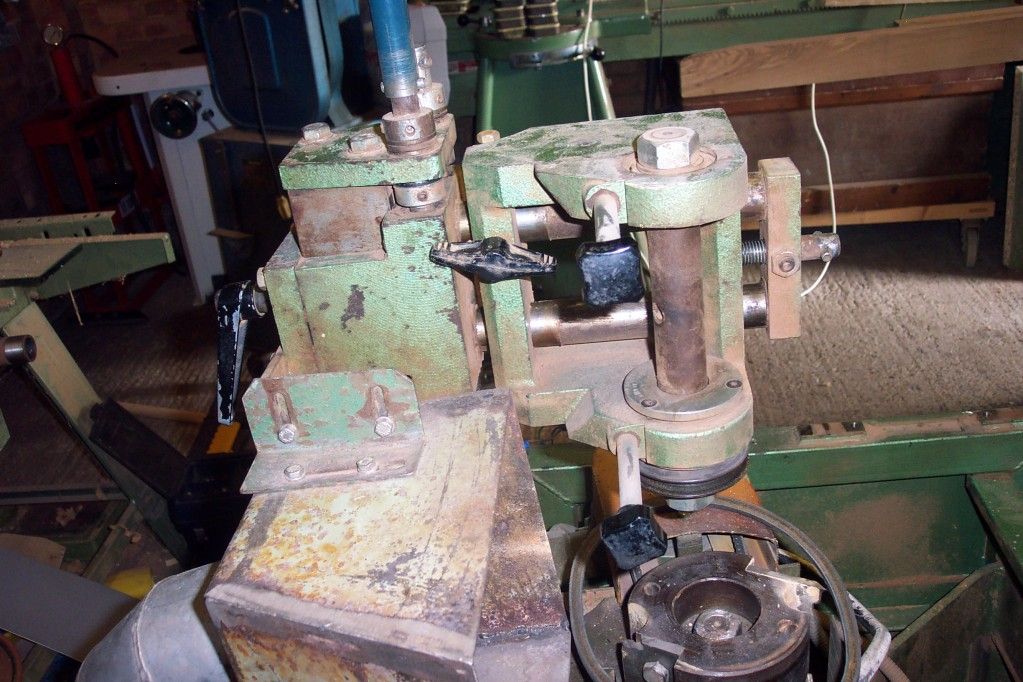
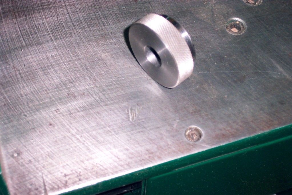
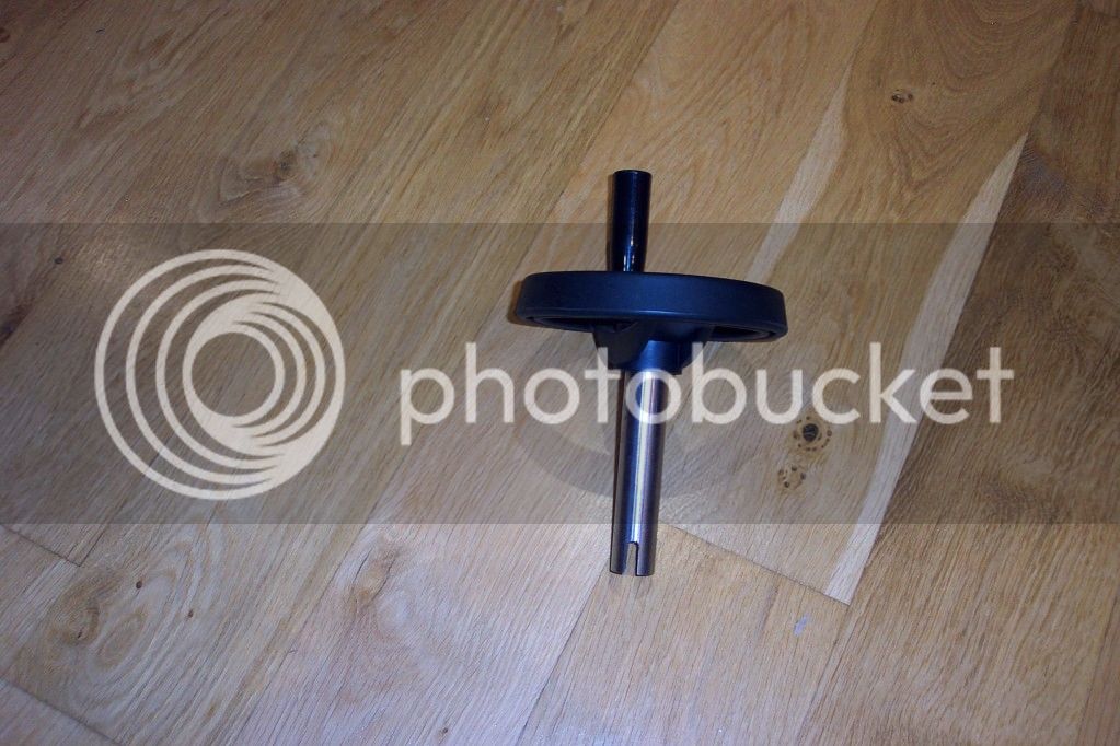
In addition these are a couple of parts I made for the machine which includes a new height adjuster
DCP_2519.jpg


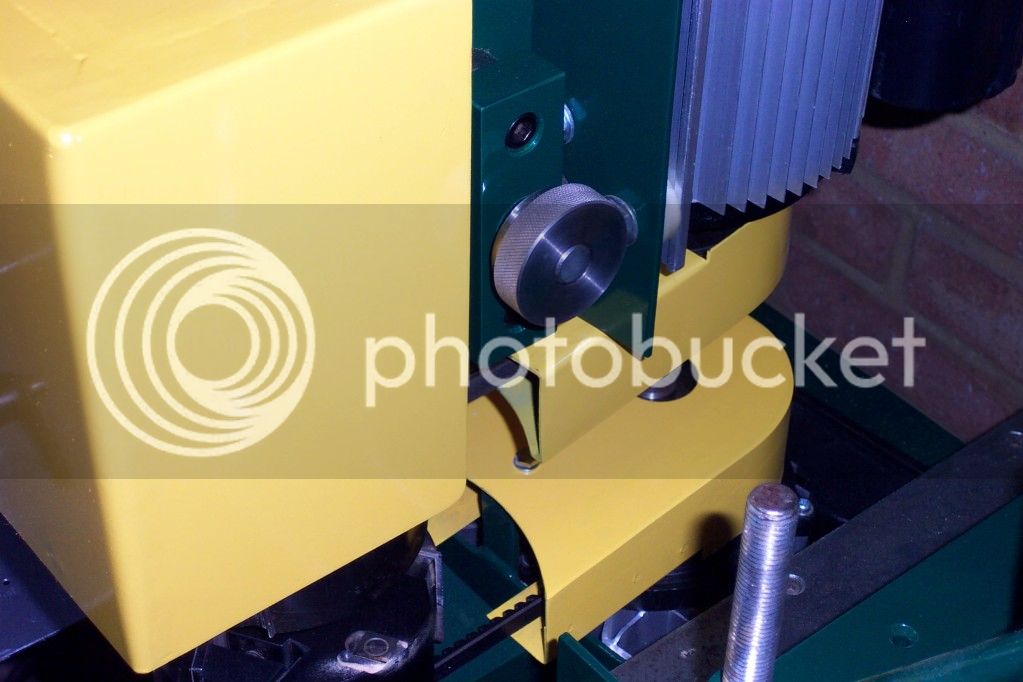
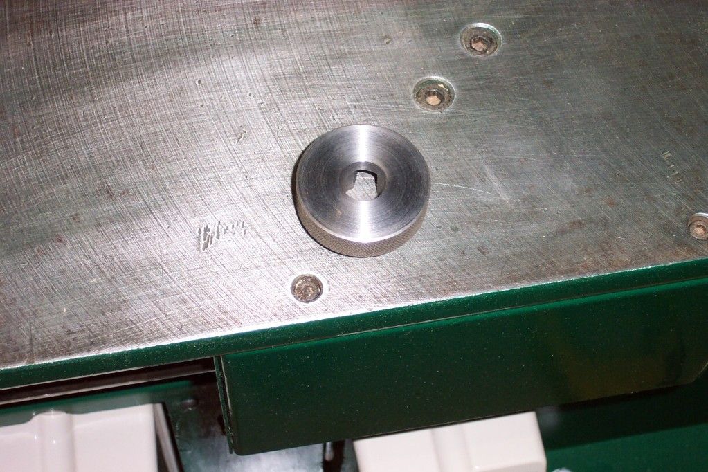
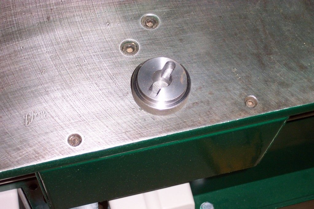
plus it would appear that the step shoulder adjustment is also adjusted with this same tool which especially for the bottom block was extremely hard to fit in around the sliding bed so I made this which works far better
DCP_2521.jpg


DCP_2522.jpg


DCP_2524.jpg


DCP_2520.jpg


The next item I intend to fabricate is a new extraction hood as the one fitted is not very efficient

Finally a big thanks to Bob (9fingers) who greatly assisted with a wiring diagram to wire the machine safely.
 
Nice job. That type of tenoner is scarce around here--most have two tenoning heads on horizontal shafts, then maybe two cope heads and a cutoff saw. Do you get much tearout on the back side or on the shoulders?

How powerful are the motors? Were the old ones burned out, or did you want more power, or just go to single phase?

Kirk
 
Lovely work, How are you planning on keeping shiny bits shiny. In the past I've used waxoyle but I've just got some T-9 spray to try
Mark
 
Hi Katellwood....

This is a very interesting restoration. Clearly you have opted for restoring the machine to a working condition with regard to precision and efficiency rather than originality and that is very valid indeed.

The fact that you have extended its life for many moons to come from the brink of the scrap yard is to be admired and I hope you have many years of use from it.

Wonderful job! =D>

Jimi
 
Guys thanks for the kind comments

SurreyHills":39kvtzuy said:
Wow - what a stunning job. Have you had chance to put it to work?

Not in anger, just cut some practice tenons


kirkpoore1":39kvtzuy said:
Nice job. That type of tenoner is scarce around here--most have two tenoning heads on horizontal shafts, then maybe two cope heads and a cutoff saw. Do you get much tearout on the back side or on the shoulders?

How powerful are the motors? Were the old ones burned out, or did you want more power, or just go to single phase?

Kirk

Kirk

Re tearout, a sacrificial piece will be screwed to the fence for each tenon following setup this I am assured should minimise tearout however should i be carrying out really accurate work I may cut the shoulders on the RAS first then use this machine to cut the cheeks

The motors are both 3hp single phase purchased from Axminster (I already had one motor which I had found in the bargain room at their sittingborne shop it only had a couple of bent cooling fins and were easily bent back with the aid of some really wide jaws on a set of welders mole grips)

The old motors I'm assuming were in good condition and considered purchasing an inverter or converter however as they were 3hp as well and there were two I would have needed a converter for at least 6hp (or a bit less if started individually) or two 3hp inverters the purchase of one moter to go with the one already owned was the best and most economical option. In addition I have put one of these motors on an old Wadkin ags10 saw which has turned it into an excellent machine.

Harbo":39kvtzuy said:
Fantastic restoration - how long did it take?

Rod

it has been completed over a period of approx 3 months however I would estimate approx 30-40 hours work, the hardest job was rassing off all the original paint for which I used an angle grinder with wire wheels, also in addition I has to fabricate one of the belt guards as one was missing, this was my first experience in mig welding thin steel. all went well and with using a little bit of car body filler after grinding down the welds looked exactly the same as the one already owned

wallace":39kvtzuy said:
Lovely work, How are you planning on keeping shiny bits shiny. In the past I've used waxoyle but I've just got some T-9 spray to try
Mark

Wallace, thanks for the suggestions, for the bed bars I managed to purchase some 75mm felt furniture floor protectors and with a bit of one of the original bedbars (which were tubing) I turned a small bit into a punch on the lathe I then punched a hole in four of these and placed them on the bedbars either side of the sliding saddle they are a tight fit, I have now calibrated the saddle with dial guages and a magnetic mount. I then intend to peel off the glue protectors and glue them either side of the saddle. As they are felt from time to time I intend to feed the felt with a little oil (what kind I do not know yet so suggestions will be more than welcome) and in use the bedbars should not rust as they should end up self lubricating

jimi43":39kvtzuy said:
Hi Katellwood....

This is a very interesting restoration. Clearly you have opted for restoring the machine to a working condition with regard to precision and efficiency rather than originality and that is very valid indeed.

The fact that you have extended its life for many moons to come from the brink of the scrap yard is to be admired and I hope you have many years of use from it.

Wonderful job! =D>

Jimi

Jim,

Yes this machine is to use, I retire from my day job just after the Olympics and from there I intend to be carrying out a great deal more woodwork and who knows possibly more machine restoration, since purchasing an engineering lathe I find I love playing with metal just as much as wood.

Finally as already mentioned a huge thanks to 9fingers who's advice on switchgear, cable sizes and a wiring diagram has given the machine the finishing touches it deserves plus both motors stop in approx six seconds so PUWER compliant (I,m sure the originals were not)

Thanks again all

Chris
 
Fantastic, really good job!

Do the motors have braking to stop within 5 seconds? Or is that just the natural run down time?
 
Only too happy to have made a minor contribution Chris.
The whole job looks really good and should have a long life.

Congratulations on your retirement. I did it a bit over 3 years ago with no regrets
Retirement has been the best job I've ever had!

Bob
 
I'm interested to know how you access the bearings to adjust the angle of the surface of the table relative to the cutter blocks.
I cannot see how to achieve this.
Thanks
Phil
 
Hi

Just had a quick look, on the cutter side bed bar there are four bearings bolted to an aluminium bar which is bolted to the underside of the table, this aluminium bar has two faces milled at 45 degrees to the bed too which the bearings are mounted. These bearings are fixed (no adjustment). To facilitate tightening there is a cast bracket which runs perpendicular to the bed, down past the bed bar and holds another bearing. If I remember correctly this is adjusted by an eccentric shaft carrying the bearing which is locked in place by a bolt

On the opposite side there is another bracket which carries two bearings (one top one bottom) which are both adjusted with eccentric shafts thereby allowing the bed to be adjusted co-planar to the blocks

multico bed 1.jpg


To set the bed co-planar I sandwiched a piece of straight and parallel timber between the blocks so as not fouled by the scribes or cutters

I then used a vernier height gauge on various parts of the table to set the timber parallel, in addition as I moved the table forward and back and rotating the timber back and forth I got it all set parallel in numerous locations.

For info, they are a pig to get too.

Hope this helps.
 

Attachments

  • multico bed 1.jpg
    multico bed 1.jpg
    46 KB
Thanks for the response. My sliding table is different in construction from yours.
The table and sides are a single casting.
On the cutterblocks side are 2 pulley rollers on the top side of the round bar and one bearing on an eccentric shaft on the underside.
On the near side are a top and bottom eccentric-shafted bearings.
All are through bolted to the sides of the slider.
The problem I have is that there is not enough eccentricity in the shafts to allow enough adjustment. It appears that I would need to adjust the positions of the 2 pulleys.
I am loath to try moving the pulleys. It is not clear to me how to satisfactorily achieve this. Are they in fixed positions or are they too on eccentric shafts. I suspect the former. The drawings available from Scott and Sargeant are not at all helpful, even where legible, and the table structure depicted is dissimilar to mine.
At the moment, the easiest thing to do is to shim the blocks supporting the round bars.
If I had more time and skill I guess I could machine bolts with greater eccentricity or buy bearings fractionally bigger.
I would be interested to hear if others have come across this and how they solved it.
Phil
 
I have just given my TM a major overhaul and found that the 2 location dowels in the main bar had sheared off!
That explained why I still wasn't 100% happy with the set up.
While I was at it I made one of your Shoulder adjustment tools - much better !

Thanks, Merlin
 
Hello All.
I found this thread with a google search only yesterday and I'm so impressed with the forum that I've joined up.
I've been in woodwork all my life starting with a Yacht and Boatbuilding apprenticeship in 1975, I had always helped my Dad out with jobs before that. I've been doing bespoke joinery and high end cabinet making since about 1990 as well as a couple of forays back into boatbuilding.
I have set up a good workshop at home over the years to do my own thing and this has come into it's own since the beginning of this year when I was made redundant when the poor old duffer I worked for retired. I am now doing my best to earn a crust from it as one man band!

So to cut to the chase.. I have a lovely Multico TM2 with single phase motors, like the one that Katellwood has done such a lovely job on in this thread. Mid way through the current job one of the shaft bearings has started squealing and I would like to replace all 4 as soon as this job is done.. Only 12 more tenons to do, so fingers crossed it will last. I would like to do a fairly quick turn round with the bearing change as there is another job with LOTS of tenons after this one. I don't really have the luxury of knocking the bearings out to identify them before ordering new ones, So I am hoping that someone could kindly tell me the size please? Then I have to find a supplier that is still operating, any tips on that would be gratefully received too.. Thanks in advance.

Looking forward to getting involved with this forum, as I get some very interesting commissions.. I'll show you some when I get permission for photos.. :D
 
Mr Gazza":3iypdgr4 said:
…..... I'll show you some when I get permission for photos..

Welcome to the forum.
You can "Attach" images of a reasonable size (file wise) without restrictions if you wish to start a 'Show and Tell thread', it's only off site links that are subject to anti spam 3 post restriction.
 
Thanks Chas, I'll give it a go when I get a minute.

I've just discovered that the plate on my machine is stamped TM3. I always though the number was the number of heads, but no way this ever had three heads, so I'm thinking it refers to 3 phase or Single phase? I'm assuming that mine was originally 3 phase.
 
Back
Top