Help with reassembly of Metabo BAS317 bandsaw

UKworkshop.co.uk

Help Support UKworkshop.co.uk:

This site may earn a commission from merchant affiliate links, including eBay, Amazon, and others.

pauldarnell

Member
Joined
25 Jan 2016
Messages
7
Reaction score
0
Location
bordon
I am new to this forum and don't know if this is the correct board to post a request for help upon. Sorry if I am in the wrong place.

I have had a Metabo BAS 317 bandsaw for many productive years.

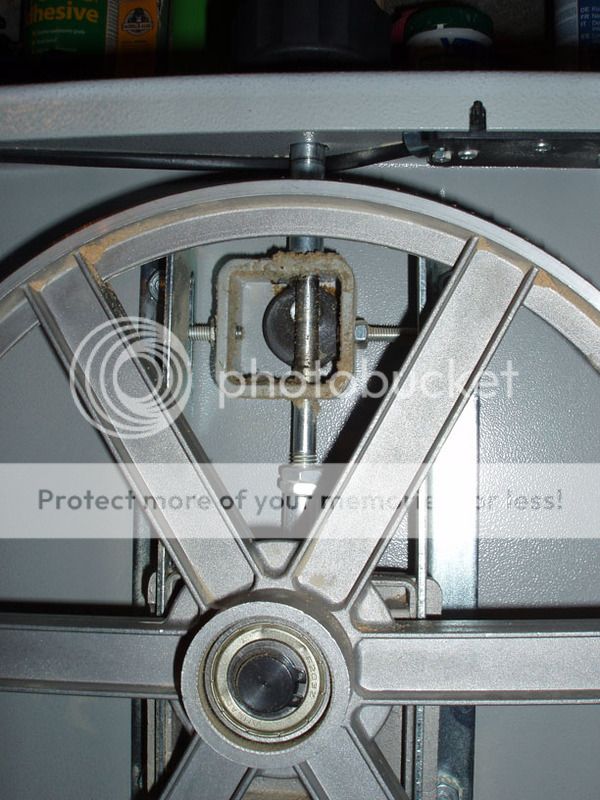
However, I have just recently replaced the top wheel axle assembly and can not get the blade tensioner to work.

I suspect I have a nut/washer/spacer in the wrong place on the adjustment rod assembly.

Does anyone have a picture of the top wheel assembly in working order so that I can compare with my setup?

Thanks for any help

Regards Paul
 
Paul
Welcome to the forum.
A picture of what you have would be very helpful, but you need a few posts here before the system will allow you to post a picture. You can either make a few dummy posts to get your count up (I think you need 5 or something small like that), or email me a photo and I'll put it up for you. If we can see what you have, we may be able to spot what's wrong.

Steve
 
Excellent offer from Steve, you can post pics when you have posted 3 replies and the pic sizing is on the page top, click forums above, then for sale, all the info is there. HTH Rodders
 
Gents

Thanks for the links to manuals etc... I had already checked them but to no avail - the assembly is just not shown in enough detail to ensure I have not misplaced a washer etc...

I have emailed Steve a JPG which will show the assembled tensioner which is not working.

If I turn the top adjuster the axle moves upwards correctly but the quick tensioner lever (the small box assembly with the cam inside) moves upwards but achieves nothing and therefore the blade will not tension.

Thanks for any help

Regards

Paul
 

Attachments

  • BAS 317 blade tensioner.jpg
    BAS 317 blade tensioner.jpg
    189.4 KB · Views: 93
Paul
Where is the wheel in all this? Is it mounted onto that black cylinder in the photo? If so. I don't understand your statement that the box achieves nothing when it moves upwards. If the box is moving and the wheel is attached to the box, then the blade must tension. Maybe not enough, if it is too long, for example, but it must tension, surely?
 
pauldarnell":21jzn6za said:
Gents
If I turn the top adjuster the axle moves upwards correctly but the quick tensioner lever (the small box assembly with the cam inside) moves upwards but achieves nothing and therefore the blade will not tension.
As I see it, when you lift or lower that quick tension lever, the cam MUST turn to operate the function. I would say, Here is the problem, cam not operating the box up or down, 'cos it's not going round to do so.
I suggest you watch the cam move within the box as the lever is moved, Either damaged splines or roll pin or maybe
even a locating square is causing this problem with the quick action tensioner not moving the cam action.
It's all joined so it must have some affect, that cam box will not move up or down but whole assembly and the axle will as an entirety.
Regards Rodders
 
Steve/Rodders

Thanks for looking into this for me.

When I operate the tensioning lever the cam operates and the small square box rises on the main rod.

However the box/cam is not secured to the rod and therefore it does not move the axle (black cylinder) and therefore does not tension the blade fully.

The main adjuster (large black knob/main rod) seems to operate properly moving the axle up to start the tensioning but without the final cam/box tensioning the blade will not fully tension.

I wondered if the 2nd large nut (marked in red) should be inside the box (marked in green) so that as the cam/box rises the axle will rise as well? However this is not shown in the exploded diagrams!

Regards

Paul
 

Attachments

  • BAS 317 blade tensioner 2.jpg
    BAS 317 blade tensioner 2.jpg
    198.1 KB · Views: 63
I'm afraid I still don't understand what is and isn't moving.

When you turn the knob, does the square frame move up or not? If not, what does move?

You may be right in thenking that those two nuts should be either side the bottom of that frame, but first I need to understand what is moving, and I'm afraid I don't.

Steve, bear of very little brain.
 
Sorry Steve I am not being very clear.

I have attached a new JPG that I hope makes it clearer.

When the large black knob is rotated the axle (marked with red X) moves up and down but this will not fully tension the blade.

To fully tension the blade I have to use the quick tension lever.

The small square box (marked with green X) with the cam is attached to the quick tension lever. It moves up and down when I operate the lever but is not connected to the main adjuster rod so the axle does not move at all. The 2 side bolts into the green X box are guides and can move in the slots of the side rails.

Thanks again for trying to help me.

Regards Paul
 

Attachments

  • BAS 317 blade tensioner 3.jpg
    BAS 317 blade tensioner 3.jpg
    196.3 KB · Views: 66
Ah, I see, I think.
Right, the cam is in the smaller top square, not in the bottom, correct?
In which case , yes, the cam box and the axle box must be connected, and at the mo they are not. Dismantle it and rearrange it so that there is a nut each side of the bottom of that top square frame. Then when the cam pulls that frame up, it will pull the axle frame, and thus the axle, up with it.
S
 
Steve Maskery":19uxpfgr said:
Ah, I see, I think.
Right, the cam is in the smaller top square, not in the bottom, correct?
In which case , yes, the cam box and the axle box must be connected, and at the mo they are not. Dismantle it and rearrange it so that there is a nut each side of the bottom of that top square frame. Then when the cam pulls that frame up, it will pull the axle frame, and thus the axle, up with it.
S

Yep, that should sort it :)

Tension the blade with the cam and lever engaged. The lever then allows you to release tension quickly and easily after use without disturbing the settings.

Cheers, Paul
 
Gents

Thank you for spending the time on this problem for me.

I will change it around tomorrow based on your advice (for about the ? time) and let you know how I get on.

Great forum - will explore and put some projects on the boards when I get time.

Regards Paul
 
I believe those two nuts should be locked together when the fast tensioner is used and the two nuts locked into place, just above the bottom of the top box,
I believe you set this pre tension by fitting the wheel and a saw blade, set the tension by the top knob and move the pair of lock nuts so as to make the cam "Snuggy" and pre tension lever "on",
as long as the boxes are free to move and slide up and down I say it will work.
Regards Rodders
 
Your assembly looks about right to me, here's my working one for comparison.

P1270332_1.jpg


The only thing that looks different is the amount of thread showing at the bottom, could the shaft be upside down ?

The tension cam works by pushing up the outer sleeve at the top, it is not attached.

If any more photo's will help let me know.
 
OK, how about this?
The two nuts lock against each other. Separate them, wind the rod further into the square frame to shorten the distance, then retighten the nuts. The threaded part will then appear lower down (edit!), as in ODS's picture.
 
Well done guys - it is now working fully.

The final solution was exactly as olddogsleeping/steve suggested - move the 2 locked nuts up the adjuster rod. This gives more blade adjustment so that I can fully tension the blade. The quick tension lever/cam/box then works on the top spacer as olddogsleeping said it would thereby adding more tension!

Great help guys - notably Steve, olddogsleeping, paulm and blackrodd.

My lesson for the future is take even more pictures before disassembling anything!

Hope I can be of help in future.

Thanks again Paul
 

Latest posts

Back
Top