Carpentry dilemma - Coped joint where both sides not horizon

UKworkshop.co.uk

Help Support UKworkshop.co.uk:

This site may earn a commission from merchant affiliate links, including eBay, Amazon, and others.

Bluekingfisher

Established Member
Joined
16 Mar 2009
Messages
1,524
Reaction score
8
Location
Land o' Burns.
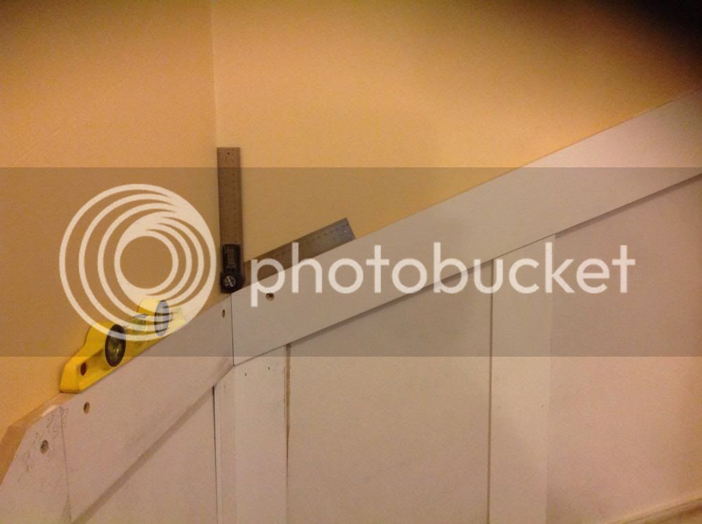
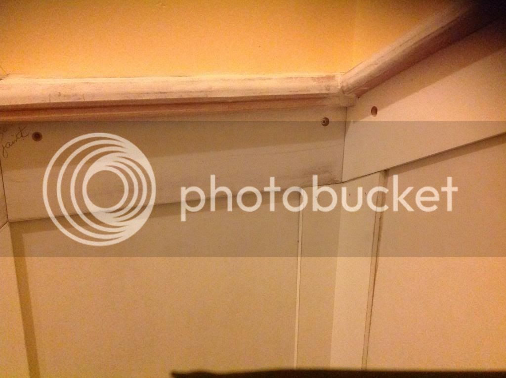
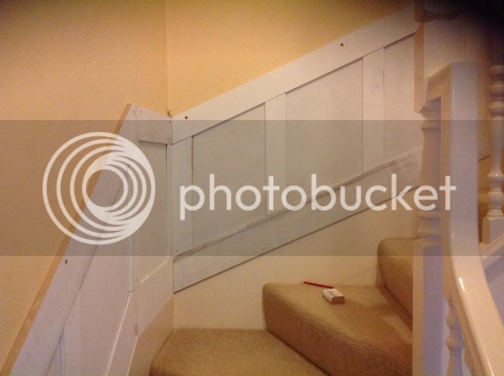
Gents/ladies I am currently installing wainscoting panelling on the stairs. Our stair is not a traditional straight affair, instead the stairs turn 180 degrees on themselves at the top from the bottom. This means that where the stairs turn 90 degrees from the level. However as the stair turns it raise 35 degrees from the horizontal.

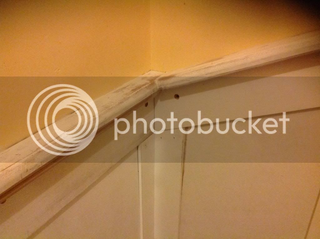
I am installing a 50mm chair rail/cap to the top of the panels. This is where I cannot for the life of me work out how to calculate the angles for the mating scribed joint.

I need to scribe the right angle joint where as mentioned one side of the joint raises 35 degrees from the horizontal plane.

I am not even sure I have described it correctly so will try to up load some photos

The last picture shows where my problem is. Hope the photos make more sense?

Any advice much appreciated
http://www.amazon.com/dp/B000P4JP66/
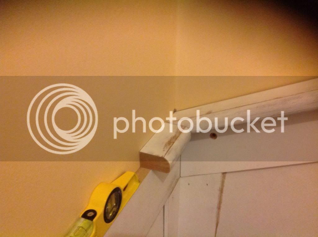


You need to increase the thickness if the rail under the chair rail to bring the chair rail up so that the bull nose at the edge of the horizontal section is level at the point where the radius blends into the top level with the piece that is running up the stairs. In this way you can run the horizontal piece through to the back wall, and joint the two sections together without any step.
 
Ok, I think I got it now, in this instance I need to raise the height or thicken the horizontal cap rail by 15mm. This of course may have an effect on the mating piece the other end of the horizontal rail?

Suck it and see I guess.

Cheers for now
 
would it look odd if u chamfered base of horizontal cap so it was inclined by the 35%

I guess maybe

Steve
 
I don't think it would look right if you thickened or inclined anything - you would make one end look right, but the other end would look wrong.

Looking at your last pic, I think I would run the capping on the horizontal part right through to the wall, then cut a sort of birdsmouth out of the part above it, so it sits neatly over the first bit.

Alternatively, if it's not too late, swap the capping for a smaller section where the flat part on the capping is the same width as the thickness of the boards on the walls. That way, the intersections would all be meetings of half cylinders, which would mitre properly. (I think I am imagining this right, but I may be entirely wrong!)
 
As Andy has said, run the horizontal piece through to the wall and then mason mitre/scribe the diagonal length into it
 
Hi

I'd go with Deema's method - there will be a small nib to fair in on the lower edge of the upper inclined section.

As long as the angle between the lower inclined and horizontal sections is bisected they will match.

Chair Rail.png


I may have missed something though

Regards Mick
 

Attachments

  • Chair Rail.png
    Chair Rail.png
    6.3 KB
Thinking about it again I think I misunderstood what Deema meant, and he's given the simplest method. Looking at the second picture, the top horizontal board, the one with the yellow level on, needs to be a bit wider, all along its length, so its upper surface is about 15mm higher. Then when the cap goes onto it, the curved part of the cap will coincide with the curved part of the cap on the sloping part that comes down to meet it.

At the open (left hand) end of this horizontal board, the corner where it meets the lower sloping part will have to move a bit but that is easy to patch.

The wider board will not look odd as it is covered by the cap and you can't get far enough away to see that it's wider.
 
I'm not sure if the pro carpenter would do it this way or if there were other factors to consider but it certainly was a learning curve and a little frustrating to say the least

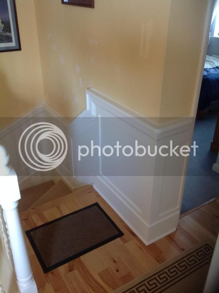
I took deemas advice and thickened the horizontal rail by 15mm by laminating a 9mm & 6mm strip of MDF which produced and exact height match form where I was able to make the masons mitre cut. It did result in the joint at the other end being a little bit belt and braces but I can shape the profile with a block plane When the adhesive has dried.

Considering it was an 8 foot length of cap rail, meeting the adjoining cap rail at the mid landing at an 11 degree angle it worked out ok, well certainly good enough for me and SWMBO seemed pleased enough,

I just need to add the a apron moulding beneath the cap rail and the trim moulding at the base where the base rails meet the stair string and it should look good with a couple of coats of paint.

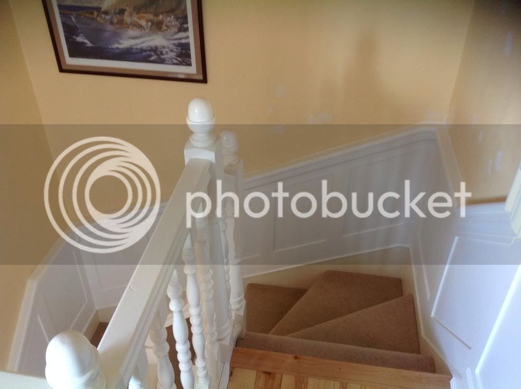
Thanks again for taking the time to offer advice, some extra pics added to see how it turned out.

David


Bluekingfisher you have the 90 degree corner as Deema had in mind but the joining of the cap at the rising rail and the vertical leaves a lot to be desired.
place the cap on the rising rail and put a pencil mark on the top of it then place the cap on top of the vertical and run it past the pencil mark on the wall,mark this with a pencil now where these two points meet you need to join it with the top point of the two rails.

This is called splitting the angle and will give you the angles to cut so that both pieces of stuff marry together at a perfect angle.
 
Billy - not sure I can decipher your method?

I am familiar with bisecting an angle but in this instance the rising cap would not allow for a flush fitting joint.
 
Dave in your last post with pics not the last pic but the next to last show the capping joining on the rising rail and the horizontal rail, that's where you have to split the angle.
 
Bluekingfisher":m0elqs0v said:
Gents/ladies I am currently installing wainscoting panelling on the stairs. Our stair is not a traditional straight affair, instead the stairs turn 180 degrees on themselves at the top from the bottom. This means that where the stairs turn 90 degrees from the level. However as the stair turns it raise 35 degrees from the horizontal.

I am installing a 50mm chair rail/cap to the top of the panels. This is where I cannot for the life of me work out how to calculate the angles for the mating scribed joint.

I need to scribe the right angle joint where as mentioned one side of the joint raises 35 degrees from the horizontal plane.

I am not even sure I have described it correctly so will try to up load some photos

The last picture shows where my problem is. Hope the photos make more sense?

Any advice much appreciated

http://www.amazon.com/dp/B000P4JP66/


Hi there. I applaud your efforts sir. I know from personal experience how difficult it can be fitting paneling to winders.
I often think it is helpful to visit period properties to see how they coped with similar situations.
This is how I got "round" the problem if you will excuse the pun :)
I think bringing elements back to a horizontal plane in the corners always makes things easier to deal with.

 
Dave go back to the post where spindel shows the drawing where he shows the packer that's what I'm talking about
 
Rich - I don't think I would like to have tackled the rounded corners you have completed, looks like very skilled work indeed.

Billy, I did use a packer. I used mine on the horizontal cap rail ( I think you may be able to see it on the latter picture I posted below?)


A few weeks. Ago I asked for some info on a coped cut where the mating cap rails were not meeting on the horizontal.
Well, I would just like to thank all those who offered their assistance.
It would appear that my efforts were not traditional, however I think it all turned out well.
After several weekends and 6 coats of paint it is now complete.
I just need to paint the walls and banisters as the new paint highlights the fact the walls have not been painted for a dozen years or more.
David


Billy Flitch":18o3ipax said:
Bluekingfisher you have the 90 degree corner as Deema had in mind but the joining of the cap at the rising rail and the vertical leaves a lot to be desired.
place the cap on the rising rail and put a pencil mark on the top of it then place the cap on top of the vertical and run it past the pencil mark on the wall,mark this with a pencil now where these two points meet you need to join it with the top point of the two rails.

This is called splitting the angle and will give you the angles to cut so that both pieces of stuff marry together at a perfect angle.

is this the bit u dont like bluekingfisher ?
image-12.jpg


Steve
 

Attachments

  • image-12.jpg
    image-12.jpg
    121.7 KB
Steve you have got it 100 percent right and I´m not beating on Dave just saying that joint is not right the way he shows it in his pic.
 
Bluekingfisher":2pto0o1o said:
Any advice much appreciated

http://www.amazon.com/dp/B000P4JP66/
All your problems stem from the layout of the rising panel (directly in front as viewed in your image) meeting the horizontal panel (on the left), and richarnold is pointing you in the right direction.

What I think you really needed was another horizontal turning right from the top edge of the horizontal left hand panel. This would feed into the rising panelling so that it looked a bit like this __/
With that configuration, and quite possibly another horizontal running return at the top of the rising panel to feed into the landing, or whatever is there, the mitreing and scribing tasks would have been relatively straightforward, although richarnold's sweeping chair rail configuration is an elegant solution.

As you've got it the best I think you can do is to work out a solution as neatly as you can, which you seem to be managing, unless you're willing to remove the existing rising panelling and replace it with a different configuration. Slainte.
 
Richard your quite right the answer to the problem would be to return the vertical rail around the corner then plumb it up to meet the rising rail then all the angles will pass. This happens all the time on stairs when fitting a chair rail and wainscot but that would normally be the answer on a 1/4 or 1/2 landing as we know this is a winder and it is JMHO that in this case this would look just a bit to clunky.

Richanold shows, how did you say Richard an elegant solution but to be perfectly honest I don't think that is going to happen here, you could talk about a Hunting miter but I don't think that will happen here either.

Deema has given IMO a perfectly simple answer to the problem but the joint where the bottom rising cap meets the horizontal cap has been executed wrongly and that is not an opinion but a fact. To say its ok when it is not would be wrong on our side.
Bluekingfisher said any advice much appreciated so it is up to us to show him what is right and what is not, having been shown then the choice is his how he does it.
 
Back
Top