


DavidE
Established Member
Hi all,
I'm sure many will be familiar with the "cyclone substitute" shown by Mike G. recently. I thought it was a rather good idea and started setting about making one on Sunday afternoon from various scraps lying around.
I decided to put a clear front on the top part of the "works" so I could gauge how effective it was and try to optimise it - in particular the baffle plates. I'm still working on this and will be attempting a few calcs this evening to try to review the design further. When I get the internals sorted I'll post a drawing with dimensions.
Anyway at the first pass I reckon it is about 98% efficient and is only letting the very fine dust pass. Hence the challenge to try to improve it further. The inlet gets a good swirling vortex going and with the increase in flow area this is where most of the dust drops out down the slide into the bin area.
These photos attempt to show the story so far. You'll notice some of the bits of wood round the baffles really are scrap bits and are not finalised yet!
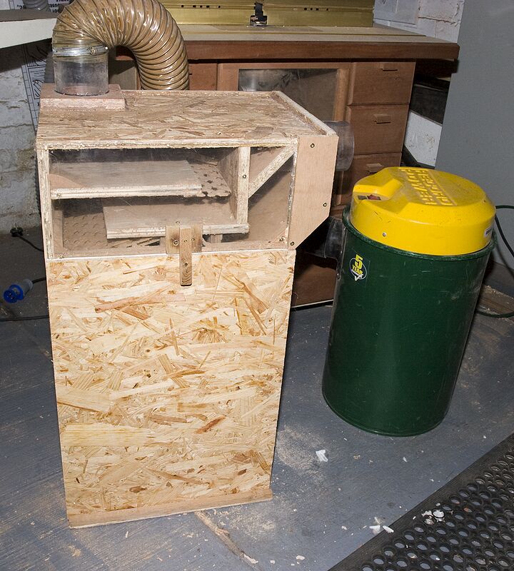
Overall view
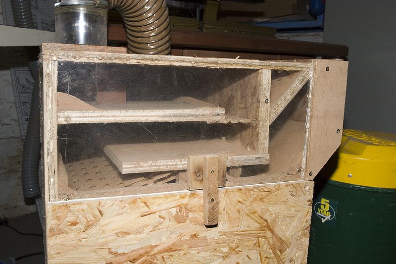
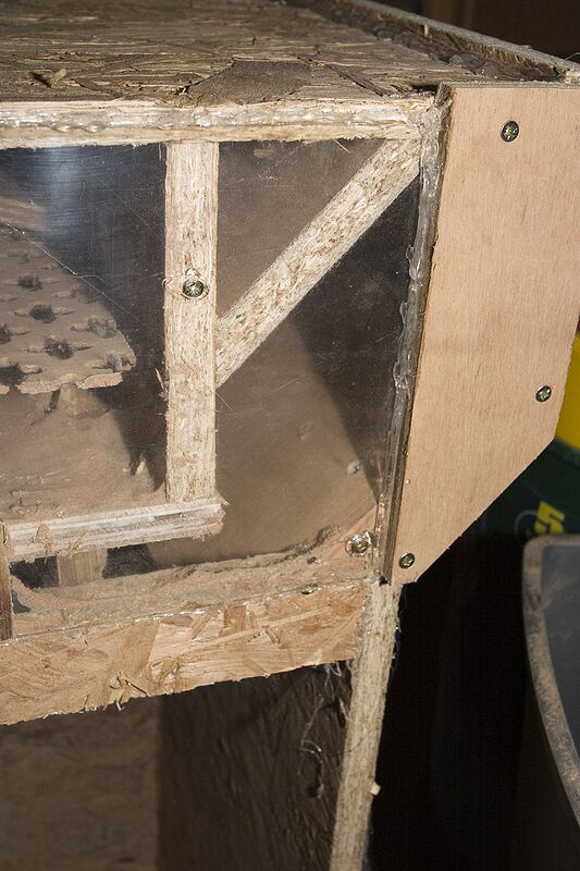
The gubbins
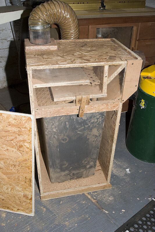
With the door off showing the bin - note the draught sealing strip and the slot at the bottom which the door sits in. The latch holds it quite tight and the extractor does the rest. When the baffles are sorted I will add some roofing underlay fabric or similar to guide the dust into the bin more.
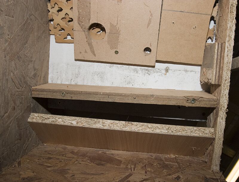
Looking up from the base.
Inlet area.
If you do make one make sure you anticipate sealing all the joins. I got through a few hot glue sticks to get it air tight. I'm going to paint it too as I think one of the OSB boards is slightly porus (it spent some time as a temporary floor and got a bit damp)
Please let me know if you have any suggestions for improvements.
I wouldn't hesistate to recommend making one - this was virtually zero cost and took a few hours to make - then I have been tweaking around trying to get that extra few percent. I've got quite a few ideas some I've tried and others are yet to be tried or are not needed. I did have an offcut of 4" soil pipe in the middle at one stage which was doing some interesting things and may be worthwhile pursuing further.
Cheers
David
PS thanks Mike!
I'm sure many will be familiar with the "cyclone substitute" shown by Mike G. recently. I thought it was a rather good idea and started setting about making one on Sunday afternoon from various scraps lying around.
I decided to put a clear front on the top part of the "works" so I could gauge how effective it was and try to optimise it - in particular the baffle plates. I'm still working on this and will be attempting a few calcs this evening to try to review the design further. When I get the internals sorted I'll post a drawing with dimensions.
Anyway at the first pass I reckon it is about 98% efficient and is only letting the very fine dust pass. Hence the challenge to try to improve it further. The inlet gets a good swirling vortex going and with the increase in flow area this is where most of the dust drops out down the slide into the bin area.
These photos attempt to show the story so far. You'll notice some of the bits of wood round the baffles really are scrap bits and are not finalised yet!
Overall view
The gubbins
With the door off showing the bin - note the draught sealing strip and the slot at the bottom which the door sits in. The latch holds it quite tight and the extractor does the rest. When the baffles are sorted I will add some roofing underlay fabric or similar to guide the dust into the bin more.
Looking up from the base.
Inlet area.
If you do make one make sure you anticipate sealing all the joins. I got through a few hot glue sticks to get it air tight. I'm going to paint it too as I think one of the OSB boards is slightly porus (it spent some time as a temporary floor and got a bit damp)
Please let me know if you have any suggestions for improvements.
I wouldn't hesistate to recommend making one - this was virtually zero cost and took a few hours to make - then I have been tweaking around trying to get that extra few percent. I've got quite a few ideas some I've tried and others are yet to be tried or are not needed. I did have an offcut of 4" soil pipe in the middle at one stage which was doing some interesting things and may be worthwhile pursuing further.
Cheers
David
PS thanks Mike!
 but it does look like the majority of the large debris at least is dropping.