You are using an out of date browser. It may not display this or other websites correctly.
You should upgrade or use an alternative browser.
You should upgrade or use an alternative browser.
The UKW Infill Project
- Thread starter jimi43
- Start date


Help Support UKworkshop.co.uk:
This site may earn a commission from merchant affiliate
links, including eBay, Amazon, and others.
tobytools
Established Member
Racers":1ie082vz said:You have a fine looking knob Jimmi :shock:
:wink:
Pete
=D> =D>
TT
You are doing a great job there.
I am enjoying the write up so keep it up.
Mick
I am enjoying the write up so keep it up.
Mick
Jimi - strongly recommend handturning brass. I have used carbon steel woodturning chisels, HSS, a reground 1/4" chisel and a clockmakers graver to good purpose. Negative rake is the order of the day and a fine finish can be achieved off the tool. Good for inside and outside curves and twiddly bits.
Thank you Andy for reminding me of "The Trustee from the Toolroom". I first read it a very long time ago but still remember some of the techniques described. Neville Shute either knew of which he wrote or listened very carefully to someone who did. Also the camaderie between people with a shared enthuisiasm.
Reminded me of many of the people on this forum.
Digressing somewhat, it is more than irritating when writers and TV get things wrong. A recent "Flog It" programme on woodworking tools was wrong more times than it was right, but an Australian author - Peter Temple - has one of his characters helping out in an old fashioned cabinet makers and seems to get both tools and techniques about right.
Keep up the masterwork, Jimi
Mike
jimi43
Established Member
There certainly seem to be a lot of tips coming out of this thread...by people adding their experience and from this we all benefit from new ideas...great stuff indeed!! Keep the ideas flowing!
Ok...leaving my knob out of the equation for the moment ...an update on today's work.
I have been discussing the iron setup with a number of people and getting some great advice but also this has given me a bit of a problem.
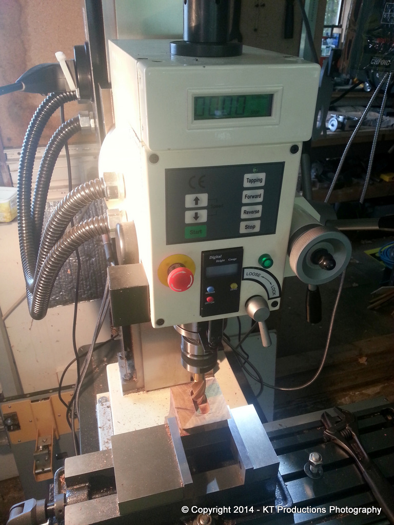
Whether we go for a single cut iron or a combination iron/cap iron setup is something I have been discussing offline...but either way I have now come to a decision point because if we choose the latter then we need a mortice in the bed. I was going to hold off but then I thought that it wouldn't hurt to just put a mortice in so that later on I can choose either at will. So..first thing to do today was to cut that mortice.
All was going well and then a setback!
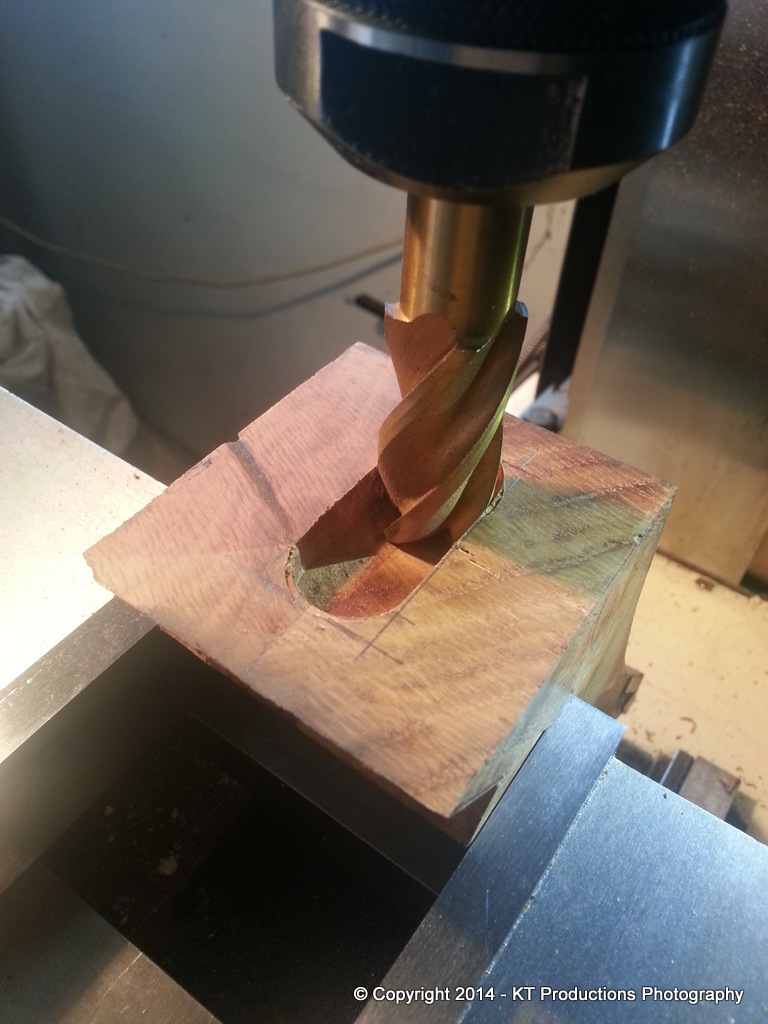
As I was approaching the breakout...I thought to myself...shall I stop now and cut the remaining piece by hand...and I wish I had done now. Ordinary wood would have been ok but I keep forgetting we are dealing with burr here and guess what...
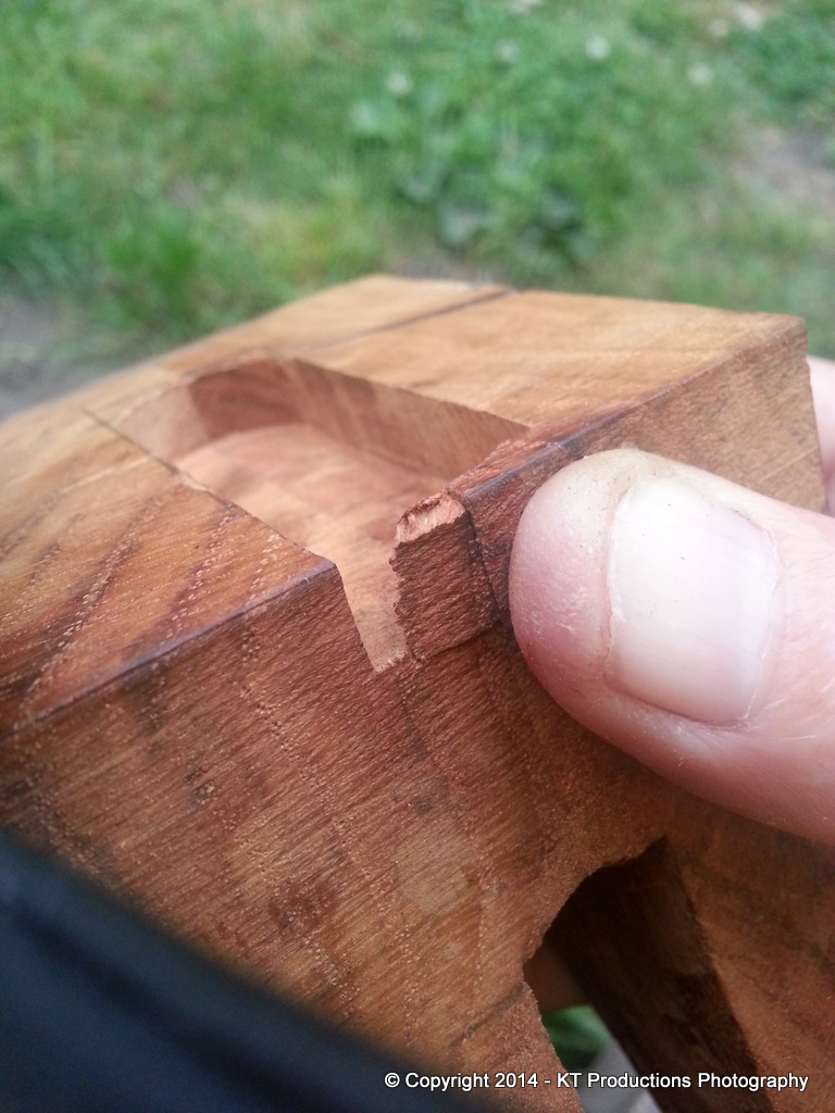
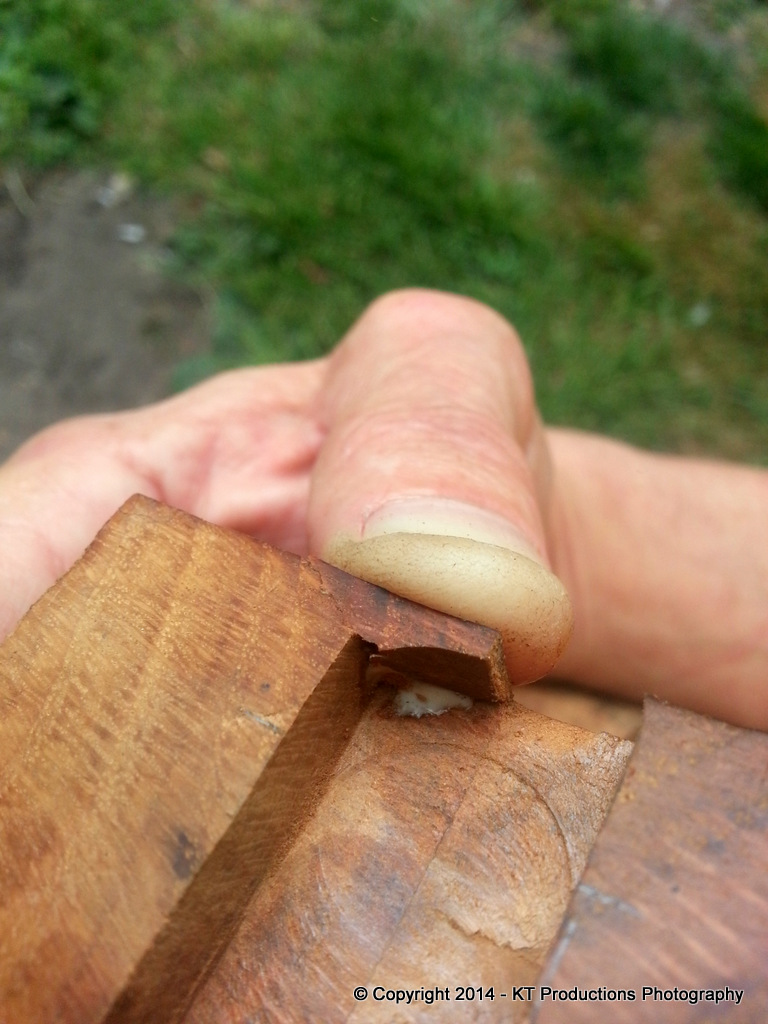
So...back to my restoration experience and out with the Titebond...and instead of having tomato soup with cheese and ham toastie being offered by Annie...I sat outside for half an hour and held the piece until it set up...
It'll be ok...this glue is better than the wood and it's hidden anyway but I was a bit annoyed for a brief moment!
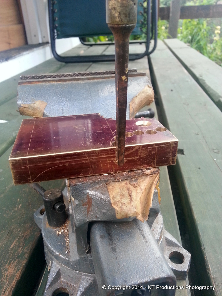
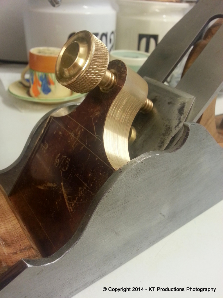
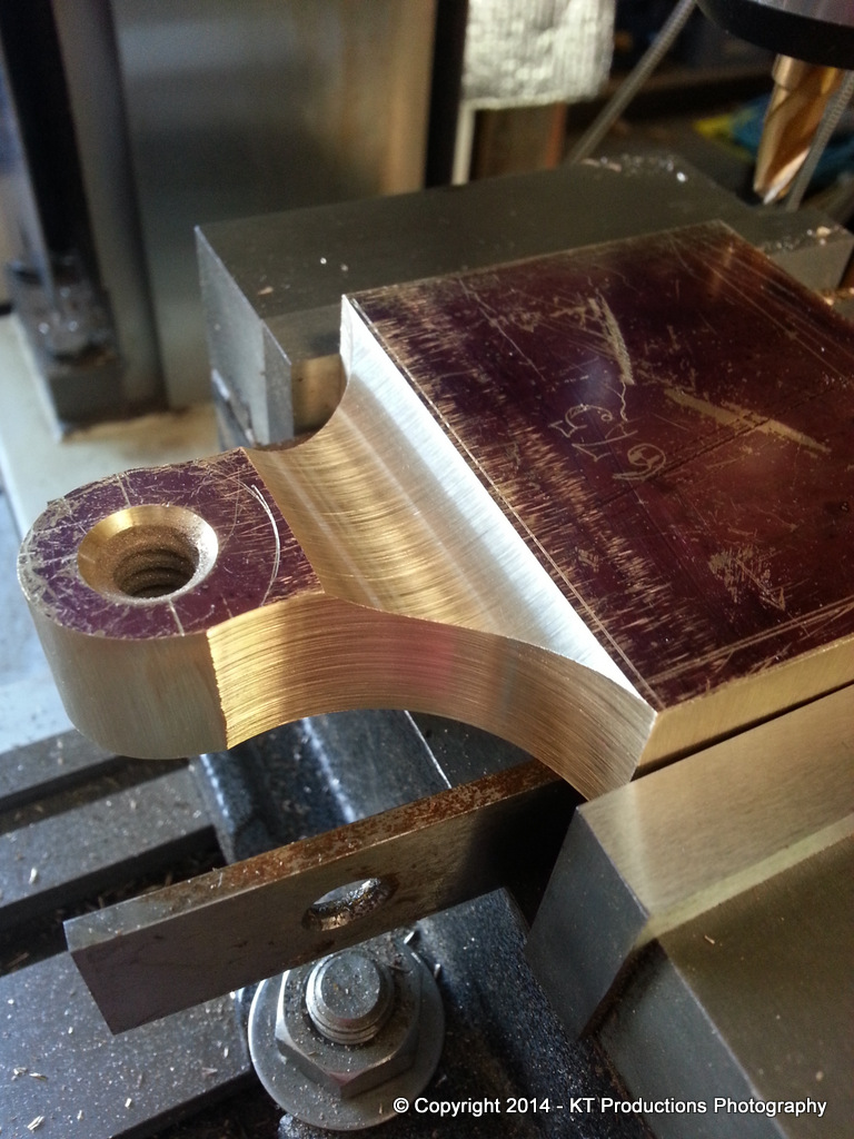
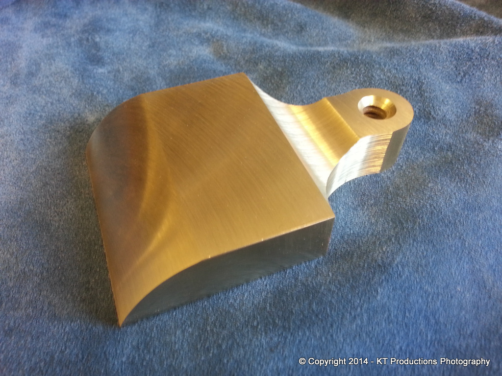
Ok...so now on to the lever cap block. First to slowly shave it down on the mill until it just fits....
I stuck the widest iron I currently have in the plane to test the geometry...note here that the bun is moved forward from its resting place as the bottom of the block is still there and obstructs the bun at the moment.,...
I then passed the assembly over to the QA department to check that the scribed shoulder depth was correct...
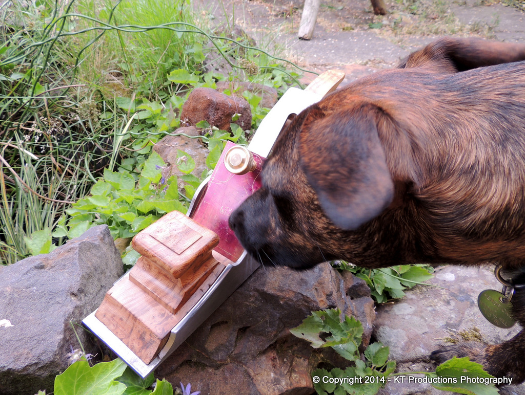
ALFIE confirmed that it was exactly as marked so the next stage of shaping the shoulders could go ahead! :mrgreen:
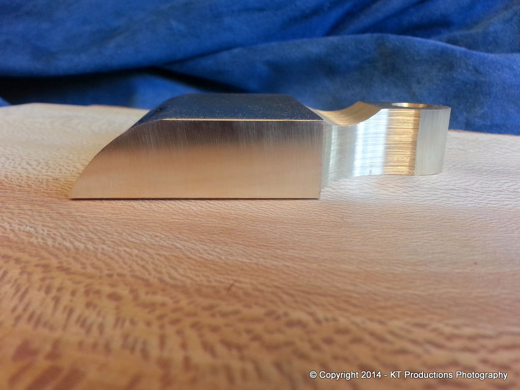
I was looking at Konrad Sauer's lever caps and fell in love with the huge chunky shapes...so it was with this in mind that I revised the thickness...keeping the entire block in place for now and shaping only the neck first.
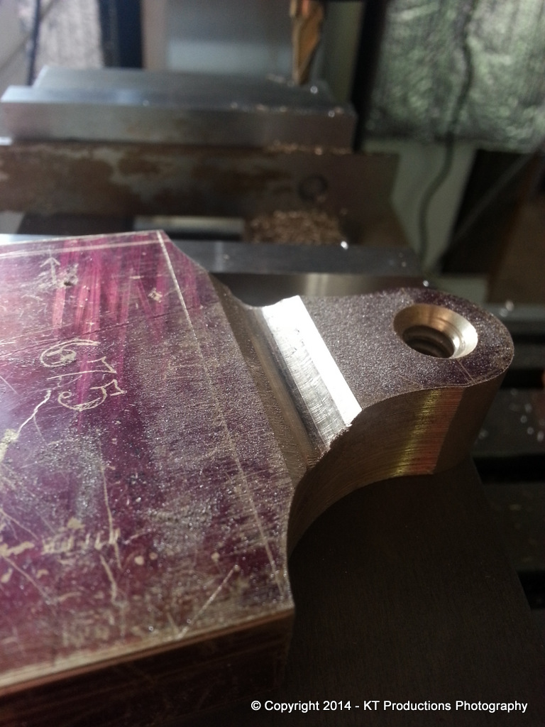
So..to the shoulder cutting.
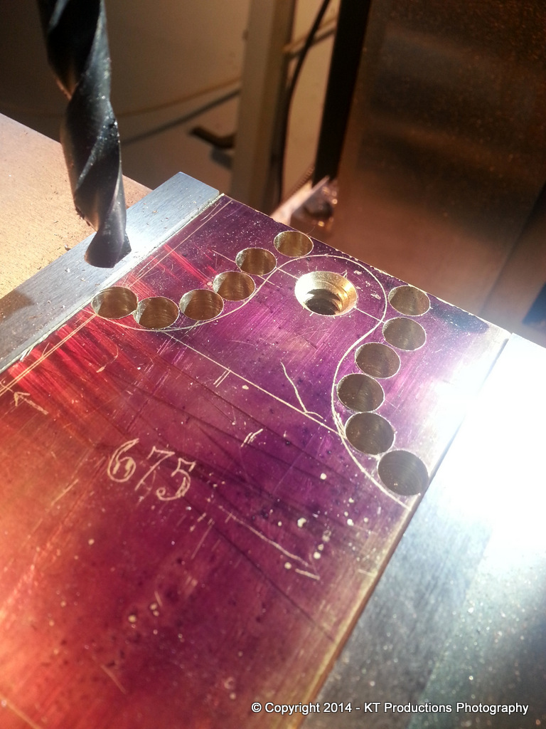
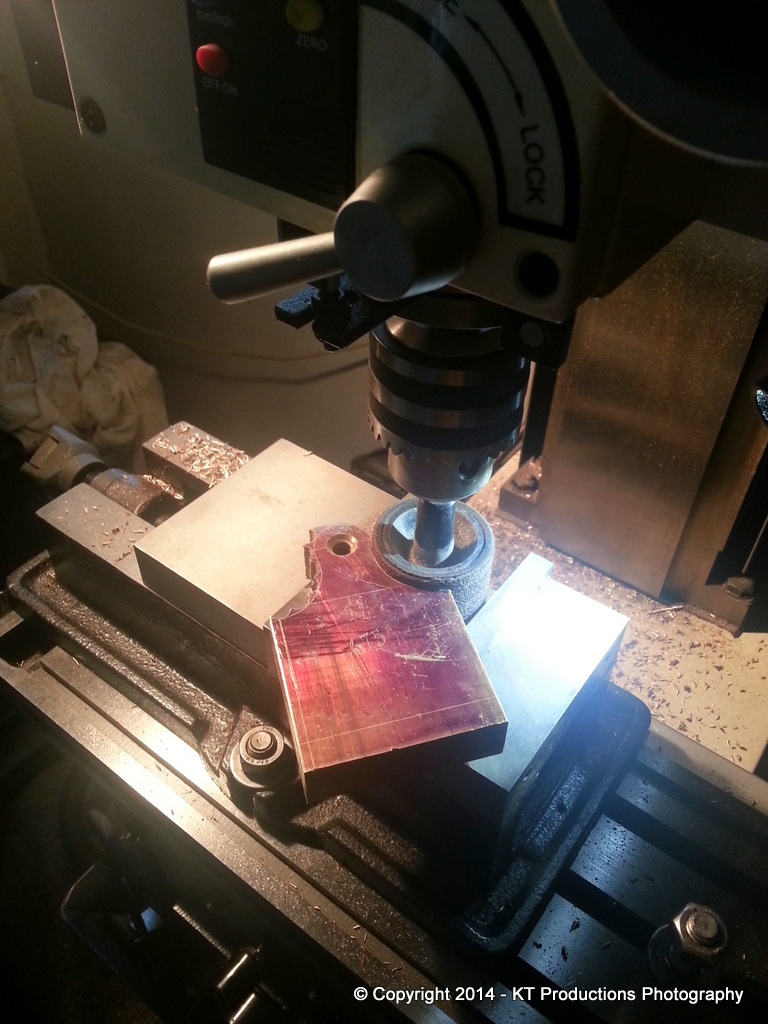
Richard once showed me the benefit of drilling thick stock in order to cut it and used a pillar drill to get vertical alignment. With the milling machine...a high level of accuracy was achievable and using the digital display I was also able to ensure symmetry for my sketched curves.
Another tip I learned from him was the use of a cold chisel to cut the bridges...
This is where we see that you should never throw away basketcase tools. A friend at work gave me this old Marples chisel with a view to putting a new edge on it. The entire tip had been snapped off!!! I just gave him another one and threw this one in the gash bin....until today! Grinding a double bevel on both sides of the stump I created a nice little cold chisel which was ideal for this job and made short work of the cutting:
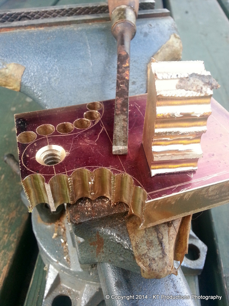
After a few minutes and a lot of noise the job was complete....
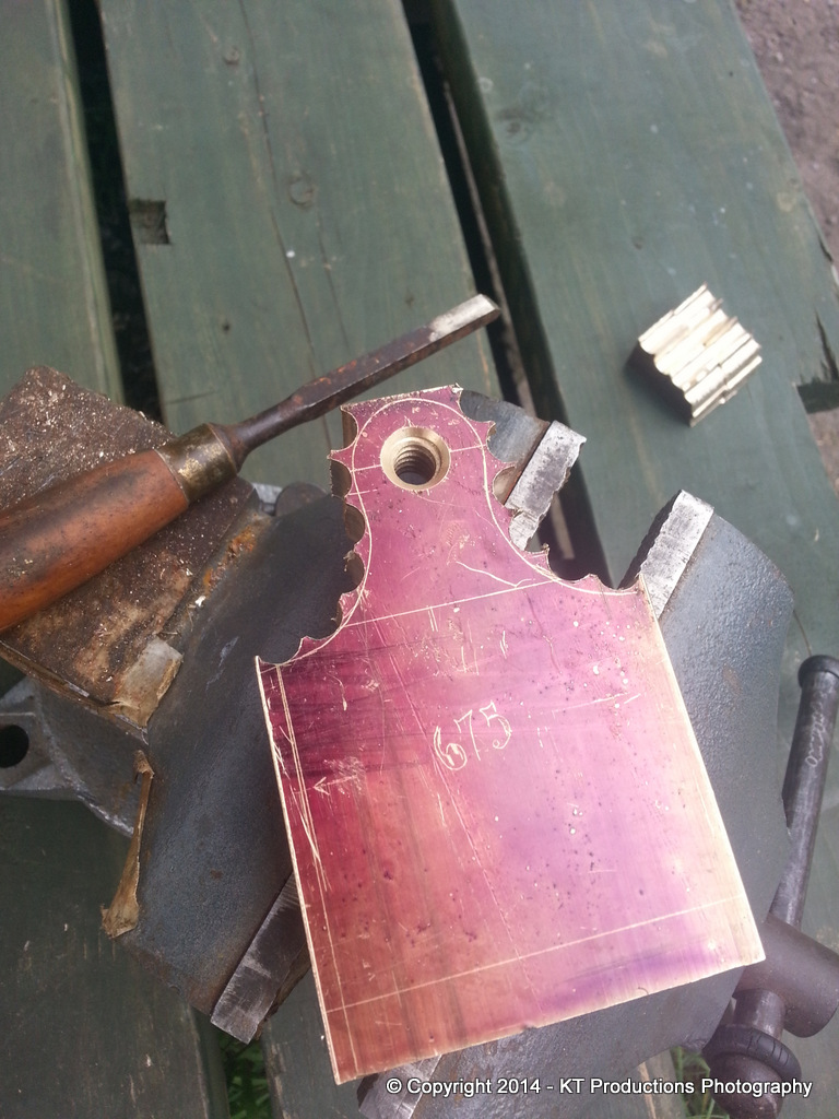
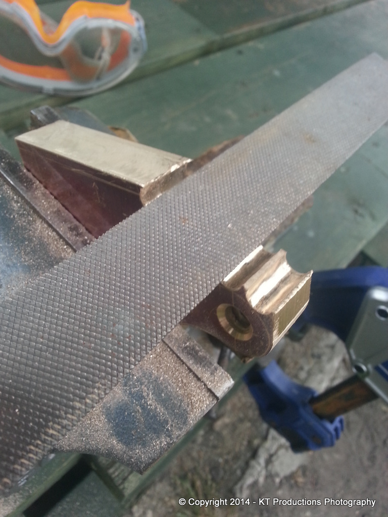
The very rough protuberances were quickly removed using a nice turnip Nicholson file....
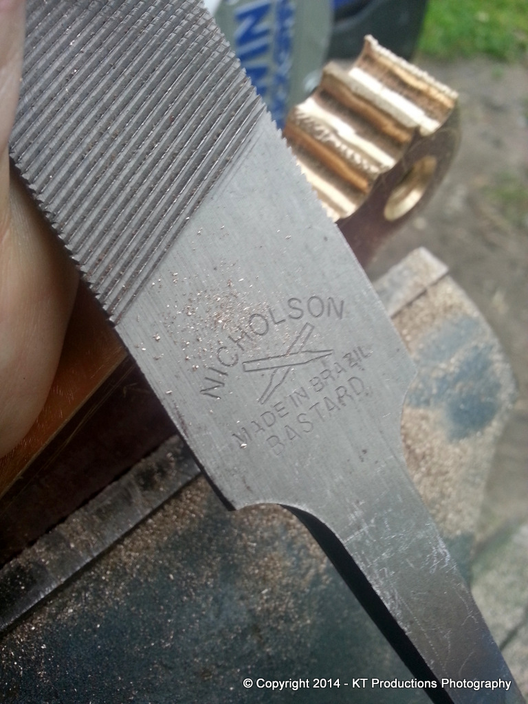
Files are the only tools I always buy new...or new old stock if possible. Again from bootfairs it's worth looking out for the good names as these are hugely expensive but a good file is worth it's weight in gold...
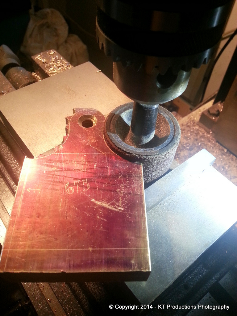
Once the worst points were filed down we were now in a position to create the final contour using an abrasive drum.
Axminster make a set of these and they have come in very handy more than once before.
You need a little luck sometimes and guess what...one of the drums was exactly the correct diameter to create the correct shoulder radius!!
I mounted this in a drill chuck in the milling machine because firstly the mill will go down to incredibly slow speeds allowing the job to be undertaken by hand safely. Secondly it allowed me to use the machine vise opened just the right amount to lower the drum between the jaws and allow the same jaws to act as a 90 degree platform to keep things plumb...
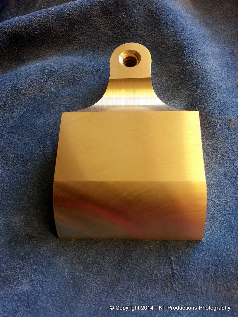
The top of the arm was formed using my little £10 linisher from the bootfair...
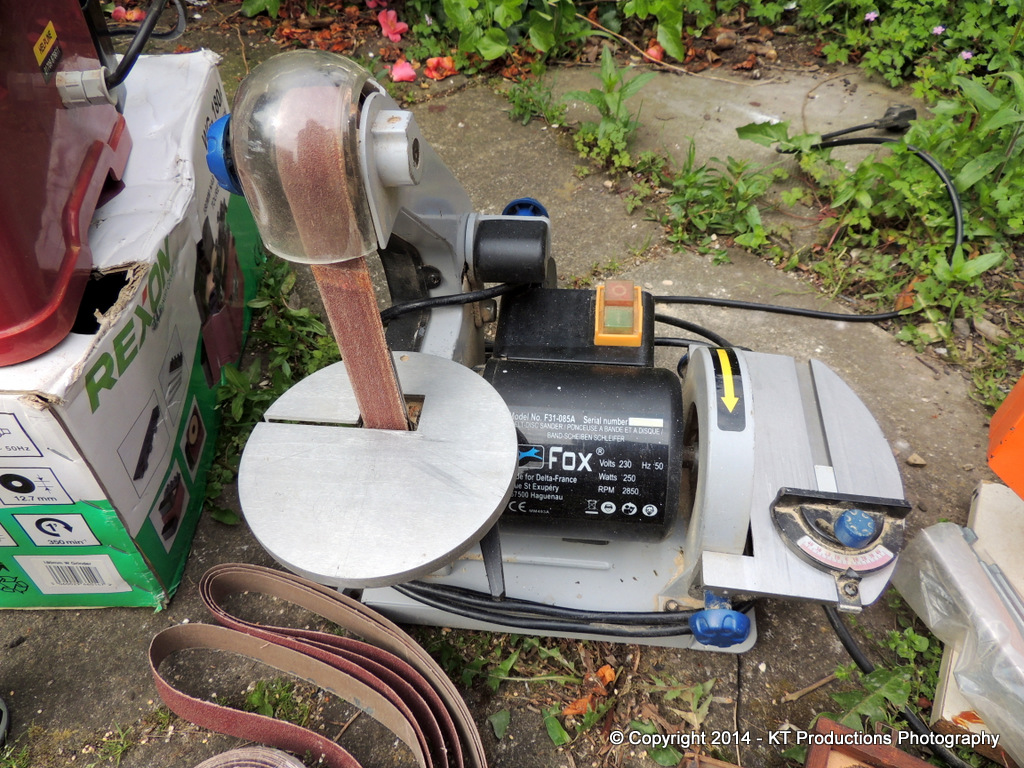
I knew that would be a grand investment! :wink:
So...what I thought would be a nightmare turned out, by using a combination of good tips and machines...a breeze!
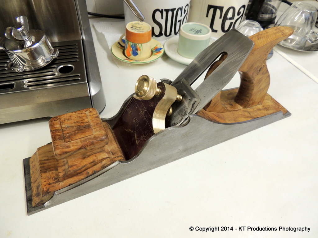
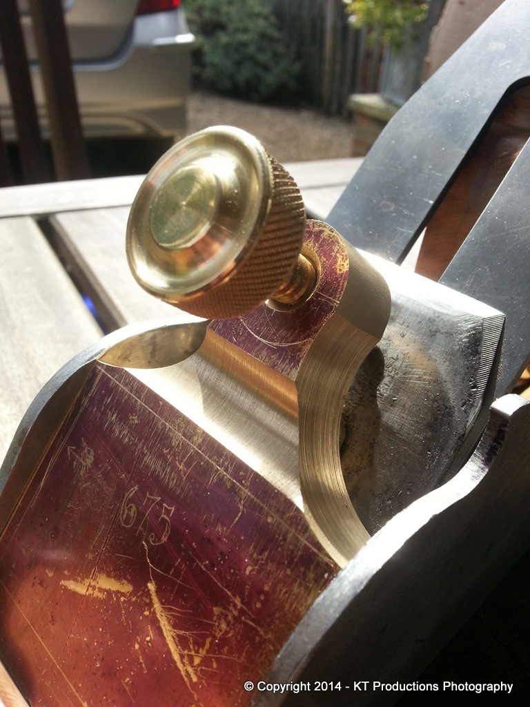
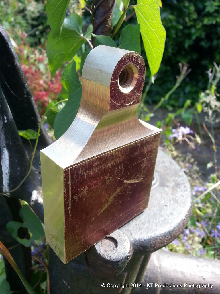
I think that the chunky knob which looked a bit out of scale yesterday now suits the chunkiness of the plane and cap perfectly...
I had been ready to make a slimmer one but I had a gut feeling I would regret doing so and this turned out to be correct.
Tomorrow I am working so on Thursday I shall be shaping the neck, cutting the toe of the cap and scalloping out the underside.
Until then...
Cheers
Jimi and ALFIE!
Ok...leaving my knob out of the equation for the moment
...an update on today's work.I have been discussing the iron setup with a number of people and getting some great advice but also this has given me a bit of a problem.
Whether we go for a single cut iron or a combination iron/cap iron setup is something I have been discussing offline...but either way I have now come to a decision point because if we choose the latter then we need a mortice in the bed. I was going to hold off but then I thought that it wouldn't hurt to just put a mortice in so that later on I can choose either at will. So..first thing to do today was to cut that mortice.
All was going well and then a setback!
As I was approaching the breakout...I thought to myself...shall I stop now and cut the remaining piece by hand...and I wish I had done now. Ordinary wood would have been ok but I keep forgetting we are dealing with burr here and guess what...
So...back to my restoration experience and out with the Titebond...and instead of having tomato soup with cheese and ham toastie being offered by Annie...I sat outside for half an hour and held the piece until it set up...
It'll be ok...this glue is better than the wood and it's hidden anyway but I was a bit annoyed for a brief moment!
Ok...so now on to the lever cap block. First to slowly shave it down on the mill until it just fits....
I stuck the widest iron I currently have in the plane to test the geometry...note here that the bun is moved forward from its resting place as the bottom of the block is still there and obstructs the bun at the moment.,...
I then passed the assembly over to the QA department to check that the scribed shoulder depth was correct...
ALFIE confirmed that it was exactly as marked so the next stage of shaping the shoulders could go ahead! :mrgreen:
I was looking at Konrad Sauer's lever caps and fell in love with the huge chunky shapes...so it was with this in mind that I revised the thickness...keeping the entire block in place for now and shaping only the neck first.
So..to the shoulder cutting.
Richard once showed me the benefit of drilling thick stock in order to cut it and used a pillar drill to get vertical alignment. With the milling machine...a high level of accuracy was achievable and using the digital display I was also able to ensure symmetry for my sketched curves.
Another tip I learned from him was the use of a cold chisel to cut the bridges...
This is where we see that you should never throw away basketcase tools. A friend at work gave me this old Marples chisel with a view to putting a new edge on it. The entire tip had been snapped off!!! I just gave him another one and threw this one in the gash bin....until today! Grinding a double bevel on both sides of the stump I created a nice little cold chisel which was ideal for this job and made short work of the cutting:
After a few minutes and a lot of noise the job was complete....
The very rough protuberances were quickly removed using a nice turnip Nicholson file....
Files are the only tools I always buy new...or new old stock if possible. Again from bootfairs it's worth looking out for the good names as these are hugely expensive but a good file is worth it's weight in gold...
Once the worst points were filed down we were now in a position to create the final contour using an abrasive drum.
Axminster make a set of these and they have come in very handy more than once before.
You need a little luck sometimes and guess what...one of the drums was exactly the correct diameter to create the correct shoulder radius!!
I mounted this in a drill chuck in the milling machine because firstly the mill will go down to incredibly slow speeds allowing the job to be undertaken by hand safely. Secondly it allowed me to use the machine vise opened just the right amount to lower the drum between the jaws and allow the same jaws to act as a 90 degree platform to keep things plumb...
The top of the arm was formed using my little £10 linisher from the bootfair...
I knew that would be a grand investment! :wink:
So...what I thought would be a nightmare turned out, by using a combination of good tips and machines...a breeze!
I think that the chunky knob which looked a bit out of scale yesterday now suits the chunkiness of the plane and cap perfectly...
I had been ready to make a slimmer one but I had a gut feeling I would regret doing so and this turned out to be correct.
Tomorrow I am working so on Thursday I shall be shaping the neck, cutting the toe of the cap and scalloping out the underside.
Until then...
Cheers
Jimi and ALFIE!
jimi43
Established Member
I should point out that there is little skill involved in pressing buttons and twiddling knobs!! I have to say that the lathe and milling machine make light work of onerous tasks but thanks for the words of encouragement as always! If I had 1/10th of the metalworking skills that dear Richard had then I would have attacked this with hammer and file but alas..that will never be...the "black stuff" still confounds me more often than not!
The tip with the cold chisel Andy was not that daunting really...I would be a charlatan to say otherwise! The mill made the bridges so close together they nearly joined up and it was a simple case of a quick "thwack" with a mallet and they parted company for good! I am thankful that Richard did point that tip out to me as I would have attacked it with a junior hacksaw and the result would have been close but a hell of a lot longer to achieve! :mrgreen:
What worries me the most is this lever cap is now entering my dreams! I went to sleep very late last night (actually when the birds were tweeting this morning! ) whilst pondering the next step...how to make the curves in the neck and the front and back.
Ideally, if I had a large enough round-nosed mill, I would have just milled it out but I didn't and the challenge therefore was to do as much on the machine as possible and then find a way of doing the rest.
A eureka moment hit me about 9am as ALFIE leapt on me wanting to go out for his "business walk"! Thanks ALF!
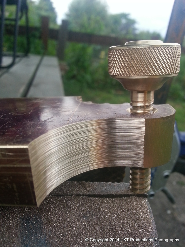
I used the biggest round-nosed mill I had to get a perpendicular cut accurately......
...and then used this as a guide to expand the curve using an abrasive covered brass rod in the lathe thus....
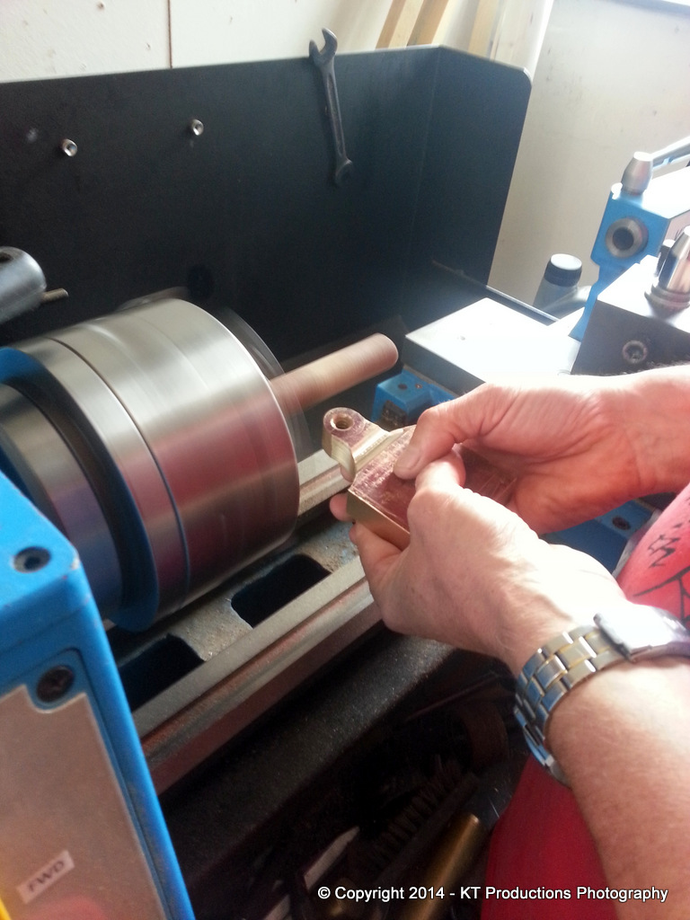
Now before the H&S boys come down on my like a ton of bricks...that chuck is not flying around as fast as would first appear! Annie (her indoors!) is a dab hand with the old Kodak and used a suitably slow shutter speed to give the illusion that I am completely and utterly bonkers.
Ok..it might not be quite an illusion but I am not that mad in this instance! :mrgreen:
At "relatively" slow speeds..the cutting power of this little setup was quite impressive...
....and so you can see where I'm trying to go with this.
Some will also note that the last photograph is taken in a foreign setting...that of Douglas' tablesaw! In order to finish this off I needed a 1" radius brass rod to turn into an impromptu drum sander and Douglas' was yet again "the man" who had such a piece! So I now have the right tool for the job...just need to keep all ten digits to finish it! :mrgreen:
Before I left for the afternoon, suitably satiated in the coffee department, he did insist I take an "action shot" complete with mystery shaving to play the role....
We did also have a chat about irons....and infill fastenings which were most helpful and put a few further ideas in my head to roll around randomly in the wee hours...until the next stage!
Cheers Douglas...most helpful!
More later...
Jimi
The tip with the cold chisel Andy was not that daunting really...I would be a charlatan to say otherwise! The mill made the bridges so close together they nearly joined up and it was a simple case of a quick "thwack" with a mallet and they parted company for good! I am thankful that Richard did point that tip out to me as I would have attacked it with a junior hacksaw and the result would have been close but a hell of a lot longer to achieve! :mrgreen:
What worries me the most is this lever cap is now entering my dreams! I went to sleep very late last night (actually when the birds were tweeting this morning!
) whilst pondering the next step...how to make the curves in the neck and the front and back.Ideally, if I had a large enough round-nosed mill, I would have just milled it out but I didn't and the challenge therefore was to do as much on the machine as possible and then find a way of doing the rest.
A eureka moment hit me about 9am as ALFIE leapt on me wanting to go out for his "business walk"! Thanks ALF!
I used the biggest round-nosed mill I had to get a perpendicular cut accurately......
...and then used this as a guide to expand the curve using an abrasive covered brass rod in the lathe thus....
Now before the H&S boys come down on my like a ton of bricks...that chuck is not flying around as fast as would first appear! Annie (her indoors!) is a dab hand with the old Kodak and used a suitably slow shutter speed to give the illusion that I am completely and utterly bonkers.
Ok..it might not be quite an illusion but I am not that mad in this instance! :mrgreen:
At "relatively" slow speeds..the cutting power of this little setup was quite impressive...
....and so you can see where I'm trying to go with this.
Some will also note that the last photograph is taken in a foreign setting...that of Douglas' tablesaw! In order to finish this off I needed a 1" radius brass rod to turn into an impromptu drum sander and Douglas' was yet again "the man" who had such a piece! So I now have the right tool for the job...just need to keep all ten digits to finish it! :mrgreen:
Before I left for the afternoon, suitably satiated in the coffee department, he did insist I take an "action shot" complete with mystery shaving to play the role....
We did also have a chat about irons....and infill fastenings which were most helpful and put a few further ideas in my head to roll around randomly in the wee hours...until the next stage!
Cheers Douglas...most helpful!
More later...
Jimi
bugbear
Established Member
jimi43":1118d7jv said:...and then used this as a guide to expand the curve using an abrasive covered brass rod in the lathe thus....
Now before the H&S boys come down on my like a ton of bricks...that chuck is not flying around as fast as would first appear! Annie (her indoors!) is a dab hand with the old Kodak and used a suitably slow shutter speed to give the illusion that I am completely and utterly bonkers.
If you were worried, you could always have rigged the lever cap to the top slide, and followed "milling in the lathe" procedures and techniques.
There's always another way...
BugBear
xy mosian
Established Member
jimi43":3g19hu4i said:ALFIE then acted as a black background to get a profile shot in contrast....
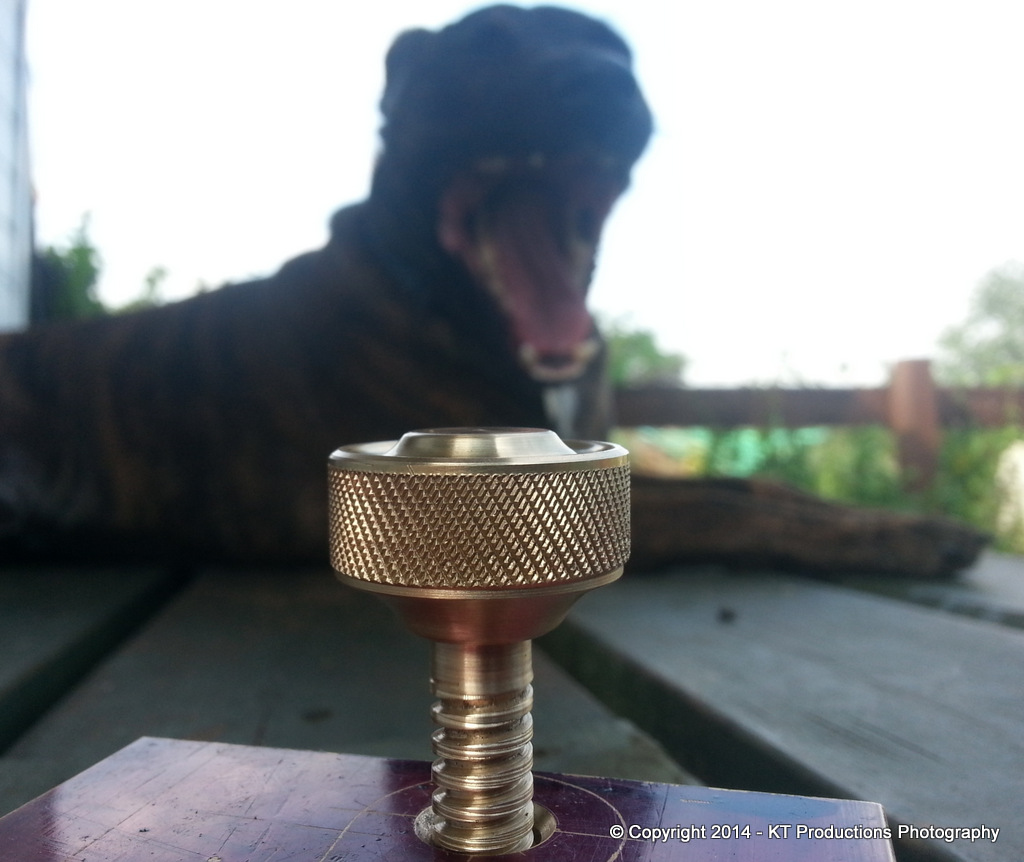
...although he did insist on showing you all his Jurassic Park "T-REX" impression....(suitably blurred so as not to frighten the kids!) :mrgreen:
Here's me thinking you had found a pet Womble
Fascinating reading and a very instructive thread.
Thank you.
xy
Following on from the suggestion about it being safer to hold the workpiece on the cross-slide, two more suggestions.
1. Would hardwood dowel (of different diameters) be rigid enough to substitute for the piece of brass? OK, it takes away your excuse for a trip for coffee-satiation, but could mean you could produce the entire curve with a variety of diameter drums? If rigidity is a problem, mount the dowel between centres? Or....
2. Don't know whether it would produce a decent finish, but you could mount a fly cutter on a mild steel bar between centres and then shim the brass up to the appropriate level so you could fly cut the whole surface using the cross slide and leadscrew?
jimi43
Established Member
Hi Dick
Thanks for the advice...however...now the scallop is all but there it guides the larger one very easily and by eye I inched up to the marked lines..
I'm sure your suggestions will be adopted should I ever find myself in need to do this again...but it will be quite a while hence I can tell you! :mrgreen:
So that was that bit over...and the sun was shining so I was in a bright mood...
This afternoon I had root canal treatment at the dentist with my wife as the assistant so the thought of milling huge lumps of brass put me right off the next bit but I removed most of the front with a large mill and then I used a dreadnought file to get the profile and this monster to do the rest...
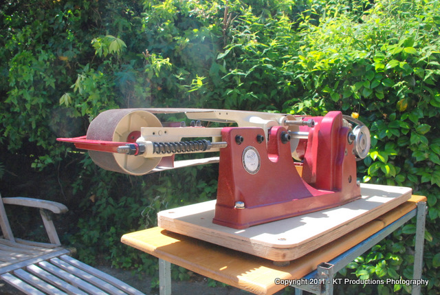
Some of you may remember the restoration thread I did back in 2011...I don't use it much but when I do...it eats things!
Then I did the final finishing on my other homemade jobbie...
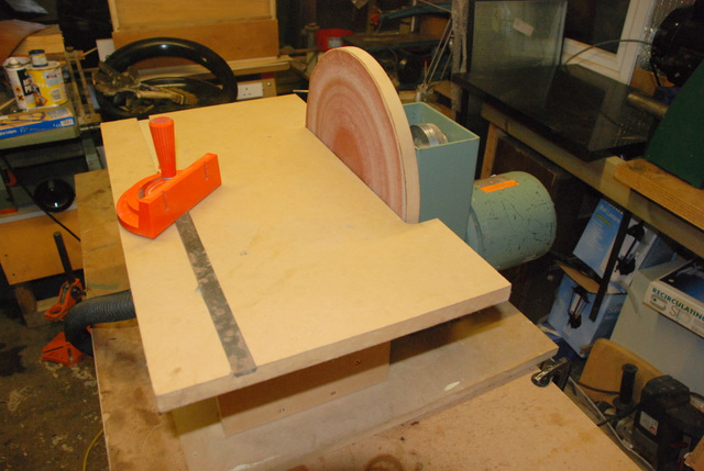
...wiith a fine disc and it has a nice Corian bed now so registration is a breeze! As long as you remember not to go beyond the centre!! This thing has more torque than Jeremy Paxman! :mrgreen:
So that's the neck...the front and the sides sorted....
I'm not particularly interested at refining the finish at this stage as I may need to move the toe back slightly depending on where the tip rests once I have set the location of the pivot point up....so I need to get the irons done first. After that I shall scallop the underside using the same French curve shape to match the top curve...I'm not looking forward to that bit!
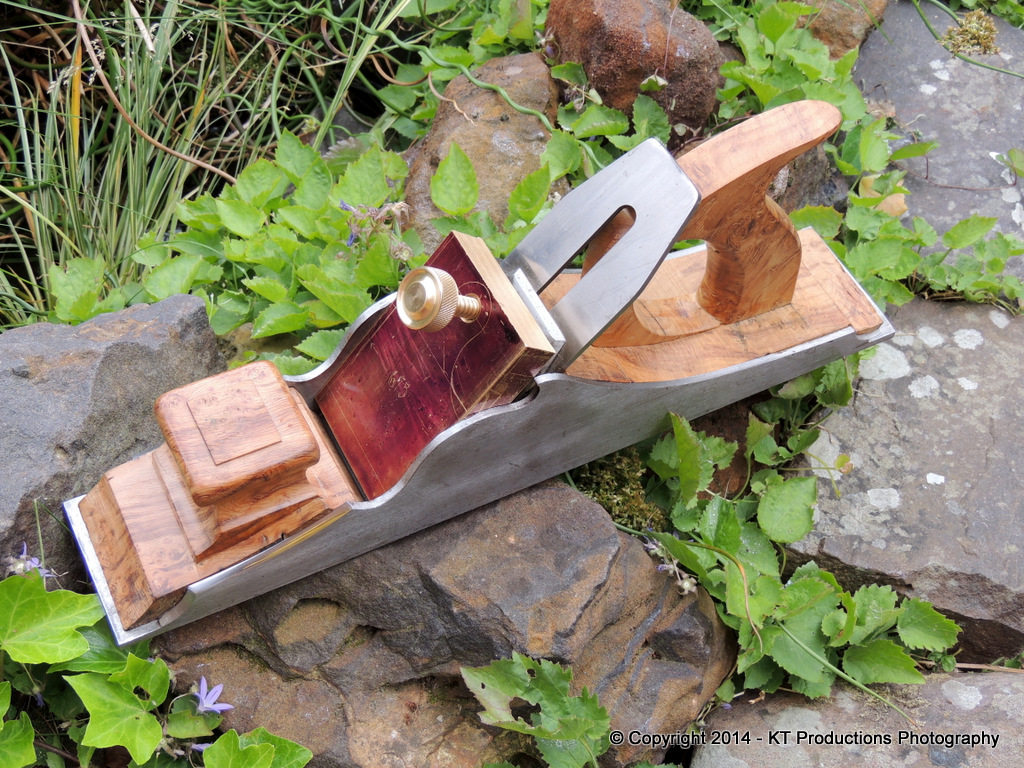
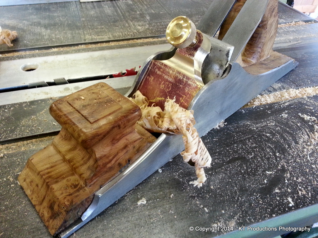
But for now I'm fairly happy with progress...
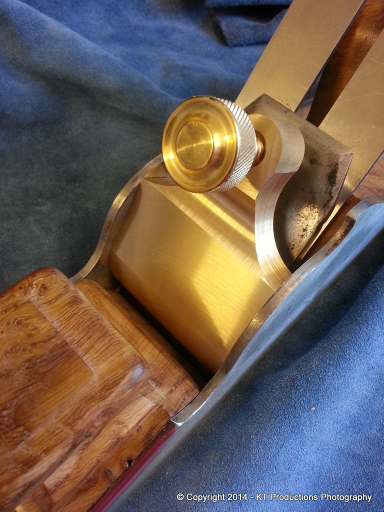
It's starting to look like a proper plane now...
I may have to reinforce the wall behind the bench though...the inertia once this monster gets going is a bit worrying!! :mrgreen:
Jim
Thanks for the advice...however...now the scallop is all but there it guides the larger one very easily and by eye I inched up to the marked lines..
I'm sure your suggestions will be adopted should I ever find myself in need to do this again...but it will be quite a while hence I can tell you! :mrgreen:
So that was that bit over...and the sun was shining so I was in a bright mood...
This afternoon I had root canal treatment at the dentist with my wife as the assistant so the thought of milling huge lumps of brass put me right off the next bit but I removed most of the front with a large mill and then I used a dreadnought file to get the profile and this monster to do the rest...
Some of you may remember the restoration thread I did back in 2011...I don't use it much but when I do...it eats things!
Then I did the final finishing on my other homemade jobbie...
...wiith a fine disc and it has a nice Corian bed now so registration is a breeze! As long as you remember not to go beyond the centre!! This thing has more torque than Jeremy Paxman! :mrgreen:
So that's the neck...the front and the sides sorted....
I'm not particularly interested at refining the finish at this stage as I may need to move the toe back slightly depending on where the tip rests once I have set the location of the pivot point up....so I need to get the irons done first. After that I shall scallop the underside using the same French curve shape to match the top curve...I'm not looking forward to that bit!
But for now I'm fairly happy with progress...
It's starting to look like a proper plane now...
I may have to reinforce the wall behind the bench though...the inertia once this monster gets going is a bit worrying!! :mrgreen:
Jim
jimi43
Established Member
Racers":1rht6o0s said:More excellent work Jimi.
You will be needing that blade sorting soon.
Pete
Thanks again Pete...appreciated. It's chunky rather than antique thin for a number of reasons but the top of the list is because it matches the chunkiness of the plane body itself.
I'm glad you brought up the subject of irons...I have now decided there will be three made next week...all from 01 tool steel.
As we discussed at Richard Arnold's, I want to send you one to harden in the traditional way so you better get some burgers in! :mrgreen:
Another UKW member has also kindly offered to help me with one using more modern methods and he also has a surface grinder to ensure the face is perfectly flat....so that's another UKW member offering their services and kindness at this stage for which I am eternally grateful.
I want to see how the methods compare...something that has always interested me but judging by the way your scraper plane performs...I am sure we will have a a set of irons to go with this plane for a long time to come. Perhaps I shall grind different bevels on them for a bit of variety too!
What do you think?
Jimi
tobytools
Established Member
Superb work so far Jimi, I can only echo what has already been said.
This wip is with out a dout the one I most look forwards to see, it's such a great project. Knowing the story that is behind it just takes me away.
You should honestly be proud mate, and I'm sure there is a forge master looking down and smiling.
I too, can't wait for the irons to hurry up and get here
The diffrent bevels is a great idea, like the QS LA block there is sevral irons for diffrent jobs and it just makes the tool that much better.
With the combined efforts of other ukw member mucking in this will truley be the wip of a life time.
Thank you for sharing this journey,
I for one really appreciate it.
Thanks mate
TT
jimi43
Established Member
Hi Toby
Thanks for your kind words mate...and yes...I am taking far more care over this one than any of my previous projects simply because this plane means so very much to me. Bevels...ah..not going to the same extremes as a BU plane because this one is the traditional BD but what I will be doing is looking at the whole combination of the cutting unit (be it one or two elements) and on the cap iron...I need to look at lever cap flex (although frankly I think this will be minimal with the thickness of irons being tested, and in particular...where that pressure point sits at the leading edge of the lever cap.
I am researching this today partly out of total ignorance of the geometry but mostly because I don't want to go shaving down the lever cap willy nilly and then find that I should have left it longer because the geometry dictates a certain length.
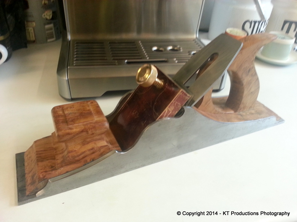
My initial empirical findings based on the selection of lever capped planes I have is shown below....
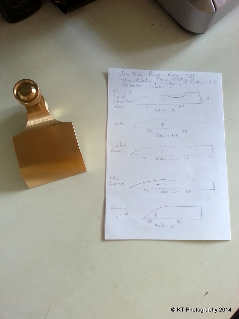
As can be seen from the profiles of the various lever caps I have....the ratio of the lengths from the pivot point to the back versus the pivot point to the front varies anywhere between 1.2:1 to 3.6:1 and all of these work fine.
Also the distance from the mouth to the front of the lever cap..the first pressure point....varies hugely.
That being said...I think that this is because the maths behind all of this was not really analysed way back then and different builders adopted a design and stuck to it. I do think that it's possible there is an optimum and the issues are:
1) Allowing an even but firm pressure on the iron/cap iron assembly but not so tight that tap adjustment can't be performed easily
2) Preventing the leading edge of the lever cap from interfering with the exit of the shavings
3) Ensuring the optimum flatness of iron to bed contact
4) Pure aesthetics.
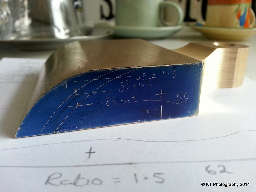
I originally adopted a basic design from a dimensional point of view from the Scottish panel plane I have, simply because the size of the plane most closely matched that of this one.
That fixed the pivot point and distance from that point to the rear of the lever cap.
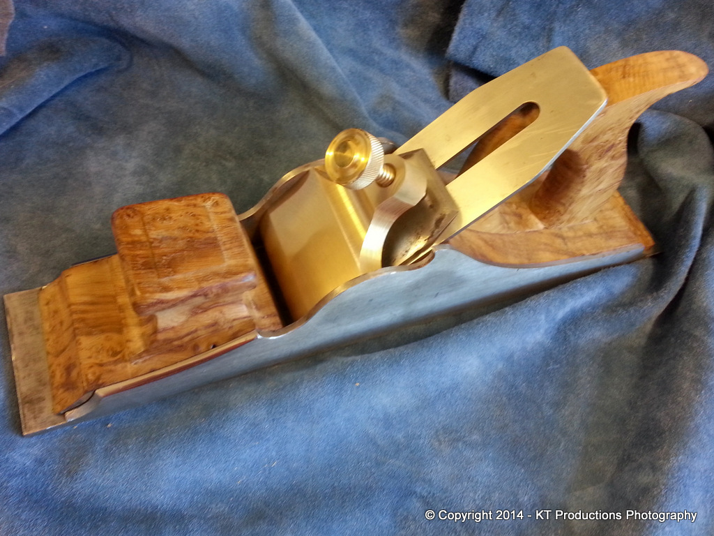
Now I have the front to play with once I have done enough research to be happy and this will allow me to trim the leading edge thus:
My gut feeling is telling me that a front/back ratio of 1.5 is right...it just looks right. There is enough clearance in the front to be clear of the mouth by a lot....the front pressure point is still on the steel "frog" and it looks cool!
....oh...and as you can see from the background of that picture...it is exactly the same as the Scottish panel!! 8)
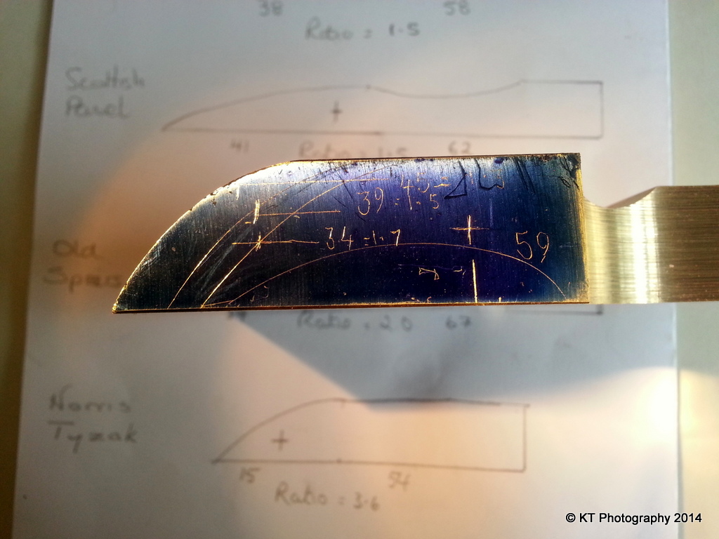
I shall be trawling the Internet tonight...and...I will be seeking advice from one of my favourite plane building guys...
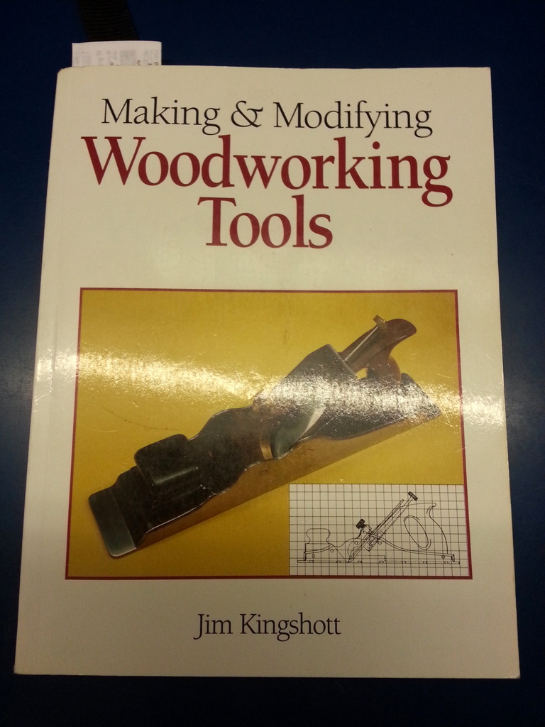
....who just happens to have a whole chapter on the subject!
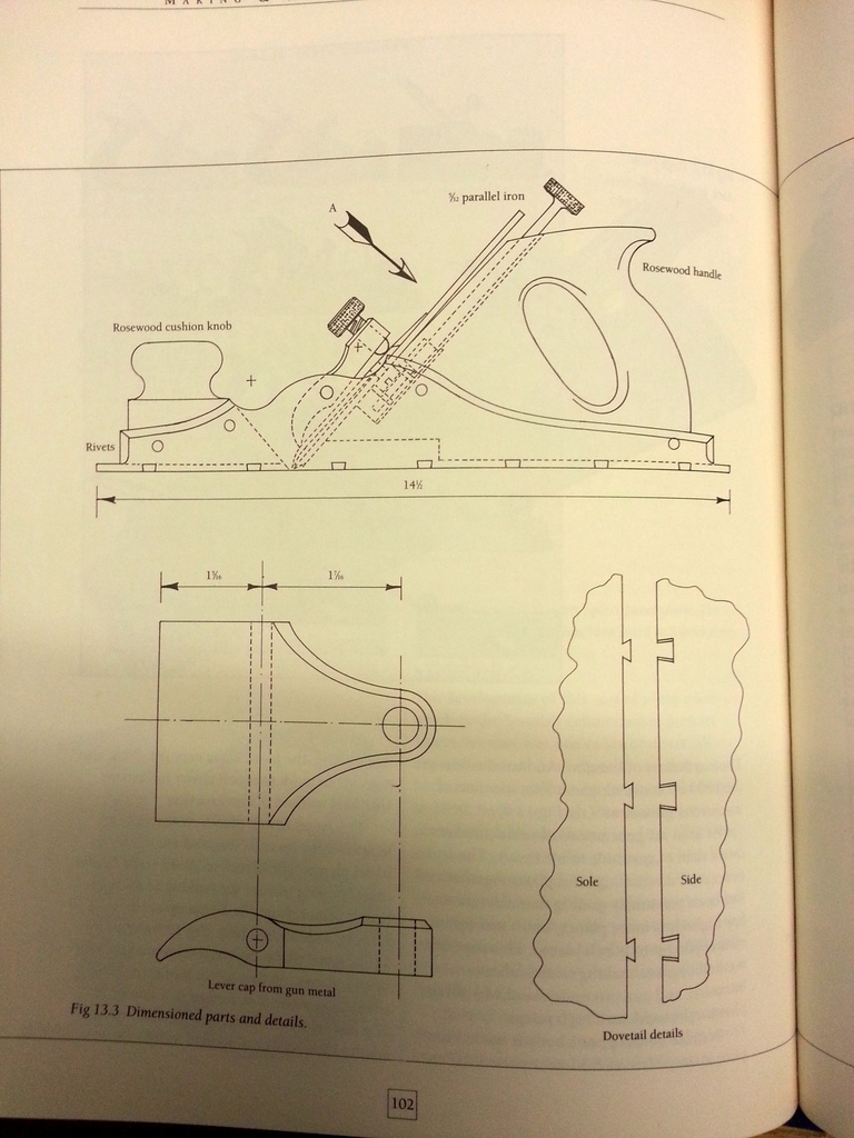
.....although just a quick glance at this last picture makes me think his ratio is not 1.5.
At the end of all of this, it might prove not to matter one iota but I don't want to be making another lever cap anytime soon that's for sure! :shock:
Pete...yes mate...empty the water...get the frogs out...fire up the burgers and get ready to rock!
I need to get some more steel from my supplier as I thought I had more wide stock but alas...it's all 60 mm which is just too narrow...should be here quickly though.
More tomorrow as I tinker further...
Jimi
Thanks for your kind words mate...and yes...I am taking far more care over this one than any of my previous projects simply because this plane means so very much to me. Bevels...ah..not going to the same extremes as a BU plane because this one is the traditional BD but what I will be doing is looking at the whole combination of the cutting unit (be it one or two elements) and on the cap iron...I need to look at lever cap flex (although frankly I think this will be minimal with the thickness of irons being tested, and in particular...where that pressure point sits at the leading edge of the lever cap.
I am researching this today partly out of total ignorance of the geometry but mostly because I don't want to go shaving down the lever cap willy nilly and then find that I should have left it longer because the geometry dictates a certain length.
My initial empirical findings based on the selection of lever capped planes I have is shown below....
As can be seen from the profiles of the various lever caps I have....the ratio of the lengths from the pivot point to the back versus the pivot point to the front varies anywhere between 1.2:1 to 3.6:1 and all of these work fine.
Also the distance from the mouth to the front of the lever cap..the first pressure point....varies hugely.
That being said...I think that this is because the maths behind all of this was not really analysed way back then and different builders adopted a design and stuck to it. I do think that it's possible there is an optimum and the issues are:
1) Allowing an even but firm pressure on the iron/cap iron assembly but not so tight that tap adjustment can't be performed easily
2) Preventing the leading edge of the lever cap from interfering with the exit of the shavings
3) Ensuring the optimum flatness of iron to bed contact
4) Pure aesthetics.
I originally adopted a basic design from a dimensional point of view from the Scottish panel plane I have, simply because the size of the plane most closely matched that of this one.
That fixed the pivot point and distance from that point to the rear of the lever cap.
Now I have the front to play with once I have done enough research to be happy and this will allow me to trim the leading edge thus:
My gut feeling is telling me that a front/back ratio of 1.5 is right...it just looks right. There is enough clearance in the front to be clear of the mouth by a lot....the front pressure point is still on the steel "frog" and it looks cool!
....oh...and as you can see from the background of that picture...it is exactly the same as the Scottish panel!! 8)
I shall be trawling the Internet tonight...and...I will be seeking advice from one of my favourite plane building guys...
....who just happens to have a whole chapter on the subject!
.....although just a quick glance at this last picture makes me think his ratio is not 1.5.
At the end of all of this, it might prove not to matter one iota but I don't want to be making another lever cap anytime soon that's for sure! :shock:
Pete...yes mate...empty the water...get the frogs out...fire up the burgers and get ready to rock!
I need to get some more steel from my supplier as I thought I had more wide stock but alas...it's all 60 mm which is just too narrow...should be here quickly though.
More tomorrow as I tinker further...
Jimi
xy mosian
Established Member
In the page shot of Kingshott's book I wonder if the pivot point is more related to the plane body than the lever? Personally I would consider leaving the final decision until I had an iron, and possibly cap iron, to play with.
I am sure you will get it right.
xy
I am sure you will get it right.
xy
jimi43
Established Member
xy mosian":1j9g51n8 said:In the page shot of Kingshott's book I wonder if the pivot point is more related to the plane body than the lever? Personally I would consider leaving the final decision until I had an iron, and possibly cap iron, to play with.
I am sure you will get it right.
xy
Yes xy....that is what I think...the dimensions don't add up. Generally speaking I'm pretty sure that this will be 1.5:1 because it is the ratio of the vast majority of planes I have (give or take) and also if that were the one I chose...the leading edge comes just behind where the cap iron comes off its initial bevel and right in the centre of the frog...with enough room of shavings to curl out.
I will indeed wait until I have made the new irons and cap iron and then working on this theory...dry fit the lever cap and see how it sits.
Jimi
Similar threads
- Replies
- 12
- Views
- 595
- Replies
- 8
- Views
- 986
- Replies
- 8
- Views
- 1K