wadkin PK restoration

UKworkshop.co.uk

Help Support UKworkshop.co.uk:

This site may earn a commission from merchant affiliate links, including eBay, Amazon, and others.
I haven't seen any pics or cuts of the PK brake. Is it anything more than a resistor bank that sinks the motor's energy after power has been removed...?

Now as far as jewerly is concerned... I thought I was going to receive an official Wadkin decoder ring in the mail once I bought the PK....? Guess I should stop holding my breath... :(
 
wallace":15xzzv57 said:
have you got any photos of your collection of iron. Some people may think you have obsessive compulsive disorder

Oh.. I definitely have an obsession with table saws.

Here's a photo of my favorite machine;

The Whitney No. 177 Variety Saw with rolling table:

13508-A.jpg


I have a number of those brakes lying around. As it turns out, they don't function very well at the higher voltage/frequency. I'm amazed by how much smaller they are than the dynamic brakes we typically find in North America.

-Arthur
 
Arthur
I love the way they did the crank handle to spred the tables. Its no left tilt is it ?thats just the tilt handle on the wronge side to pull for right tilt is it not. Show them your wadkin pattern mills Aruthur or the RU.

j you have have 3 wadkins to get the ring right Mark.

jack
English machines
 
tool613":19yren6r said:
Its no left tilt is it ?thats just the tilt handle on the wronge side to pull for right tilt is it not. Show them your wadkin pattern mills Aruthur or the RU.

Jack, It's a right tilt. This is one of the best tilt mechanisms I've seen. That handwheel will free spin a couple of revolutions in either direction. I'm trying really hard not to completely hi-jack the thread. That said, I'll post more photos if folks want to see them.

-Arthur
 
Hi all I did some tweaking of the fence to make it at right angles to the table and then parallel to the blade. I also set the blade angle indicator too.

x1.jpg


Heres a pic of the brake and start/stop, I have put it where the original switch was bolted it looks pants.
x10.jpg


Jack is there a procedure for makeing the sliding table the same level as the main table

x2.jpg


Heres some pics of the completed saw


x4.jpg


x3.jpg


x9.jpg


h
x8.jpg


x11.jpg


x12.jpg


x5.jpg


x6.jpg


It makes my Sagar rip saw look pretty small

x7.jpg


Lastly a clip of it in action, the blade is the one that came with it and is pretty goosed.

http://www.youtube.com/watch?v=FvaJruIM0k0&feature=plcp

Arthur, please feel free to hijack away
 
The PK looks awesome wallace... congrats. :)

That brake does a fantasic job off stopping that blade... =D>

You wouldn't by chance have a nice close up shot of the slider release pin handle would you...? I'm making one from scratch, and I'm having a hard time finding a good reference pic to work from.

wallace":2r1zz8kr said:

Congrats again...

Jarrett
 
Hi Jarret, I have the brake set on its slowest setting because I did not know how my static converter would react.
Heres a pic of the handle, if you want something closer I will get it.

c11.jpg


Mark
 
That was the slowest setting...? Wow, it must stop on a dime when it's cranked to the max....

That pic is perfect... thanks

A question if you don't mind.... Are PK accessories difficult to source in the UK...? It's near impossible to find anything on this side of the pond.

Jarrett
 
Jarret, I get the impression that PK accessories are like rocky horse poo. I have seen one set of quadrant and protractor sell on ebay recently and they went for over £200. I am keeping my eyes open because I'm missing the protractor and half of the quadrant. Have you seen Arthurs page, http://www.owwm.net/
Mark
 
I've read all of Arthur's blog several times now. I even wrote to him today via an email address I found on his site. Hopefully my message doesn't get caught up in his spam filter.

I believe my biggest problem isn't going to be the more standard accessories though. Now that I have enough posts I can show a pic that will explain better than I can.

IMAG1238edit.jpg


As you can see from the pic above. Not only am I missing the usual fence out rigger, but I'm also missing the extra bit of table casting usually in place to mount the crown guard support. That particular piece never existed on my PK. I don't have a photo of it, but the machining along that edge of the table is continuous, so it doesn't appear to be a modification by a previous owner.

My PK was meant to have a full size extension wing off that side. The only other real world example of this model that I've been able to find is the first PK Arthur bought from the UK. I don't think this is his saw exactly, but it's the example he has posted on his website.

4.jpg


I'd settle for the fence out rigger for the short term, but I'd much rather have the full extension if I could ever find one... I was hoping my new found friends in the UK might be able to help me :D
 
The PK accessories are nearly impossible to find. That's why I went down the road of making the reproduction quadrant. Jack recently asked me about the protracter and I've been considering that as a project for the near future. I made the master pattern for the split quadrant a little heavy from a block of cedar. I then had the foundry cast a set in aluminum. These are what I'm using for the master for all new castings. Getting rough castings made is no problem. I just need to drop the patterns at the foundry and wait six to eight weeks for the castings to be ready. The machining isn't all that difficult. The spring loaded locator pin on the left side will take some tome to reproduce, but the components are readily available from McMaster. If you already have the left side of the quadrant, then making the right side is pretty easy. You would need to reference the existing gauge since it might have variations over other generations/production runs (like the one I'm using for reference). The right side only has to match the pin holes height anf face location of the existing left side. I hope this makes sense. I' can picture the gauge in my head, something you might not be able to do if you haven't held one in your hand.

Here's a picture of my reproduction gauge:
PK-q-1.jpg


You can see it's a little heavier than the original. I added weight where I commonly see them broken.

I hope this helps.

-Arthur
 
That looks spot on Arthur, May I ask what is the purpose of haveing two adjustable fences? Mine has a crack and is very pitted.

2.jpg


There's one problem with the uk and that is that their is very little industry left. I doubt very much if their are any places that do castings anymore and if their is I bet its a kings ransome.
Mark
 
I can't speak for Wadkin from the early 50's but I had it in my head that the second half was meant to allow easy, and repeditive set ups to cut tapers. The first half, like what you have Mark, locks at 90 degrees to the blade, and then you set your taper angle relative to it.

That's an assumption on my part, but it seems to work.

Jarrett
 
Mark,

I think you might be surprised. I live on the south coast (not noted for its heavy industry) and there are a number of foundries in this area.

Jim
 
Mark,

It's not true that there's no industry left in the UK. There's a lot of industry about, but it's changed a lot in the last generation. Yetloh is quite right when he says there are foundries about, but many of them are geared for production runs, and some may not be keen on doing jobbing work, but you can find them. One of the reasons that this is so is because one-off castings are very rare in engineering these days (nobody will bear the costs of patternmaking for just one component), anything of the size of a mitre guide would be fabricated in mild steel - and herein may lie an answer to your problem. There are plenty of small fabrication shops about. You may even be able to make something up yourself, if you have a welding set. Design it carefully so that you do as much preliminary machining (cutting curved slots, etc.) before welding, then the final machining will be just skimming things true. If you can find a fab. shop that can anneal the fabrications for you after welding, even better - this will avoid any distortion on machining as thermal stresses set up on welding are released.

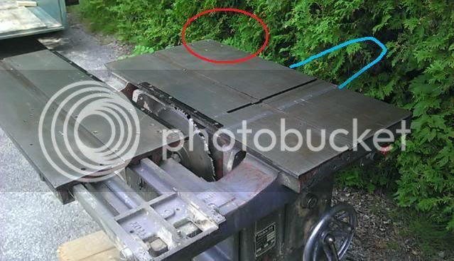
On the table alignment problem, you may be able to make and fit shims between the table and base castings to bring everything level. Make the shims so that they fit as close to the fixing bolts as possible, and of equal thickness all round each bolt to avoid any distortions to the table on applying bolt loads. Try temporarily wedging the tables true with the bolts released, then check each shim gap with feeler gauges to find how much each needs. You can buy shimstock from any good engineer's merchant - or on the web.
 
wallace":1aw3p0kj said:
May I ask what is the purpose of haveing two adjustable fences?
there are probably 100 things i have not yet learned it can do but here are some.

the quadrant will lock in to presets.
IMG_0542.jpg


it can be set to complimentary angles or mirror angles with one setting.
IMG_0544.jpg


it can be locked near the front of the table for increased cross cut with 90 pin lock.


it can be used as a tenon jig with tapering of stock
IMG_0546.jpg

IMG_0547.jpg


not sure if all slider tables do this but the PK slides open for tapers of to 5".
IMG_0548.jpg


Near the base of the table are the last few letters (TRE) it is off the main grid scribe. This etch set the double back miter front and back fence to 90. If you place the front fence in the miter(45 dregs) pre set and the back fence to the mark in the pic below the fences are set to 90 to each other and then can move in unison.
backfence90.jpg


jack
English machines
 
Here are few pictures of an unknown quadrant that came up on e-bay earlier this year. I'm not sure what saw this was for, but is had an interesting horseshoe extension.
This sold for a relatively small amount of money and I kicked myself for not buying it:

CQi8wBmkKGrHqZjE0GV-KJbBNCPHcJUzQ_12.jpg


CQFMCGkKGrHqFiUE0HBJ3dk0BNCPGQtc6_12.jpg


Then there's this quadrant that I bought from Ben Rock a while back. At the time, I didn't know what it went to. Once I received it, I realized that it was for my Robinson ETE sliding table saw:

Robinson_quad_ete.jpg


Finally, Here are a few shots of a universal quadrant I made to fit my Tannewitz JS slider. The pattern was made to fit both the Tannewitz and the Oliver 88/260 tables.
The odd looking surface finish is from the hand scraping process:

js-10051-355-1.jpg


quadrant.jpg


-Arthur
 
Hi Arthur. Is you "theowwm" email address still active...? I sent you an email a handful of days ago about your quadrant build.

Thanks

Jarrett
 
Hi all, thanks for the info Jack. Arthur you must have a really big workshop to house your collection of iron. I started cleaning the bit of fence I have. At some point someone has welded some angle iron to to extend it, is their a good reason to keep this modification or should I chop it off?

1aa.jpg


1ee.jpg


Unfortunately I had a little accident, The preset locating pin was bent so I thought I would take it to bits to straighten it. It didn't want to move with a punch so I heated it up and ended up snapping it (homer)

1dd.jpg


Does anyone have the facilities to make me a new one? Just the bit on the right
 

Latest posts

Back
Top