Miniature Traction Engine

UKworkshop.co.uk

Help Support UKworkshop.co.uk:

This site may earn a commission from merchant affiliate links, including eBay, Amazon, and others.
Hi Sam, it's a working model. Coal maybe, although gas might be easier. I would like to run it on coal, if just once. But the whole thing is quite small and losses don't scale well.

Batteries, there are no significant changes coming. Everybody is working to reduce the package overheads, this will help. The main drive though has been on cost to bring it comparable to IC. The other axis of the problem is energy consumption: smaller and better aero, improved motor efficiency (peak efficiency is good and around 94%, but we don't drive there often), silicon Carbide inverters will migrate from the exotic down to normal cars. So, don't expect a step change, but improvements on all fronts. Plus buy the smaller sized vehicle, not 4x4 monsters that will always be power hungry.

Brilliant good answer thank you very interesting. I keep an eye on the thread I'd love to see it up and running one day
 
A good first 'guess' Nigel. As I've already said - Bevel Gearing is a different animal - You say that you cut both the Pinion & the Wheel at 20° but I calculate that the Pinion should be at 10.39° and the Wheel at 79.61°. (90 - 10.39)

Your selection of 11 Teeth for the Pinions I assume is due to dimentional contstraints but I suspect that you can actually benefit from using the easier to manufacture 10T Pinion which would reduce the overall width of the Diff. by ½mm. Though that does presume that the main gear is no more than 3mm thick!

Using 10:60, the Pinion Pitch Angle will be 9.46° and the Wheel PA 80.54° - so you would probably get away with 9.5 & 80.5 - correcting these angles in your next attempt will probably solve the 'binding' that you are experiencing.

Hi JG,
Thanks for the calculation. Can I ask what diameters you calculated these at? The 60T crown is 34.2mm in diameter and at 20° and the pinion was at 7.66mm and again 20°

looking at the 80.5 and 9.5° I can set the rotary table at 80.5° for both gears and that will be good.

Thanks, Nigel
 
Hi JG,
Thanks for the calculation. Can I ask what diameters you calculated these at? The 60T crown is 34.2mm in diameter and at 20° and the pinion was at 7.66mm and again 20°

looking at the 80.5 and 9.5° I can set the rotary table at 80.5° for both gears and that will be good.

Thanks, Nigel
just ran calculation and looks like 7.5mm OD for the pinion and 32.5mm for the crown wheel
 
The OD is not the most important figure. The PCD is imperative as far as good mesh/running is concerned.

Bevel Gears 10-60.png

This shows the nominal PCD (MOD 0.5) -- 60T = 30mm & 10T = 5mm

To some extent the OD can be whatever you wish and will depend upon external factors.

I doubt that you have considered using ball bearings in the Pinions but I've drawn in a 3mm OD, 1mm Bore, 1.5mm wide option.
 
I have to firstly say a huge thanks to JG for sorting out the angles and cutting of these bevels.

I spent a happy hour (no drinking) setting out a 9.5° angle on the milling table and then aligning the rotary table to it.

marking-out-angles-05a.jpg


marking-out-angles-05.jpg


Now I have to go and cut those gears. Must admit that the cost and effort required in fitting the DRO has been paid back several times over...and it isn't the simplest thing to fit :D
 
:D You're welcome Nigel - I more than doubled my knowledge of Bevel Gearing during the excercise.
I could suggest that fitting a 'fence' with a Sine Bar would be better than a line scribed in engineer's blue though 🤣

Edit : I hadn't read your 9½° write up when I wrote that!
 
The differential has taken some time to get to even operate. However, after making some shims to space the crown wheels correctly I have something that operates.


I might still re-make this, but for now I know I can get something that works as a differential. In practice it will not actually see that much work and so it is probably ok.
 
I thought that this little differential warranted a bit longer video showing it in more detail as I assemble it


This has taken me some time to design, machine and re-machine. Thanks to JG for the calculations on the angles.
 
Excellent work Nigel. Great idea to run the assembly on the lathe to 'run it in'. The difference in the noise level (before and after) is palpable! In use of course it won't run at anything like the speed of the lathe :)
 
Excellent work Nigel. Great idea to run the assembly on the lathe to 'run it in'. The difference in the noise level (before and after) is palpable! In use of course it won't run at anything like the speed of the lathe :)
Thanks JG, agree, in use these gears will only move a small amount. They just needed to lose the slight lumpy feel and the lathe worked well.
 
Just machined a solid phosphor bronze rear axle for the Burrell. OK, this isn’t a solid rear axle like a 1960’s muscle car. This is an actual solid round phosphor bronze bar that supports both rear wheels to rotate independently and then the differential sits on a separate layshaft.

rear-axle-01.jpg


and then just so that you get an idea of the scale

rear-axle-02.jpg
 
W
Well I'm sorry Nigel, I don't think you have - on many counts :D

First - you haven't achieved a 10:1 - it's close at the real figure of 10.14634 but 10:1 is acheivable.
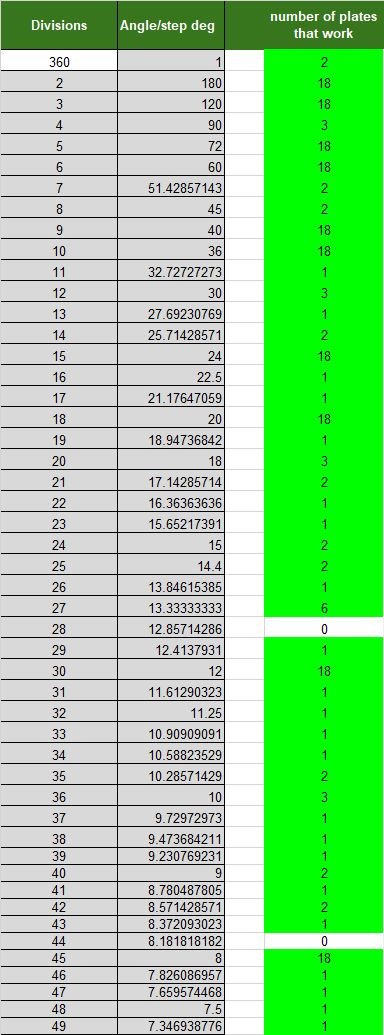
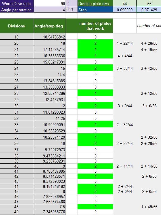
Second - you have a 41T gear in the train which is a prime number and therefore complex to manufacture needing an accurate progression of 8.780487805° between each tooth. I don't have a solution in my gear-hobber tables for 41T - but I have made one by engraving a sheet of Tufnol on my CNC machine.
You also have a 117T and, whilst not prime, is odd with only 4 factors, needing a progression of 3.076923077° and 29T needing 12.4137931°. All OK if you have dividing plates with 29, 41 & 117 holes but again I don't have a solution for either of these; I can get 29.0013986 🤣

Now I must say that I think that you have done a fantastic job on this engine so I'm not decrying your efforts in any way, but there is a solution to your 10:1 which is a much better 'fit'.

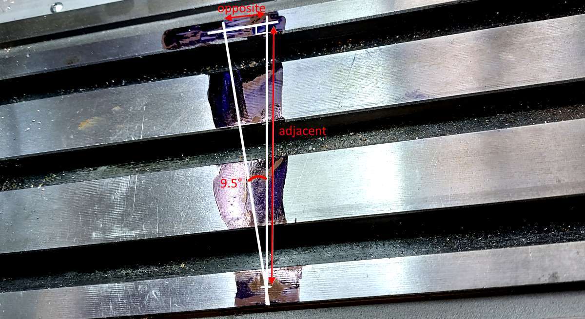
I have had to work from the photo you posted and used that to 'scale' my drawing. I have to assume that the 67.575 measurement is sacrosanct and I can only guess at the absolute centres of the two bearings from your low-res image so you will see from my drawing that I'm out on that by 0.0183mm which will have some bearing upon the dimensions for the location of the lay shaft but I doubt that they will be too significant.
View attachment 129983
This solution uses tooth counts which are easily manufactured - 25, 48, 100 & 120. Incidentally, I have used a 'clearance' - between meshing gears - of 0.1mm so the physical properties of the gears is :
View attachment 129984The 'normal' terms used to specify gear dimentions are Pitch Circle Diameter (PCD) and Outside Diameter (OD) rather than 'radius' or 'Tip diameter'. 'Centre Distance' is of course of prime importance.


I would presume that the ideal location for the layshaft would be in line with the 120T gear - which would be 90° to the bottom edge. My calculations put it at 89.48079° and to make that any more meaningful I would need very accurate information as to the precise distance between the two bearings measured parallel to the bottom edge of the Brass plate - this is the 23.2122 measurment in my drawing which is a simple scale measurment of your photo so subject to all manner of possible errors. 😖 Changing the clearance from 0.1 to 0.2 would have a significant effect upon that angle. It may well be inconsequential but when designing clocks (or any gear train) I try to stick to easily achieved 'in-line' or 90° locations wherever possible.
Whats the problem with prime number gears ?
If you have the correct OD of the blank, the correct cutter and set your dividing head correctly - where is the issue ?
 
Whats the problem with prime number gears ?
If you have the correct OD of the blank, the correct cutter and set your dividing head correctly - where is the issue ?
The issue is purely down to the fact that Prime numbers give less options or require more generating gears to be available. I will say that my opinion comes from the fact that I use a Gear Hobber rather than a Dividing Head but even then how would you cut a 41T Gear if you didn't have a 41 (or 82) hole plate?

If you had plates with every hole count from 5 to 120, the options open to you for (say) a 28T gear is 15, change that to 29 and the options drop to 3. This assumes that you have a 40:1 ratio Dividing head, if you have a 60:1 the 29 options drop to 1. In real life a well equiped workshop might have 6 or 8 plates with 5 or 6 hole counts so something between 30 & 48 choises (rather than over 100) and, whilst I agree that most of them are likely to be Odd, if not Prime, there is still a limit to the number of options.

Bottom line is that by chosing Prime Numbers for Gear Teeth you are restricting your options as to means of manufacture. I don't say that the issues are insurmountable, just restictive.
 
I spent Saturday afternoon adding the beading to the edge of the tender. It's not perfect as half-round brass beading tends to rotate as you try and bend it flat around corners. I should have made some jigs.

tender-bead-07.jpg


I also used some very old flux, it worked perfectly considering just how old it is....
fluxite-03.jpg

I posted the image from the tin of fluxite as it just makes me smile.
Bought a tin of that about 2 years ago in a very old fashioned shop in west Clare here in Ireland.
 
The issue is purely down to the fact that Prime numbers give less options or require more generating gears to be available. I will say that my opinion comes from the fact that I use a Gear Hobber rather than a Dividing Head but even then how would you cut a 41T Gear if you didn't have a 41 (or 82) hole plate?

If you had plates with every hole count from 5 to 120, the options open to you for (say) a 28T gear is 15, change that to 29 and the options drop to 3. This assumes that you have a 40:1 ratio Dividing head, if you have a 60:1 the 29 options drop to 1. In real life a well equiped workshop might have 6 or 8 plates with 5 or 6 hole counts so something between 30 & 48 choises (rather than over 100) and, whilst I agree that most of them are likely to be Odd, if not Prime, there is still a limit to the number of options.

Bottom line is that by chosing Prime Numbers for Gear Teeth you are restricting your options as to means of manufacture. I don't say that the issues are insurmountable, just restictive.
Hello J-G and all,

Thought I would share the calculations for the HV4 rotary table and dividing plates. The excel calculation sheet is available as a free download: workshop calculations The full sheet allows you to enter the division plate divisions and then highlights the options that work for divisions up to 200.

The Warco HV4 and dividing plates is quite good as it comes with 3 plates and they have divisions of: 15, 16, 17, 18, 19, 20, 21, 23, 27, 29, 31, 33, 37, 39, 41, 43, 47 and 49 and thus give you the list as shown below:

HV4-options.jpg


Sadly 28 and 44 are missing. A quick play with the sheet and if I make up a 44 and 56 hole plate I can solve this (obvious really)

HV4-options-new-plates.jpg


I know someone is going to point out the small errors at 6 decimal places, but for me this works. Please do download for free and have a play or use or comment. Thanks, Nigel
 
Back
Top