Just stumbled across this thread, quite ridiculous what somebody can achieve with enough skill, patience and determination.
Not just the model making but all the theoretical analysis on the boiler design too, just stunning.
I would be interested to know what your actual job is assuming it is something to do with the model making? I'm curious because if I was to create something like this project I would want to be paid about £20k for it and I'm pretty sure nobody is going to pay that, even though it's probably worth that much in ingenuity and hours. Or maybe somebody does pay that, I have no idea. Just curious how this stuff works commercially. You deserve every bit of good fortune you get though! Amazing.
Martin
Hello Martin,
Thanks for the kind words. Until very recently I have headed up a battery research and development team. Now I have more time to spend on model making which is great. I've been model making for a long time having started using a lathe when I was 11. However, my background is a degree in physics and from this I worked in acoustics for many years before designing a number of hybrid concept cars. Hence moving to battery research and design. So, I'm a self taught model engineer and I just really like understanding how things work and how to make them.
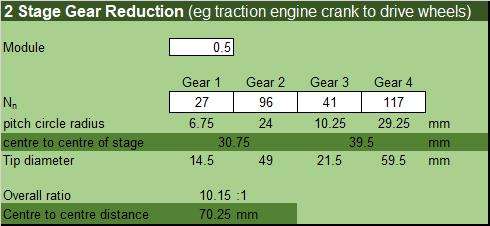
I haven't added up the hours that have gone into this model, but far beyond anything I could charge for. I will develop a set of plans for the engine as I think others will want to make it. Although I still have a lot of parts to design and make before I finish. Including a working differential that is being designed in my head at the moment.
Thanks, Nigel
 that won't be easy but I'm sure you will enjoy it. Looking forward seeing it all finished.
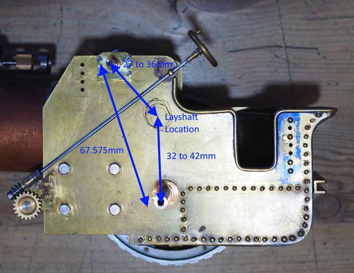
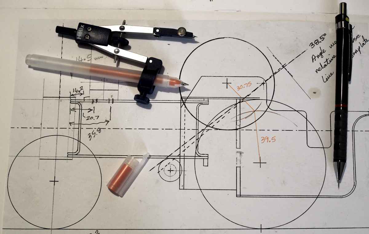


 Changing the clearance from 0.1 to 0.2 would have a significant effect upon that angle. It may well be inconsequential but when designing clocks (or any gear train) I try to stick to easily achieved 'in-line' or 90° locations wherever possible.