info requested on union graduate bowl lathe

UKworkshop.co.uk

Help Support UKworkshop.co.uk:

This site may earn a commission from merchant affiliate links, including eBay, Amazon, and others.

graduate_owner

Established Member
Joined
5 Aug 2012
Messages
2,246
Reaction score
79
Location
Llandeilo
Hi everyone,
I’ve just bought a Graduate bowl lathe to go with my old Myford ML8. I’ve been scanning through the forum entries here and have found comments such as ‘The lever to tilt the motor has an adjuster on the tilting mech, it is a long thin hexagon shaped bolt’

There doesn’t seem to be any such mechanism on my lathe. There is, however, a small (about 3” long) spindle with a red knob on the side located inside the motor housing area, but it doesn’t seem to do anything and can be slid out easily.

Can any readers advise on these issues.

Also I’ve seen graduate bowl lathes with drilled holes where a right hand (inboard) bed could be fitted – but no bed. Mine has no holes. Are graduates normally left undrilled?
Any info would be gratefully received, as would any info on graduate parts for sale – especially chucks or thread adaptors to enable me to use my Myford chucks on the graduate.
Thanks
 
Hello, it the tilting mech should slide in and out but it sounds like you are missing the long hex nut. This is to adjust the tension. Could you take a pic of the inside for us. When the wife gets off the cpu I will paste a link on here to help you out.
Hole wise I thought they were all drilled and threaded. I surpose the dedicated bowl lathes were not. You have got a fantastic machine and with a bit of fiddling about it will last forever.
Rich
 
As Rich says it is for tensioning and should slacken the tension so that the belt can be changed to a different pulley.

I bought a bowl lathe and went through the motions to get a bed for it. I have changed my mind after a lot of research. Originally they were drilled and tapped for a bed to be added and each bed was fitted and lined up exactly and two metal dowels were put in to get exact alignment again if the bed was taken off for transportation. There is a company near Manchester who will fit a bed for you, either buying it from them or sourcing your own, but unless you have deep pocket or are lucky getting a cheap bed, leg, banjo and tailstock, you would be better off buying a graduate with the bed you want. It sounds like you have one that wasn't even drilled and tapped for a bed, so must have been a dedicated bowl lathe, but usually even those were drilled and tapped.

Regards
Peter
 
http://www.woodturninglathes.co.uk/Headstock.html
you need to check that you 44, 45, 46

It is a but of a pig to put it all together, but not that hard.

This site is a one stop shop for what you need, pricey but everything is in one place. I bought my recon short bed lathe from them and they were brilliant!!!!!!!
I have also got a long bed (different parts from ebay.) Had a few problems wiring it up with a different motor, phoned lee at LRE and he sorted out straight away.

Still post a pic if you can, it would be interesting to see
Rich
 
Many thanks to all who replied to my request for info on the union graduate.
Regarding the holes needed to connect to an inboard bed - (you won't believe how dumb I feel in admitting this) - as soon as I cleaned off the accumulated caked on debris, I found them!!

I will post photos of the motor housing ASAP.

K
 
Hello Graduate Owner,
The hex rod referred to has a RH thread on one end and LH on the other with lock nuts. Turning this rod makes it longer or shorter (because of the LH and RH threads working in opposition) and provides the fine adjustment for belt tension. The cam mechanism (ball and lever) provides rapid up and down movement of the motor platform for belt/speed changing. Some Grads have a round rod instead of hexagonal with a hole through for a tommy bar. I am not a million miles from you so will send a PM should you wish to contact me for more help.

Regards, Tudor
 
Hi again Newbie,
My graduate has no rod for tensioning and the cam mechanism just sits in a hole in the casting and doesn't do anything. I think I need to look at a working mechanism (such as yours!!)
I'll be in touch.

I've only just figured out what a PM is, but I don't yet know how to send one - working on it.
K
 
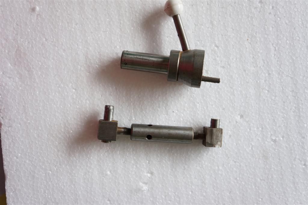
This is what the turnbuckle mechanism looks like
DSC00961Large.jpg


DSC00962Large.jpg


Hope those help

Ian
 
Thanks Ian,
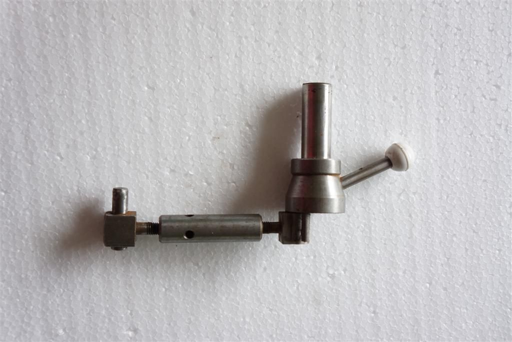
those photos make things a lot clearer. I may be able to sort out my lathe now. The belt has no tensioning other than the weight of the motor, and the motor mounting plate actually rests on the switchgear box, so it isn't properly tensioned anyway. It has been used for sanding, so I suppose there was no need for a really well tensioned belt as no-one was taking deep cuts into large bowls.

Do you really have FOUR graduates? Wow!!

K
 
OK, so now I see what's going on with my graduate. The motor must have been changed, and the replacement has a capacitor which must be in a different position to the original. The end result is I can't raise the motor mounting plate to align up with the cam assembly because the capacitor hits against the side of the lathe body.

I don't know if it's worth sorting this out because it will mean changing the motor and getting a shorter drive belt (chronos do a powertwist belt for 24.50 per metre, so that's £50 to start with. Other suppliers I've browsed for charge more).

The lathe came with a sanding attachment instead of a tool rest. I'm currently machining up a reducing collar to enable me to use my Myford rests. Then I can try turning a bowl and will know if the belt slips when I'm turning.
If it does then I will need to shorten the existing belt which is a link belt (black) and seems to have links which are of the 'not-easily-removable' type. I may try hacksawing and rivetting, but if that fails and I ruin the belt then it's back to spending £50 again. I'm not sure it's worth the risk and effort unless slipping becomes a real problem.

By the way, does anyone have a sanding table? Mine seems to be a genuine Graduate accessory as shown in their handbook - a solid casting which has a knurled nut on each side and which look as if they are meant to allow the table to be tilted, but it doesn't seem to work and I don't want to damage things by forcing. If anyone has this type of sanding table which does actually adjust could they offer some guidance? Otherwise it may be fetch the hammer and see what happens with some (very) gentle persuasion.

K
 
Pull the knurled knob out first about 12 mm or so then loosen the nut with a spanner then you can move to the desired angle then tighten nut and push in knurled knob

if knob wont come out remove the slotted screw from the mitre slot and lubricate down hole without screw the knob will pull fully out

You have 2 knurled nuts? Well the one you pull is the left hand one when mounted on your tool rest right hand one is usually a nut about 22mm across flats
 
Just put a standard drive belt on measure with string how long you need and order off eBay about £7 should do it...you could move the capacitor so it doesn't foul the body ?
 
Hi flh801978, and thanks again for the prompt reply and helpful info.
Regarding the sanding table, yep - the knurled knob pulled out (after a few taps with a rubber mallet) now I'm working in cleaning and oiling that so it works with hand power only. And, yep, there's only one knurled knob - the other looks similar but is smooth. I blame my ageing eyesight.

Regarding the motor, the capacitor is encased on a metal shroud bolted onto the motor frame. It's so cramped in there that I can't really see what's going on, but I'm a bit reluctant to remove the shroud and try to re-locate the capacitor as I think it may be a bit of a performance. I have a 3-phase inverter for some of my other kit so I'm thinking of replacing the motor with a 3-phase one and that will give me variable speed control. I've done that on my Myford ML8 and it really is brilliant, especially when you start with some wood that is off-centred, because the really slow speeds available cut down on vibration. Getting it in that confined space, though!! Perhaps I could winch the beast off the floor, or onto it's side, and install the motor from underneath

Finally, regarding the drive belt. If I use a continuous Vee belt then I will have to remove the headstock spindle to get the belt over the pulleys - I think that may be a performance as well, although not having done it before, I don't really know. That's why I was thinking of a link belt that can be undone and simply threaded around the spindle. The trouble is they are really expensive.

Do you know of any other possibilities?, or is it really easy to remove the spindle anyway?

K
 
Spindle removal to fit a belt it a 10 minute job and variable speed is the best modification you can make
motor removal is easy just remove the grub screw and lock nut from the pedastal at the end of the motor pivot spindle inboard end...slip the spindle towards the outboard end ( there may be a collar too on the shaft between the motor legs motor then slips out through the door
the link belts are noisy in use where a standard belt is quiet and is better for the pulleys too


to remove spindle just undo fully the grub screw ( imperial size) in the collar on the outboard side ( sometimes 2 grub screws one on top of each other)

then drift the spindle with a copper mallet and a spindle of hard wood towards the inboard side just enough to slip the belt by the spindle...its tight but can be done without loosening the pulley.
replace the belt and drift back in replace the collar and tighten the grubs up

Ian
 
Hi flh801978,
once again, a really helpful and amazingly fast response.

If it's that easy to fit a drive belt then I'll give it a go, likewise with removing the motor. I was a bit dubious because I had similar jobs to do on my ML8. Some years ago. I failed to move the headstock spindle (there may be a technique that I don't know about) so bought a link belt. Removing the motor was an absolute nightmare, although not having the proper motor mounting plate may be the reason. When I fitted the 3 phase motor a few months ago, I was on my knees fighting with the thing and trying to support the weight of the motor for about 2 hours. In the end I used a car jack to support the motor while bolting it into place, but still had an aching back for a few days.

Once again, many thanks for the help. I'll keep you posted on progress.

K
 
Next question regarding the Union Graduate - I'd like to know what the taper is in the outboard side of the headstock spindle?
I know the inboard is 3MT, but the outboard is smaller than 3 MT and larger than 2MT.
Anyone have any ideas?

K
 
OK thanks for that. I was thinking to turn up a shaft to go through the headstock with a locking nut on the inboard side, and a ML8 thread on the outboard side, so allowing me to use existing faceplates and chuck. Might work.

Regarding the process of removing the spindle, I have manage to slide it as far as the pulley will allow, but there's not enough clearance to get a vee belt in. I've removed the allen grub screw from the pulley assembly but it won't budge. Is there a technique for freeing this so I can slide the spindle further?
I tried putting an 8mm bolt in the hole where the allen screw was to stop the pulley from rotating, and then turning the spindle with a spanner. The bolt just bent. I don't want to risk damaging the threads in the pulley so I've stopped that approach. Tapping the spindle with the pulley against the casting hasn't shifted it either.
Any suggestions?

K
 
Place a block of wood against the inboard headstock area for the pulley to rest against ....then drift the spindle that bit more...it will be tight...theres sometimes 2 grub screws in all holes in graduates..pulley will be tight if its not been removed before , you can try warming gently with a blowtorch.

as to fittings on the outboard end remember that as standard they are LHT But sometime ago one rebuilder offered a spindle with both ends RHT and the motor span the right way as you placed the end cover over the opposite end that you planned to use,, used a microswitch to sense
ian
 
Back
Top