Garden waterwheel

UKworkshop.co.uk

Help Support UKworkshop.co.uk:

This site may earn a commission from merchant affiliate links, including eBay, Amazon, and others.
Cheers Mike. It's good to hear someone talking from experience.
I'm probably getting a bit ahead of myself but do you think it'd make much difference what angle I put the slats at ?
189ba68f2ef95be8b9f545efae7059c4.jpg

I've got a large amount of iroko off cuts but the thing is they are all quite narrow. I was thinking of t &g boarding around the entire inner circle, then have the slats butt up to that.
7006b11972a85e3c4890f59dc97097e0.jpg

Thanks
Coley

Sent from my SM-G900F using Tapatalk
 
Hi Coley
I did much the same as you suggest but I housed the ends of the circle of boards into a groove in the inside face of the circular discs. Each of the boards is rebated on both edges where they meet one another and the groove was wide enough to easily take the straight bits of board. Mine was a pig of a job to assemble and I resorted to a piece of elastic to hold the bits together while the second disc was put on. The slats to hold the water were slid into routed grooves after their inside edges had been beveled to fit the line of the cylinder. It's tricky ensuring that the two discs and their grooves are exactly opposite one another to get the slats level. I will email you a photo of a disc I managed to ruin by routing a groove in the wrong place. It shows the angle I used for the slats which may be helpful. I used west epoxy to glue the boards and slats to the discs but didn't glue the boards together. I think your method of fitting the boards to the inside edge may be much easier to do and every bit as good.
Mike.
 
I reasoned that the slats would be best if they were horizontal and shedding the last of the water when they reached the 4.30 position on the clockwise turning wheel. I cut the grooves for the slats by fitting the disc onto a jig which allowed it to rotate under a hinged jig that guided the router. As you can see not everything went to plan, I think I picked up the wrong mark and cut a groove in the wrong place, the result being a carefully crafted piece of firewood!
Mike.
 
Mike Jordan":1ol3j3kg said:
Hi Coley
I did much the same as you suggest but I housed the ends of the circle of boards into a groove in the inside face of the circular discs. Each of the boards is rebated on both edges where they meet one another and the groove was wide enough to easily take the straight bits of board. Mine was a pig of a job to assemble and I resorted to a piece of elastic to hold the bits together while the second disc was put on. The slats to hold the water were slid into routed grooves after their inside edges had been beveled to fit the line of the cylinder. It's tricky ensuring that the two discs and their grooves are exactly opposite one another to get the slats level. I will email you a photo of a disc I managed to ruin by routing a groove in the wrong place. It shows the angle I used for the slats which may be helpful. I used west epoxy to glue the boards and slats to the discs but didn't glue the boards together. I think your method of fitting the boards to the inside edge may be much easier to do and every bit as good.
Mike.
I received the pic Mike thanks. It looks like from your pic you had 12 slats. I've got enough dog-ends for 16 so that might be enough.
Thanks for your detailed pics, it's comforting to follow an already working design.
Hopefully I'll get a few hours on it tonight.

Coley
 
Mike Jordan":2gbnn37n said:
I reasoned that the slats would be best if they were horizontal and shedding the last of the water when they reached the 4.30 position on the clockwise turning wheel. I cut the grooves for the slats by fitting the disc onto a jig which allowed it to rotate under a hinged jig that guided the router. As you can see not everything went to plan, I think I picked up the wrong mark and cut a groove in the wrong place, the result being a carefully crafted piece of firewood!
Mike.
It's not the most straight forward things to route though to be fair [WINKING FACE]
You've just solved how to route the slats in
68ae6ff86e939480a4453a80d0cb8ab6.jpg

Pivot in the middle and a guide bush following a groove on the jig should do it.
I'll double check the angle and the 4.30 thing before I start routing.
Cheers

Coley
 
Just routed the inside
d32891fb6a4c8c17021f3ca91ad74595.jpg

Measured the diameter by using masking tape cause it's so humpy bumpy.
e584ef97848bbf1b8f7e24aa796057ef.jpg

The length on one is 3958mm and 3971mm on the other. By my reckoning that's 1260 and 1264 diameter. The wheel rings are only for looks more than anything. I think I might have to rout them differently though. Perhaps allow em 3mm diameter slack so they'll go on with ease :?

Coley

Sent from my SM-G900F using Tapatalk
 
ColeyS1":sat49mw1 said:
Daft question but would the gearing just slow it down by adding a certain amount of friction/resistance?

Gearing slows down or speeds up your system by having gears of different size. If you have a drive gear with ten teeth meshing with an attached gear with twenty teeth (and thus twice the circumference), then the attached (teeth in mesh) gear will rotate at half the speed of the drive gear. The reason being that when the drive gear makes one full rotation it moves ten teeth, which means that ten teeth move on the attached gear... but ten teeth on the attached gear is only half a rotation. So for every full rotation the drive gear does, the attached gear rotates half a rotation.

For example, if your water wheel is moving three times faster than you want the figures to move, then you could have a small drive gear attached directly to the wheel (e.g. with 7 teeth), and a larger gear that has three times as many teeth in mesh with the drive gear (e.g. with 21 teeth), then the elliptical wheel to drive the figures gets mounted to the same shaft as the larger gear. The same principle is commonly used in pillar drills to change the speed by having the drive belt spanning differently-sized wheels.

If you want to slow the speed down without having a gigantic gear taking up space, you can chain multiple gears to slow the movement down in steps. So if you want to slow down by a factor of four but a 28-tooth gear is too big, then you can have shaft 1 contain your water wheel and a 7-toothed gear in mesh with a 14-toothed gear on shaft 2, then at the other end of shaft 2 there's another 7-toothed gear which is in mesh with a 14-toothed gear on shaft 3, and at the other end of shaft 3 there's your elliptical wheel. Shaft 2 moves at half the speed of shaft 1, and shaft 3 moves at half the speed of shaft 2... and thus one quarter the speed of shaft 1.


There's a handy online tool on Matthias Wandel's site for printing out templates to cut gears from wood: https://woodgears.ca/gear_cutting/template.html
Just remember that - friction in the system aside - whatever factor you decrease the speed by, you increase the torque by. So if you slow a gear down to one quarter the drive speed, it's four times more likely to break your finger if you stick it in the wrong place. ;-)
 
Ta for the explanation regarding the gears. Perhaps I'm just being a numpty but I don't understand how adding gears could alter the speed the waterwheel spins at ?
Say I've got a pond pump that can move 10000litres an hour- that's fixed, I can't alter the flow. I've also got a wheel with certain size buckets and a certain weight, I can't easily alter that. If those 2 things cause the waterwheel to spin too fast, adding cogs/gears would only control something I was using the waterwheel to drive ? I don't need this to drive anything, I just want the wheel to turn and to make a splashy sound.
While looking for waterwheel pictures last night, I stumbled across a handy website. This guy sells bit to make your own waterwheel. One of the things he sells, is a brake to slow waterwheels down.
16145a2820b7c3267fe2ad906404007e.jpg

Looks like a fairly straightforward way to add friction if required.

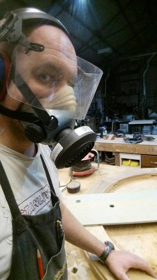
Been coughing like a champ since using this awful iroko again.
d46f36675e6d0ff357cfe69dddf90744.jpg

Even wearing a mask, with air filter running, my lungs feel like I'm smoking 20 cigs a day. So glad I stopped using this and switched to sapele/utile for most jobs.
5f53726bd0bdefae53db0240d90e11d8.jpg

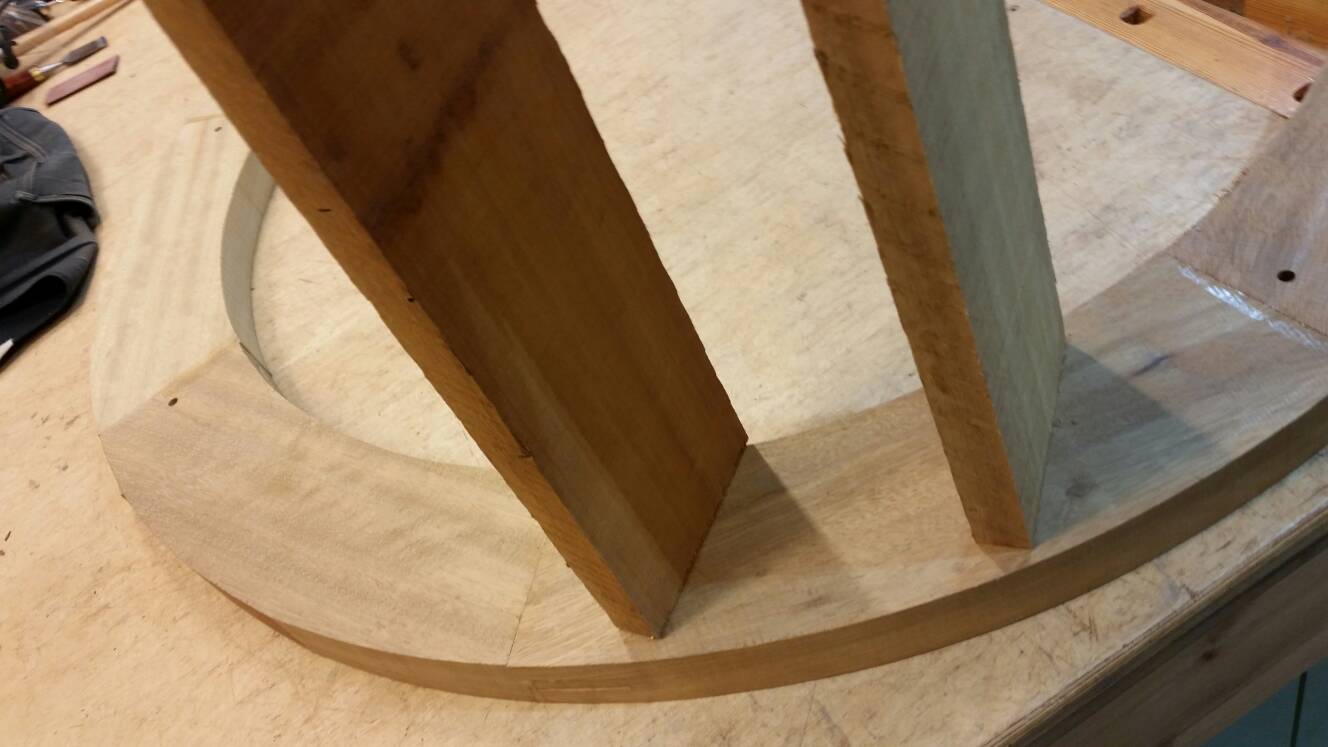
I did a test fit with the metal rings. As you can see they really are an awful shape
346bc074c191c714f3f7a4dbfbfa2db3.jpg

One of them went on relatively easy, the other I think I could get on, but don't think it'd come off again so I'll leave that until it's ready to stay on permanently. I need to flush trim the outside of the wheel to the newly router diameter. I'm hesitant to use a router cutter cause iroko being so abrasive just kills them. I might use the spindle moulder and a rebate block instead if I can manage the awkward size.
e241e4060ed51650e11fde0f36603e78.jpg

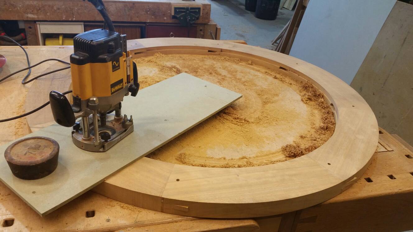
I hot glued the wheel to my bench to do the routing, it's safe to say the hot glue did it's job, almost too good. I've ripped the ply bench top in a few places trying to remove it.
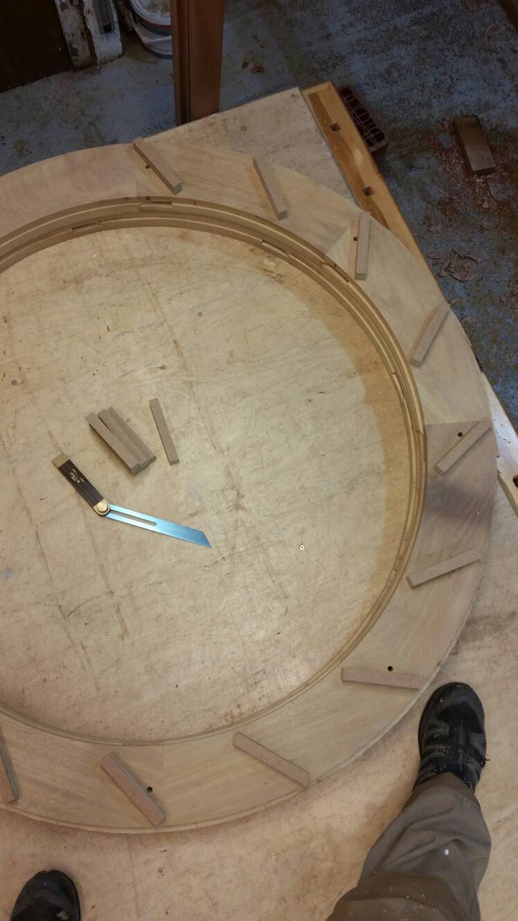
The worry thing is the waterwheels getting smaller the more I work on it.
1bb4123eab138846d7b991122fd8a45e.jpg

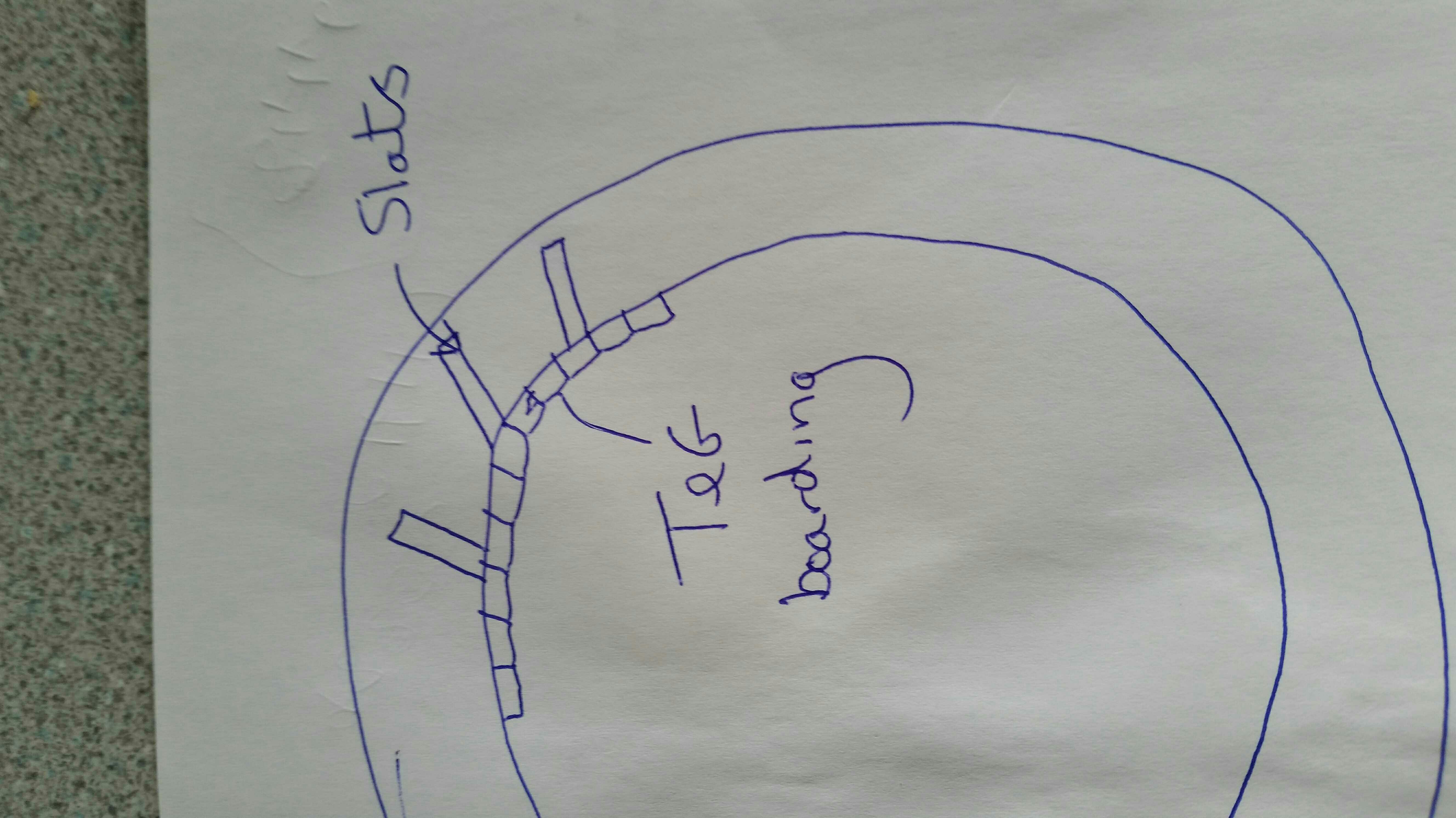
The mdf fins are the maximum size I could get from my iroko dog ends. I like how it might look, just hope I'll have enough flow for it to turn.
Mike, does the bucket position seem about right regarding the 4.30 position ? I've put my foot where I think it looks like it should start emptying.
Cheers guys
Coley

Sent from my SM-G900F using Tapatalk
 
Hi Coley
That looks great to me, I agree about the need to dodge the Iroko dust, the truth is that it's only great advantage is that it lasts for a huge length of time in outside use.
Mike.
 
Thanks Mike. Do you think the pockets look big enough though ? I guess it's the flow of water against the first one it hits that causes it to turn, not the pockets filling up ?

Coley
 
It's the weight of water on one side of the wheel that makes it rotate, each litre is a kilo so not a lot is needed to make it go. I've never dealt with a wheel that size but if we assume that it's well balanced and running true I think it will work brilliantly with just a small flow of water. It's the total weight of all the pockets contents on the descending side of the wheel that provides real power. Isaac Newton is in charge of that bit of the operation!
I'm not sure about the steel tyres, if they are not a good fit and run as a true circle they may not add to the appearance.
It's looking good so far. Mike.
 
Mike, I appreciate hearing your thoughts. I don't feel like I'm working on my tod making it.
To be honest I hadn't considered how the steel rings might look when the wheels spinning. It's relatively flat, perhaps when the wood swells a bit it might even out the humps. I'll take your advice on board and not screw them on till I see it spinning.
I flushed trimmed the outside earlier
ecd9188ed70fb9a307b1f64a74a19683.jpg

The routed bit ran against the bar. Each revolution it trimmed it closer and closer till it was flush
1bddf87e0096820ba1f08ab7a93a4313.jpg

A while ago I machined a load of 40mm dowel. I planned on making something from it but this is a little more urgent in terms of making space in the workshop. I can't decide whether I should splash the cash on some timber to make the spokes prettier or just use em. The latter's what I'm leaning towards
412fd4ffbb71d214c730f90e3819ed8b.jpg

3f252ab6912a5998c89cb97c80d045a5.jpg

The hubs the other issue at the moment. If I had another pulley, like the one in the pic (it came off the saw shaft) I think it'd be fairly easy to weld some pieces of metal for the spokes to bolt on. It'd be a lovely fit on the shaft....If only I had another !!!!
I'm gonna try for a big push on Saturday. It'd be nice to think the wheel being assembled at the end of the day.

Coley

Sent from my SM-G900F using Tapatalk
 
ColeyS1":36wxdyr7 said:
Ta for the explanation regarding the gears. Perhaps I'm just being a numpty but I don't understand how adding gears could alter the speed the waterwheel spins at ?

Ah! Sorry, I got you mixed up with Mike Jordan for some reason!

If you want to slow the speed the wheel spins at, then you need to introduce some resistance into the system. Gears aren't necessarily the best option there, but there is a way to shoe-horn them in if you fancy a bit of extra engineering challenge!

(I suppose you might want to avoid something simple like a screwed-down block on the principle that anything that introduces friction can potentially wear and/or make unpleasant noise, but realistically it's probably a perfectly good solution.)

If you follow the gear-train approach in the opposite direction, from big to small, then you end up with a small gear which has less torque than the drive gear but moves faster. If you put paddles on that as well and dip it in water somewhere (e.g. at the same level as the water under the wheel, but inside the housing?) then it will introduce a bit of resistance from trying to move through the water, but not enough to overcome the drive of the main wheel driven from the water falling across it. You could then adjust how much resistance it offers by varying the gear ratios or simply moving the gear into or out of the water a bit more. The energy has to go somewhere, but with this approach it gets dissipated into more splashing noises that probably won't be audible over the noise of the main wheel turning.
 
Hi Coley
I think the round spokes will look good. How will you fix the spokes to the outer rim, machine a flat on the outer ends of the spokes and screw through?
I've used the last of my teak off cuts for another small wheel to have another go at a water mill, I have some ideas for moving figures using magnets and more involved movements. If they work out I will send you some pics.
Mike.
 
JakeS":2ti586lu said:
ColeyS1":2ti586lu said:
Ta for the explanation regarding the gears. Perhaps I'm just being a numpty but I don't understand how adding gears could alter the speed the waterwheel spins at ?

Ah! Sorry, I got you mixed up with Mike Jordan for some reason!

If you want to slow the speed the wheel spins at, then you need to introduce some resistance into the system. Gears aren't necessarily the best option there, but there is a way to shoe-horn them in if you fancy a bit of extra engineering challenge!

(I suppose you might want to avoid something simple like a screwed-down block on the principle that anything that introduces friction can potentially wear and/or make unpleasant noise, but realistically it's probably a perfectly good solution.)

If you follow the gear-train approach in the opposite direction, from big to small, then you end up with a small gear which has less torque than the drive gear but moves faster. If you put paddles on that as well and dip it in water somewhere (e.g. at the same level as the water under the wheel, but inside the housing?) then it will introduce a bit of resistance from trying to move through the water, but not enough to overcome the drive of the main wheel driven from the water falling across it. You could then adjust how much resistance it offers by varying the gear ratios or simply moving the gear into or out of the water a bit more. The energy has to go somewhere, but with this approach it gets dissipated into more splashing noises that probably won't be audible over the noise of the main wheel turning.
Oh I see ! Your solution sounds amazing and would definitely add some interest if the inner part was spinning aswell. I think I'd have a nervous breakdown though trying to put it into practice :)
I'm fascinated by gears and cogs. I like the steampunk look of things but trying to find second hand cogs that'll work with others make most ideas not possible. You seem to have a good understanding of them. Is it something you've picked up along the way ?

Coley
 
Mike Jordan":20bg42nm said:
Hi Coley
I think the round spokes will look good. How will you fix the spokes to the outer rim, machine a flat on the outer ends of the spokes and screw through?
I've used the last of my teak off cuts for another small wheel to have another go at a water mill, I have some ideas for moving figures using magnets and more involved movements. If they work out I will send you some pics.
Mike.
Exactly that Mike, I think that would be the easiest option. I like how you've took the motion from the waterwheel to operate things.
Forgot to mention, the dog/cat house in your pic also looks great. What other stuff do you make ? - not that I'm thinking of borrowing some more of your ideas ;) :)

Coley
 
Hi Coley
The cat house was featured in an article I wrote for good woodworking so it's already public property, I should be able to find a set of plans if you needed them. I've knocked the magazine articles on the head for now since two of the magazines like to reuse your work without payment. The exception being the WaterWays World magazine they had one of my articles each month for more than two years, I have since turned a number of the article into a book, it's failed to make my fortune but is still selling on Amazon. My friends in the boat fitting game snatched a copy each and I have found my designs being made in lots of places!
The prices charged by boatyards would sometimes take your breath away, so I still make a few bits for local fitters.
Mike.
 
Whats the name of your book, if you don't mind me asking ? Does seem a bit naughty that they haven't been paying but happily been publishing your material.
After you mentioned about the buckets filling to turn the wheel, I found this picture
8eec50af750797dfa5014d4e8ef920cc.jpg

Looking back at the picture of my layout I think I might need to make the buckets bigger....somehow. The ones in the above pic look like the're really brimming, mine look tiny in comparison.

Coley

Sent from my SM-G900F using Tapatalk
 
Hi Coley
I think that times are not so good in the world of magazines generally, subscriptions are a discressionary purchase and people have been looking to save money and just buy the occasional magazine. The net must also be a factor, you can find plans and instructions for all sorts of things totally free. It doesn't seem to have registered with the magazines that they are contributing to the decline by posting articles on line. The book is "Narrow Boat & Dutch Barge Joinery Designs for Boat Fitters" ISBN 978-095768240-5
The top wheel design looks closest to ours, the others look as if they hold a lot of water and deliver a lot of power. How wide do you intend to make your wheel?
Mike.
 
I don't think you will need to do it but it would be possible to add a retaining lip to the front edge of each compartment. We are after all only spinning the wheel for ornamental purposes rather than delivering power.
Mike.
 

Latest posts

Back
Top