Ed Bray
Established Member
How I make my Pressure Relief Valves with easy reset (to prevent either a Cyclone or Dust Collection Vessel collapsing inwards if delivery hose gets blocked).
I decided to try to document how easy it is to make one of these, and it will protect your valuable Cyclone or Dust Collection Container should a blockage occur. I thought it might take an hour or two, but documenting it, making it, photographing it and processing the photographs has taken about 6 hours #-o so I hope someone finds it useful :!:
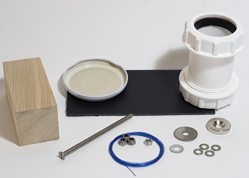
Items required:
40mm PVC Straight Coupler (This makes the body of the valve). (from Screwfix a single FloPlast WC08 costs £1.59).
Ferrous Metal Jam Jar lid (this makes the valve flap).
20mm x 5mm Magnet with 5mm countersunk hole (I used EP374A from e-Magnets UK, £6.50 for 2).
Long Machine screw with Countersink Head, this is to mount the magnet at a suitable distance inside the valve. (I used a 4mm x 100mm Stainless Steel Machine Screw).
3x 4mm Nyloc Nuts (to mount magnet assembly to valve body)
4mm Standard Nut (to mount centre support to machine screw, hard to use a nyloc for this)
4mm washers
Some strong thin sheet (can be Brass, Aluminium or something else suitable strong), I used Brass for mine this is to make the supports for the magnet assembly that seat inside the valve (Initially tried plastic card as photo but this had too much play so went back to brass).
Some Nylon Fishing Line of 30-50 lb breaking strain (to make your valve able to be re-set without removing the lid of your collection vessel). 3ft is plenty, (this is not essential for the relief valve to work but does make life a lot easier).
Small piece of wood with a hole in it to act as a puller to reset the valve, (some form of toggle works well.
Tools required:
Fine bladed Saw (to remove flange from one of the Coupler’s Compression Nuts) to make an adjustable connector for the valve. (I used a Multi Saw for this with a fine blade).
Some means of cutting sheet material I used a large hacksaw to cut 2x 12mm brass strips then rounded the ends on belt/disc sander to get the required fit..
Internal Callipers (to measure diameter of valve wall where supports will sit).
Outside Callipers (to measure the diameter of the small flange at the top of the coupler body (above threads).
Some means of cutting hole in lid of Collection Vessel (I used a hole cutter in my plastic lid and a Jigsaw to make the hole in the metal lid).
Screwdriver and small spanners.
Knife or Scissors
4.5mm drill and a driver
1.0mm drill and a Pin Vice.
Steel Rule and Sharpie or Pencil
Sandpaper/File
CyanoAcrylate (Superglue)
Method:
All readings in brackets are for the specific FloPlast WC08 40mm Waste Straight Coupling only.
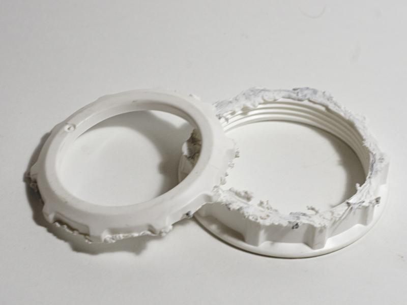
1). Remove both Compression Nuts from the coupler and the two sealing rings and washers, put the compression nuts to one side, the sealing rings and washers are not required.
2). Measure the distance from the internal flange to the end of the coupler, record the reading. (34mm)
3). Using the internal calipers measure the diameter of the coupler just below the internal flange, record the diameter. (43mm)
4). Using outside callipers measure the diameter of the outside of the flange at the very top of the coupler, record the diameter. (50.5mm, call it 50mm for luck)
5) Cut 2x 12mm strips of sheet material at least 53mm in length, mark a line along the length of the brass in the centre of the strip. Mark the centre point.
6). Drill a 1mm hole along the centre line on each strip 15mm from the centre point.
7). Drill a 4.5mm hole in the centre of each strip.
8). Draw a line across the diameter of the Jam Jar lid, mark the centre point, Using one of the cut sheet pieces as a template drill two matching 1mm holes across the diameter of the Jam Jar lid, file/sand the holes to remove any burrs from around the holes.
9). Take one of the compression nuts and using a fine toothed saw, cut off the closed end of the nut (as close to the end as possible). Mount the cut nut onto the coupler with its outer flange facing outwards, sand off the saw waste if any.
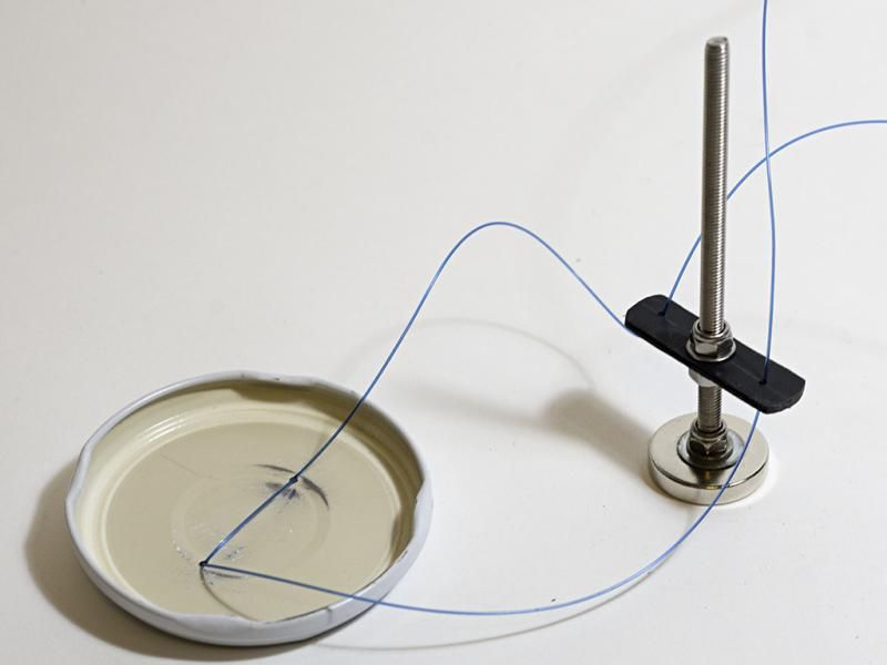
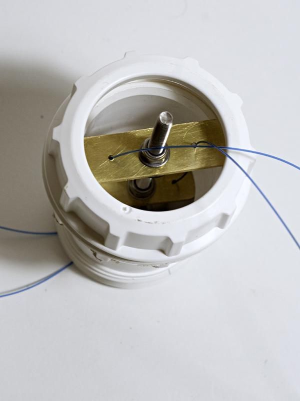
10). Mount the magnet onto the long Machine Screw and using a washer and a 4mm nyloc nut tighten it up.
11) Mount the 4mm standard nut onto the shaft and spin it down the shaft until it is 11mm less from the top of the magnet than the distance from the inner flange to the end of the coupler, then mount a washer to follow it.
12). Mount the smaller of the two pieces of sheet material onto the shaft and allow it to drop until it hits the washer previously mounted onto the machine screw, again follow it with a washer and then a Nyloc nut and tighten the two nuts together trapping the smaller of the two sheet pieces between them. (This should ensure that the magnet is about 3mm inside the end of the coupler when the assembly is fitted into the coupler body.
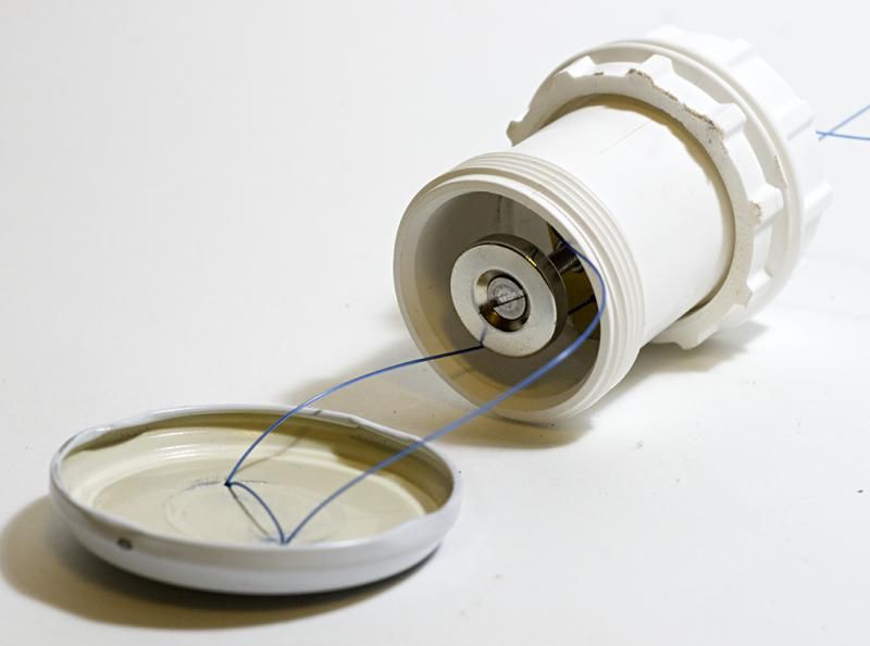
13). Fit the piece of nylon fishing line equalised across the two holes in the jam jar lid and then again feed them through the holes to double them up across the lid, super glue in place to prevent chafing before passing each end of the line through one hole on each side of the smaller sheet piece. Then put the remaining line up through the body of the coupler.
14). Mount the magnet/machine screw assembly into the body of the coupler ensuring that the magnet is approximately 3mm inside the coupler body when mounted with the small sheet piece hard up against the inner flange.
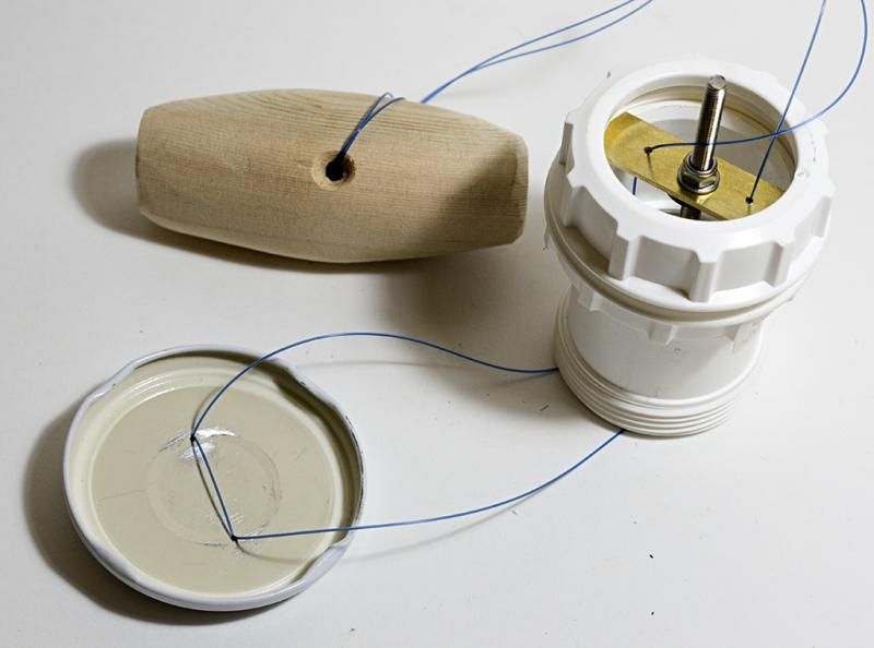
15). Fit each end of the fishing line through the small holes in the larger of the sheet pieces and tie the ends together ensuring that they are as equal as possible.
16). Mount the larger sheet piece on top of the coupler ensuring that the orientation matches that of the lower piece, also the outer edges must not obstruct the threads, drop a washer onto the shaft of the machine screw and add the last nyloc nut, tighten gently to hold the assembly into the coupler body.
17). Pull the fishing line gently to allow the Jam Jar lid to mate with the bottom of the coupler body, it should be held comfortably in place by the pull of the magnet (it doesn’t need to touch the magnet).
18). Cut a (56mm) hole into the lid of your dust collection container, place the assembly through the hole from the inside ensuring that the lower (cut) nut is on a couple of threads.
19). Taking your wooden toggle (or whatever you have decided to use for your pull) feed the fishing line through the hole in the toggle and make a loop, feed the toggle back through the loop in the line.
Completed Relief Valve prior to fitting into Dust Collection Chamber
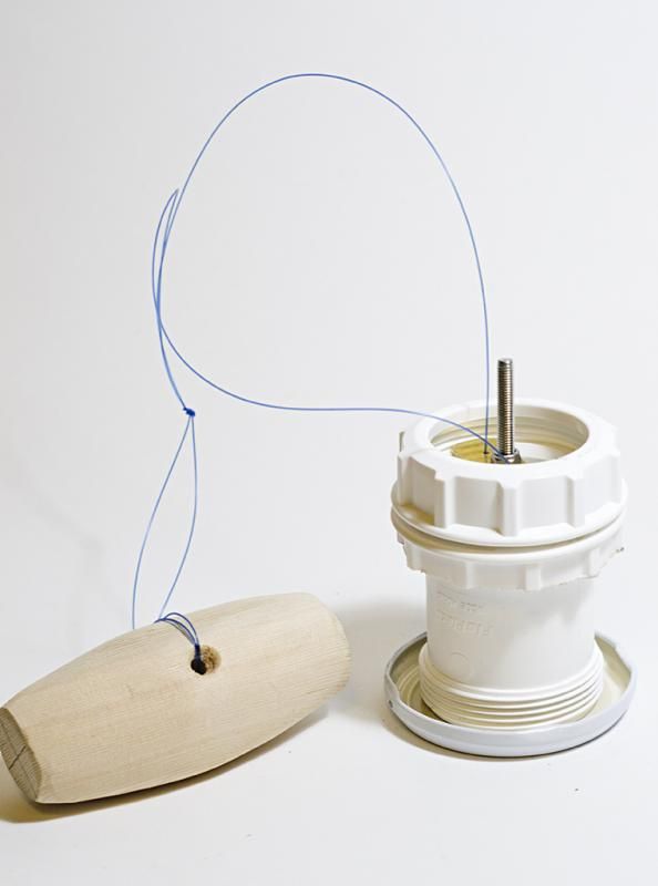
20). Insert the relief valve assembly through the hole you have made in the lid of your Dust Collection Container from the inside and after feeding the toggle through the unused (uncut) compression nut, mount the final compression nut to the relief valve assembly to lock the unit into the lid.
To use, check that the Jam Jar lid is connected onto the base of the coupler inside the Dust Container, if not, pull the toggle to bring it into position. If you would like a softer working valve you can raise the magnet further into the body of the coupler, if you want a stronger valve you can lower the magnet until such time that the magnet is actually touching the Jam Jar lid when it is in situ, but this requires a very large pull to dislodge it and you may find that your container collapses before it is released. Trial and error is the key here and will depend on the integrity of your container/cyclone.
How it works:
Under normal circumstances with the vacuum working the suction is through the Dust Collection Container via the cyclone and the air is exhausted after travelling through the vacuum unit. If the hose becomes blocked the vacuum continues to pull and sucks all the air out of the system causing any structurally weak item to collapse inwards. If the relief valve is fitted, under normal operating conditions the system performs exactly the same as if the valve wasn’t there. If the hose becomes blocked, the vacuum continues to pull and again sucks all the air out of the system until such times as the pressure outside is greater than the pressure inside plus the pull of the magnet then the pressure outside will push the valve flap open allowing the ingress of air and preventing any damage to be sustained.
To reset the system after you have removed the blockage you just need to gently pull on your toggle which will lift the Jam Jar lid back to its normal operating condition. If you use a smaller hose to aid in cleaning up, it can be beneficial to make the valve open by putting your hand over the end of the hose and then continuing to use the vacuum to collect your dust as required, resetting it again before reverting back to normal operations.
Warning: You MUST ensure that there is enough loose fishing line to allow the valve to operate, this only needs to be a few inches of excess loose line before the toggle catches onto the top of the relief valve.
I took the basic design of the relief valve from the Cyclone Central Website ( http://www.cyclonecentral.co.uk/PressureProtection/ ), but then adapted it to be easily reset without having to remove the lid each time, which can be a pain (especially on my metal drum).
They also suggest having a breather hole if intending to use a smaller hose than your vacuum normally uses. This is easily accomplished with a small disc of sheet material which covers a hole and is attached with a small nut/bolt and washers which allows it to pivot, I have done this on my plastic container as this is the most likely to collapse inwards (it did it the first time I tried the cyclone without a relief valve and it tool me ages to restore it to its original shape (I had to use a hydraulic car jack and lots of bits of wood to brace it).
I decided to try to document how easy it is to make one of these, and it will protect your valuable Cyclone or Dust Collection Container should a blockage occur. I thought it might take an hour or two, but documenting it, making it, photographing it and processing the photographs has taken about 6 hours #-o so I hope someone finds it useful :!:
Items required:
40mm PVC Straight Coupler (This makes the body of the valve). (from Screwfix a single FloPlast WC08 costs £1.59).
Ferrous Metal Jam Jar lid (this makes the valve flap).
20mm x 5mm Magnet with 5mm countersunk hole (I used EP374A from e-Magnets UK, £6.50 for 2).
Long Machine screw with Countersink Head, this is to mount the magnet at a suitable distance inside the valve. (I used a 4mm x 100mm Stainless Steel Machine Screw).
3x 4mm Nyloc Nuts (to mount magnet assembly to valve body)
4mm Standard Nut (to mount centre support to machine screw, hard to use a nyloc for this)
4mm washers
Some strong thin sheet (can be Brass, Aluminium or something else suitable strong), I used Brass for mine this is to make the supports for the magnet assembly that seat inside the valve (Initially tried plastic card as photo but this had too much play so went back to brass).
Some Nylon Fishing Line of 30-50 lb breaking strain (to make your valve able to be re-set without removing the lid of your collection vessel). 3ft is plenty, (this is not essential for the relief valve to work but does make life a lot easier).
Small piece of wood with a hole in it to act as a puller to reset the valve, (some form of toggle works well.

Tools required:
Fine bladed Saw (to remove flange from one of the Coupler’s Compression Nuts) to make an adjustable connector for the valve. (I used a Multi Saw for this with a fine blade).
Some means of cutting sheet material I used a large hacksaw to cut 2x 12mm brass strips then rounded the ends on belt/disc sander to get the required fit..
Internal Callipers (to measure diameter of valve wall where supports will sit).
Outside Callipers (to measure the diameter of the small flange at the top of the coupler body (above threads).
Some means of cutting hole in lid of Collection Vessel (I used a hole cutter in my plastic lid and a Jigsaw to make the hole in the metal lid).
Screwdriver and small spanners.
Knife or Scissors
4.5mm drill and a driver
1.0mm drill and a Pin Vice.
Steel Rule and Sharpie or Pencil
Sandpaper/File
CyanoAcrylate (Superglue)
Method:
All readings in brackets are for the specific FloPlast WC08 40mm Waste Straight Coupling only.
1). Remove both Compression Nuts from the coupler and the two sealing rings and washers, put the compression nuts to one side, the sealing rings and washers are not required.
2). Measure the distance from the internal flange to the end of the coupler, record the reading. (34mm)
3). Using the internal calipers measure the diameter of the coupler just below the internal flange, record the diameter. (43mm)
4). Using outside callipers measure the diameter of the outside of the flange at the very top of the coupler, record the diameter. (50.5mm, call it 50mm for luck)
5) Cut 2x 12mm strips of sheet material at least 53mm in length, mark a line along the length of the brass in the centre of the strip. Mark the centre point.
6). Drill a 1mm hole along the centre line on each strip 15mm from the centre point.
7). Drill a 4.5mm hole in the centre of each strip.
8). Draw a line across the diameter of the Jam Jar lid, mark the centre point, Using one of the cut sheet pieces as a template drill two matching 1mm holes across the diameter of the Jam Jar lid, file/sand the holes to remove any burrs from around the holes.
9). Take one of the compression nuts and using a fine toothed saw, cut off the closed end of the nut (as close to the end as possible). Mount the cut nut onto the coupler with its outer flange facing outwards, sand off the saw waste if any.

10). Mount the magnet onto the long Machine Screw and using a washer and a 4mm nyloc nut tighten it up.
11) Mount the 4mm standard nut onto the shaft and spin it down the shaft until it is 11mm less from the top of the magnet than the distance from the inner flange to the end of the coupler, then mount a washer to follow it.
12). Mount the smaller of the two pieces of sheet material onto the shaft and allow it to drop until it hits the washer previously mounted onto the machine screw, again follow it with a washer and then a Nyloc nut and tighten the two nuts together trapping the smaller of the two sheet pieces between them. (This should ensure that the magnet is about 3mm inside the end of the coupler when the assembly is fitted into the coupler body.
13). Fit the piece of nylon fishing line equalised across the two holes in the jam jar lid and then again feed them through the holes to double them up across the lid, super glue in place to prevent chafing before passing each end of the line through one hole on each side of the smaller sheet piece. Then put the remaining line up through the body of the coupler.

14). Mount the magnet/machine screw assembly into the body of the coupler ensuring that the magnet is approximately 3mm inside the coupler body when mounted with the small sheet piece hard up against the inner flange.

15). Fit each end of the fishing line through the small holes in the larger of the sheet pieces and tie the ends together ensuring that they are as equal as possible.
16). Mount the larger sheet piece on top of the coupler ensuring that the orientation matches that of the lower piece, also the outer edges must not obstruct the threads, drop a washer onto the shaft of the machine screw and add the last nyloc nut, tighten gently to hold the assembly into the coupler body.

17). Pull the fishing line gently to allow the Jam Jar lid to mate with the bottom of the coupler body, it should be held comfortably in place by the pull of the magnet (it doesn’t need to touch the magnet).
18). Cut a (56mm) hole into the lid of your dust collection container, place the assembly through the hole from the inside ensuring that the lower (cut) nut is on a couple of threads.
19). Taking your wooden toggle (or whatever you have decided to use for your pull) feed the fishing line through the hole in the toggle and make a loop, feed the toggle back through the loop in the line.

Completed Relief Valve prior to fitting into Dust Collection Chamber

20). Insert the relief valve assembly through the hole you have made in the lid of your Dust Collection Container from the inside and after feeding the toggle through the unused (uncut) compression nut, mount the final compression nut to the relief valve assembly to lock the unit into the lid.
To use, check that the Jam Jar lid is connected onto the base of the coupler inside the Dust Container, if not, pull the toggle to bring it into position. If you would like a softer working valve you can raise the magnet further into the body of the coupler, if you want a stronger valve you can lower the magnet until such time that the magnet is actually touching the Jam Jar lid when it is in situ, but this requires a very large pull to dislodge it and you may find that your container collapses before it is released. Trial and error is the key here and will depend on the integrity of your container/cyclone.
How it works:
Under normal circumstances with the vacuum working the suction is through the Dust Collection Container via the cyclone and the air is exhausted after travelling through the vacuum unit. If the hose becomes blocked the vacuum continues to pull and sucks all the air out of the system causing any structurally weak item to collapse inwards. If the relief valve is fitted, under normal operating conditions the system performs exactly the same as if the valve wasn’t there. If the hose becomes blocked, the vacuum continues to pull and again sucks all the air out of the system until such times as the pressure outside is greater than the pressure inside plus the pull of the magnet then the pressure outside will push the valve flap open allowing the ingress of air and preventing any damage to be sustained.
To reset the system after you have removed the blockage you just need to gently pull on your toggle which will lift the Jam Jar lid back to its normal operating condition. If you use a smaller hose to aid in cleaning up, it can be beneficial to make the valve open by putting your hand over the end of the hose and then continuing to use the vacuum to collect your dust as required, resetting it again before reverting back to normal operations.
Warning: You MUST ensure that there is enough loose fishing line to allow the valve to operate, this only needs to be a few inches of excess loose line before the toggle catches onto the top of the relief valve.
I took the basic design of the relief valve from the Cyclone Central Website ( http://www.cyclonecentral.co.uk/PressureProtection/ ), but then adapted it to be easily reset without having to remove the lid each time, which can be a pain (especially on my metal drum).
They also suggest having a breather hole if intending to use a smaller hose than your vacuum normally uses. This is easily accomplished with a small disc of sheet material which covers a hole and is attached with a small nut/bolt and washers which allows it to pivot, I have done this on my plastic container as this is the most likely to collapse inwards (it did it the first time I tried the cyclone without a relief valve and it tool me ages to restore it to its original shape (I had to use a hydraulic car jack and lots of bits of wood to brace it).