Building the Lingerie Chest

UKworkshop.co.uk

Help Support UKworkshop.co.uk:

This site may earn a commission from merchant affiliate links, including eBay, Amazon, and others.
Thanks Mick.

It is indeed slow going when there are only weekends free, and when the family have not made other plans. I think we all share this.

I spent today fine tuning the coves on the stiles/legs and rails - because any variation in depth and/or width will show up when they are joined. All the pieces were cut to length, and I have completed the tenons. Now for the mortices. Most of all, checking and triple checking the allowance made for and direction of the mitres for the coves when mortice-and-tenoning. It is not simple when you are as spatially challenged as I am.

No photos of this, but I will take some one the parts are completed and the way it is fitted may be shown.

Regards from Perth

Derek
 
DTR":2beu7xgl said:
Thanks for the kind words.

I must say that I'm a bit perplexed. Over 300 views and three comments. Zero discussion. I put these builds up as a springboard to discuss aspects of building furniture. Is this the wrong forum? Oh well. You can look for the rest on my website.

Regards from Perth

Derek

If you want more discussion on this forum then perhaps you should actually post it on this forum ;). When all I saw was a link to another website, I moved on.

+1
I know it sounds lazy but I don't have that much time to spend on the forum, although when I do it's always useful.

If the build/wip was posted here I'd be following it avidly.

Just saying.....
 
Zeddedhed":38iokepy said:
DTR":38iokepy said:
Thanks for the kind words.

I must say that I'm a bit perplexed. Over 300 views and three comments. Zero discussion. I put these builds up as a springboard to discuss aspects of building furniture. Is this the wrong forum? Oh well. You can look for the rest on my website.

Regards from Perth

Derek

If you want more discussion on this forum then perhaps you should actually post it on this forum ;). When all I saw was a link to another website, I moved on.

+1
I know it sounds lazy but I don't have that much time to spend on the forum, although when I do it's always useful.

If the build/wip was posted here I'd be following it avidly.

Just saying.....

I think it's unreasonable for us to expect Derek to spoon feed us on this forum. How hard is an extra click?

Thanks for taking the time to record, explain and post your work online.
 
Most of us have cut a good many mortice and tenon joints over the years. It occurred to me today to ask a question about something we likely take for granted: Do you saw the cheek first, or the shoulder, and how far to the intersection do you go?

For myself I saw the cheeks (as close to the markings as possible) ...

Tenon1_zpsfgvtgpj7.jpg


.. and stop a smidgeon short of the shoulder line.

Tenon4_zpsbfayuumw.jpg


Having created a knife fence on the shoulder line, I saw the shoulder close to but a smidgeon short of the cheek line ...

Tenon6_zpss2pwkrve.jpg


Then it is a case of back-and-forth to sever the bit between ..

Tenon7_zpsfk127qzf.jpg


It will eventually pop off nice and clean ..

Tenon8_zpssyx1jjwy.jpg


The vanity cheek may now be sawn. This is 1/8" (3mm) ...

Tenon11_zpslrxtcknf.jpg


.. or the haunch created. The haunches are for the upper side of the panels, with the blind M&T at the lower end (as they do not go all the way to the bottom) ..

Tenon12_zpssqwoxpsi.jpg


I am now ready to measure and fit to mortices, and then complete the mitres for the coves, and fine tune the shoulders ...

Tenon13_zpso7zo6xlt.jpg


Ready for the weekend ...

Tenon14_zpshxrg0xoe.jpg


Regards from Perth

Derek
 
on the few that i have cut, i have always done the shoulder cut first. For no particular reason though, and I have never questioned whether it is correct or not, or whether there is a reason to do it any other way.
 
Personally I was taught cheek first, as a slight overcut did not weaken the tenon as a slightly overcut cheek might do.

xy

ps. But then I was taught to get it with two cuts.

01/06/2015
pps. I.ve just noticed this does not make sense. :oops:
It should read:- Personally I was taught cheek first, as a slight overcut did not weaken the tenon as a slightly overcut SHOULDER might do.
 
I've always cut the shoulder first, for no reason in particular. Just habit. It does allow you to split the waste off with a chisel though, if you're that way inclined (I'm not)
 
If you are planing a rebate and a stuck moulding then it's normal to cut mortices and saw tenon cheeks while the wood is still square. Then plane the rebate and moulding. Then saw the tenon shoulders. Any slight inaccuracy in planing is most likely to be on an end; working this way you cut the end off.
 
Below is a link to my ongoing build.

http://www.inthewoodshop.com/Furniture/ ... Panel.html

This focussed on taking these parts ..

SawingATenon_html_m70ede146.jpg


.. and forming this joint ...

Coved-Frame-And-Panel_html_me961e0a.jpg


.. to create this curved panel ...

Coved-Frame-And-Panel_html_m7b09c2af.jpg


This is just a dry fitting at this stage. The emphasis here is the cove as a transition from frame to panel ..

Coved-Frame-And-Panel_html_30251cbc.jpg


Hopefully you will find parts to discuss or critique.

Too little available time this weekend for building. I am hopeful of completing the other panel next weekend.

Regards from Perth

Derek
 
That panel Derek is really quite gorgeous.
It's not fussy and over embellished, I like the cove detail it's just enough.
Love the timber.
 
A final few pictures to complete the section on the panels, as we move to planning out the drawer dividers.

Here is the second panel (on the right) ..

1a_zpsyple2zof.jpg


While it appears less figured than the first panel completed (on the left), it does have a special charm of its own. Here is a close up of the book matching and the central figure ...

2a_zpsvcgb4ypv.jpg


This will give you a little more of an idea of the curve in the design ...

5a_zps9xhmhdi3.jpg


3a_zpsjh5ngqmv.jpg


Regards from Perth

Derek
 
It's always a bit disheartening to hit a problem that threatens to derail the project before it has managed to truly get underway.

When we left off last time, the panels were done and I began planning the drawer dividers.

Coved-Frame-And-Panel_html_32f96436.jpg


Then I noticed that the join in the book-matched panel on the left had split in near the centre. It was possible to flex it back-and-forth. The lower- and upper sections were still holding. I wiggled a little hide glue into the split and pulled it tight with clamps. I returned after a day, and it looked strong. It had been my plan all along to add 1/4" thick strips at the inside of the panel, which would both stiffen and reinforce. Now it looked like this would be necessary, rather than insurance.

The areas for the 3" wide strips were marked off, and the finish scraped off the centre of each panel. One panel remained intact as this work took place. The other split .. again. Damn and pipper.

My wife said "take it off". I thought I may be getting lucky, but - no - she meant the panel :)

Thank goodness for hide glue! I had used Titebond Liquid Hide Glue all along. However, I have never had to undo anything before. This was a first.

The first step was to drill out the pins. One side of the hole was covered with waterproof tape and boiling water was poured in. A heat gun added more heat. A clamp was used in reverse direct to push the sections apart. Slowly it moved, and then .... then my camera decided to blow up the memory card, and every photo of this process was lost! Double damn!

I started over today ...

1a_zps6nbmdaxt.jpg


Post-mortum of the panel indicated that the spring joint gap was too large ...

2aa_zpsnspty4yp.jpg


Clamping the pieces together would have squeezed out the glue.

Checking the sides against a straight edge, it was clear which piece was the offender ..

3a_zpsabjenxvs.jpg


I am not sure if I demonstrated the method I used to joint these thin 1/4" thick panel sections. Well this is how it was done ..

First step was to lift the board up on a 1/2" thick section of MDF (nice and flat). The second piece was added for balance ...

4a_zpsxwddodea.jpg


A second piece of MDF was layed on top, and then weighted down with bricks (to ensure the edge was flat and parallel to the bench top ..

5a_zpspeii9svj.jpg


A jointer plane was now about to shoot the edge square ..

6a_zpsh2m5pels.jpg


7a_zpsznakkgj1.jpg


Generally I plane the centre to create a spring joint, but here I was reducing the existing gap by planing it flatter. In the end it was a very slight, almost imperceptible hollow ..

8a_zpsyqljh3ij.jpg


To glue up, the panel pieces were first work from the back side. Tape was stretched across and used to pull the sections together ..

9a_zpsjm7aicjh.jpg


The full side was done, with the joint line reinforced to minimise glue running out ...

10a_zps5419mkfj.jpg


Reversing the panel, glue was spread down the join ..

11a_zpsixxyms4o.jpg


This could then be opened out, taped together (again with stretched tape), joins levelled with a plastic mallet, and lightly clamped together. Bricks were added to hold everything flat while the glue dried ...

12a_zpst7aqer3z.jpg


While this is drying, the solid panel received its reinforcing strip ...

14a_zpsbmp21q12.jpg


The program will be resumed shortly ...

Regards from Perth

Derek
 
How frustrating for you! And how reassuring for the rest of us, that dismantling is possible to do, even if impossible to photograph...

Thinking about causes for the split... in a normal flat panel in a straight groove, it's fairly easy to achieve the right degree of fit between panel and groove, so that the panel does not rattle about but can slide if it needs to. You can slide the panel by hand and test the fit until it feels right.

In your case, because the groove and the panel are both cut from solid to be curved end to end, getting that same degree of fit/freedom to slide is really hard - as soon as either component bends or straightens end to end, the curves won't match and you get a tight spot. So maybe that happened, to such a degree that the grip on the edges of the panel was stronger than the glue joint in its middle.

Did you happen to plane an extra shaving off the edges of the panel at all before reassembly?
 
Hi Andy

The panel grooves are not the problem. Also, all the panel edges are eased and slides smoothly enough inside, although the fit is close. I checked the thickness of the panel all the way around before fitting.

When the panel split my first thought was that the glue was bad. However the M&T joints were really tight and strong. I was a little concerned that they would not come apart. More boiling water and heat ...

The point is that the failure in the panel could not be the glue. Plus the other panel was strong. A close look at the edges of the two sections revealed that they were almost dry - glue starved.

I think that there is always a danger of over-clamping edges regardless of whether they are spring-jointed or flat. However, here I think I ended up over tightening the clamps because they needed a touch more to close up.

The other issue is that there is not much room for error with a 1/4" thick panel - less glue area.

The Titebond Liquid Glue is convenient - it is used cold. It also has a long open time. There is a place for yellow glue, especially when you need something to dry faster and is not needed to come apart. I used Titebond Type II on the reinforcing strips.

Regards from Perth

Derek
 
Make sure the LHG is not past its expiration.

A test to see if it is still good is to put a small drop on your thumb, then very rapidly pinch forefinger to thumb. If the glue is good it will start to 'cotton' or form a whispy web between your thumb and forefinger. It will also, somewhat obviously, feel very sticky when it gets to this point. If it doesn't form a very distinct array of webbing, it is not good and should be thrown out. It definitely couldn't be trusted to hold a butt joint with springing.
 
Hi Charles

You're right - I did not trust the old bottle .. although it was really holding on the mortice-and-tenon joints. I am convinced that I over-clamped the too-wide spring joint and squeezed out the glue in the join.

I store all my glues and finishes in steel cabinets that are in a cool area. Anyway, I opened a fresh bottle for the new join - staying with hide glue there since there may have been vestiges of existing hide glue on the other edge. For reassurance, the reinforcing strip was glued on with Titebond II.

Regards from Perth

Derek
 
Consider doing the thumb and forefinger test even if the glue is well within expiration. Making hide glue, even in an industrial setting, is inherently less exact than making PVA for example.
 
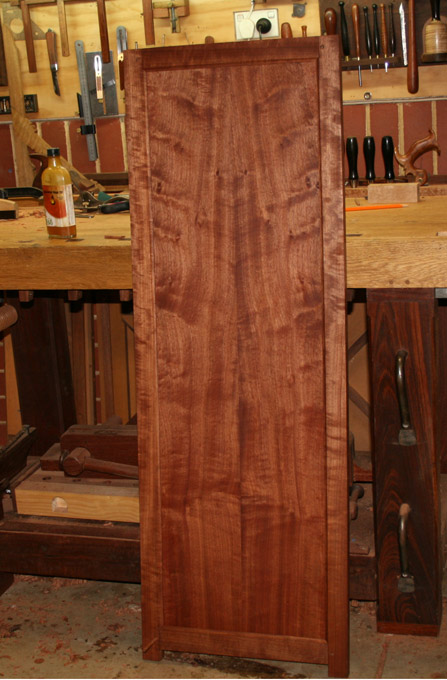
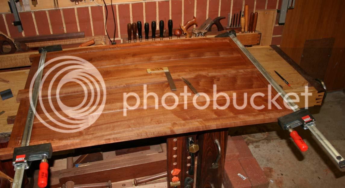
First of all I am very pleased - and relieved - to mention that the panels are back in one piece and together.

Then just a couple of comments about the failure and the hide glue ...

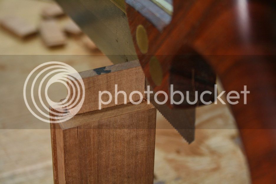
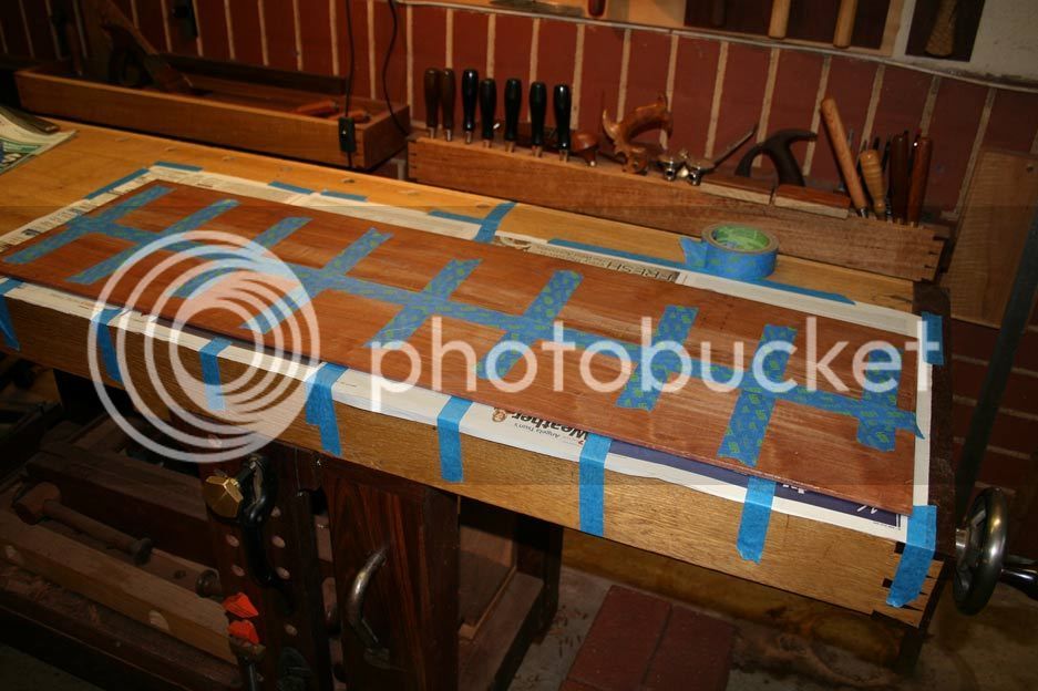
The reason for the failure was that the join was glue-starved. As simple as that. Well, almost.

The reason for the join being glue starved was not because I used too little glue, and not because of the type of glue, but because I over-tightened the clamps.

The over-tightening was due to the spring joint being too wide. What is a good- and what is a bad spring joint? Well, a good joint is one that may be closed with hand pressure, and a bad one is one that requires help to do so. In the case of the one panel, I got it right. In the case of the failed panel, clearly I did not. I could see light through the centre when I inspected the join, and immediately I knew this was the cause. Pulling the join together with a clamp just disguised the issue since all the tension was at the centre (where the join failed), and the force squeezed the glue out ...... no glue + tension = open up.

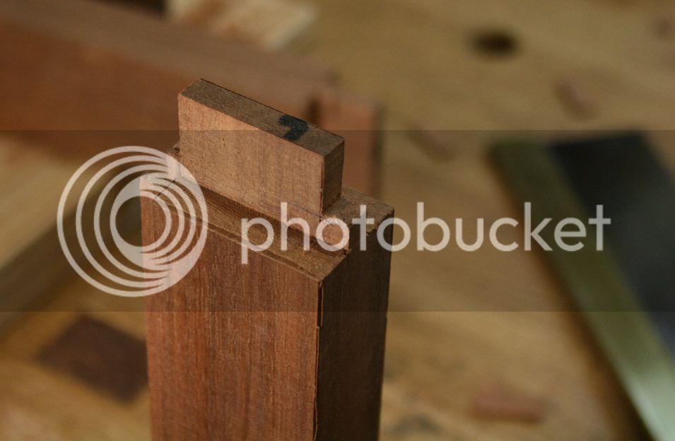
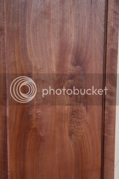
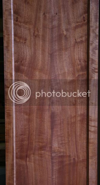
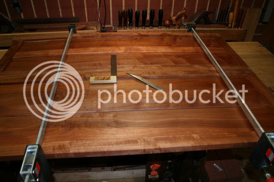
A second question is "why spring at all". Some like to do this and others argue that it is not necessary, that glue is tougher than wood. In my book, it is important to ensure that the ends of a panel contact each other. If there is any curvature to mating sides (and often this is difficult to see - which is the point), extra clamping at the ends creates two tension sections .. where as the spring joint only creates one tension point. But the spring must be almost imperceptible, as in the photo I posted.

A third issue is the choice of Titebond hide glue. Well hide glue rocks ... but Titebond? I have had a number of emails warning me about its use, that it is unreliable, etc. My experience with it is not long - about two years. In that time I cannot recall a failure. It needs to be pointed out that the mortice-and-tenon joints were solid. There was no failure there.

I must admit that I have avoided going to the trouble of preparing the stuff myself since I am lazy. The issue is that I get into the workshop on weekends only, and making up a fresh batch of glue each time, keeping it warm, etc .. well, it does not thrill me. Anyone have a way of circumventing this?

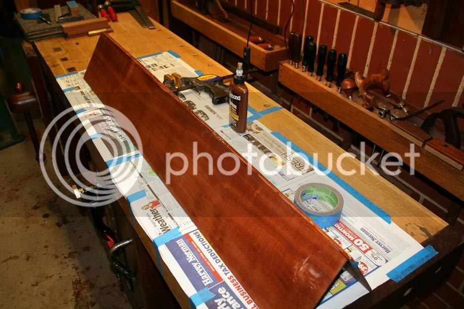
So back to the repair.

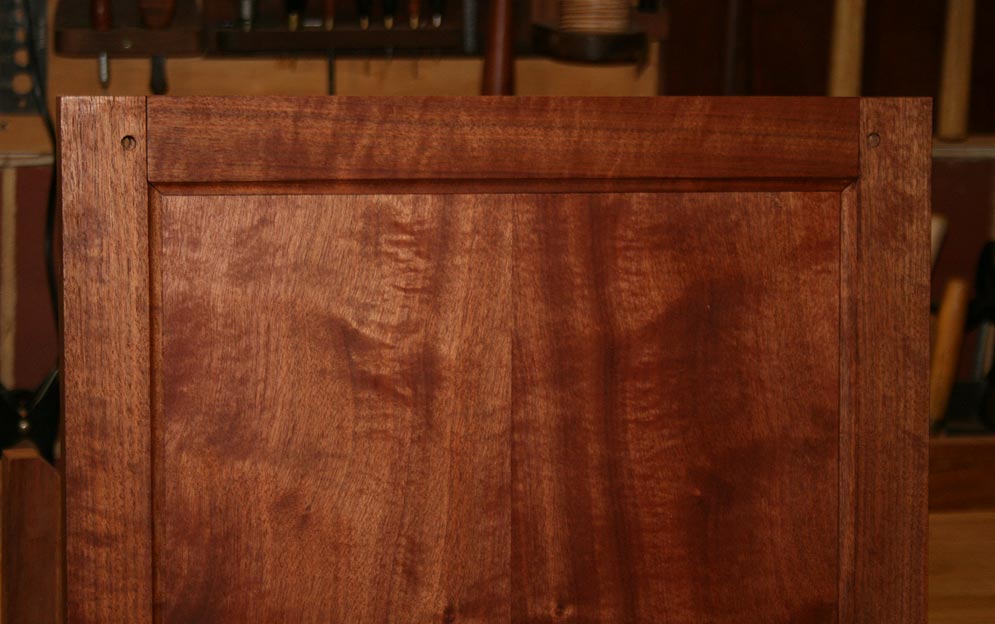
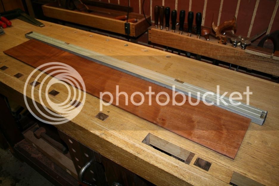
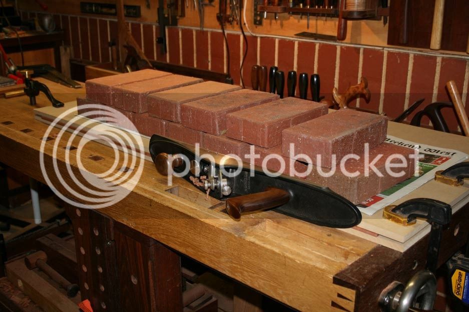
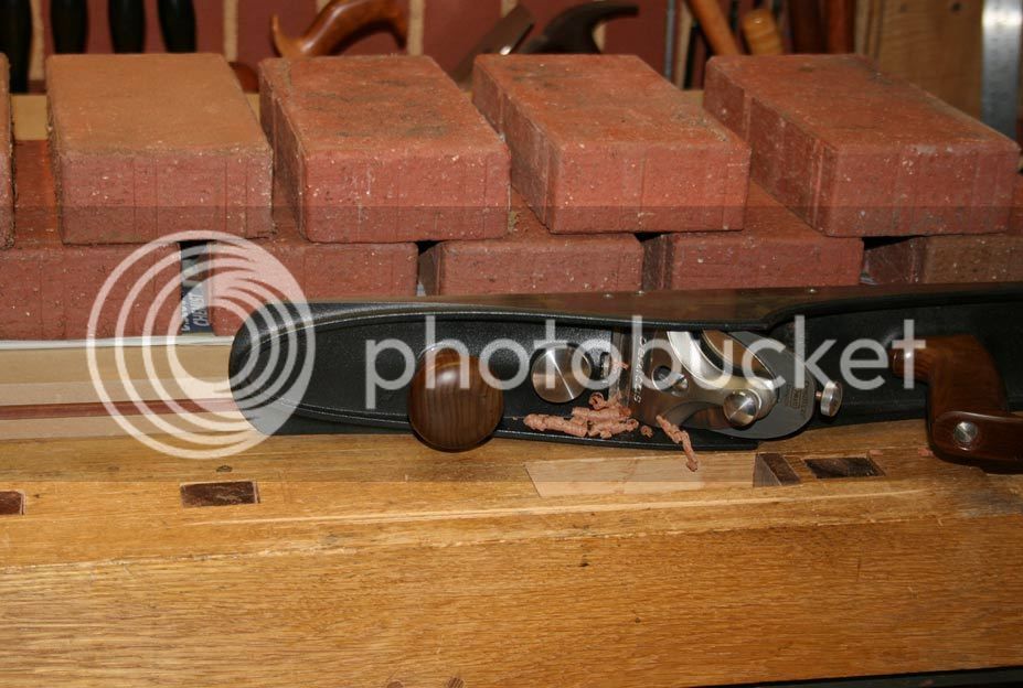
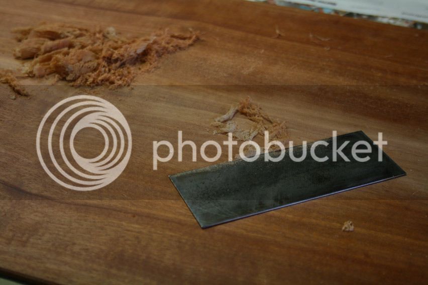
It the face needed a minimal amount of scraping to level the joint ...

Repair1_zpsknextyuc.jpg


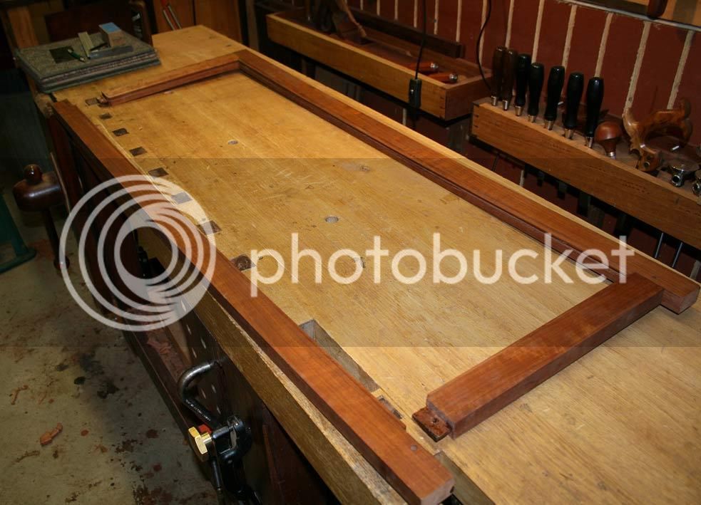
... before I called it good and re-glued and pinned the panel inside the frame.

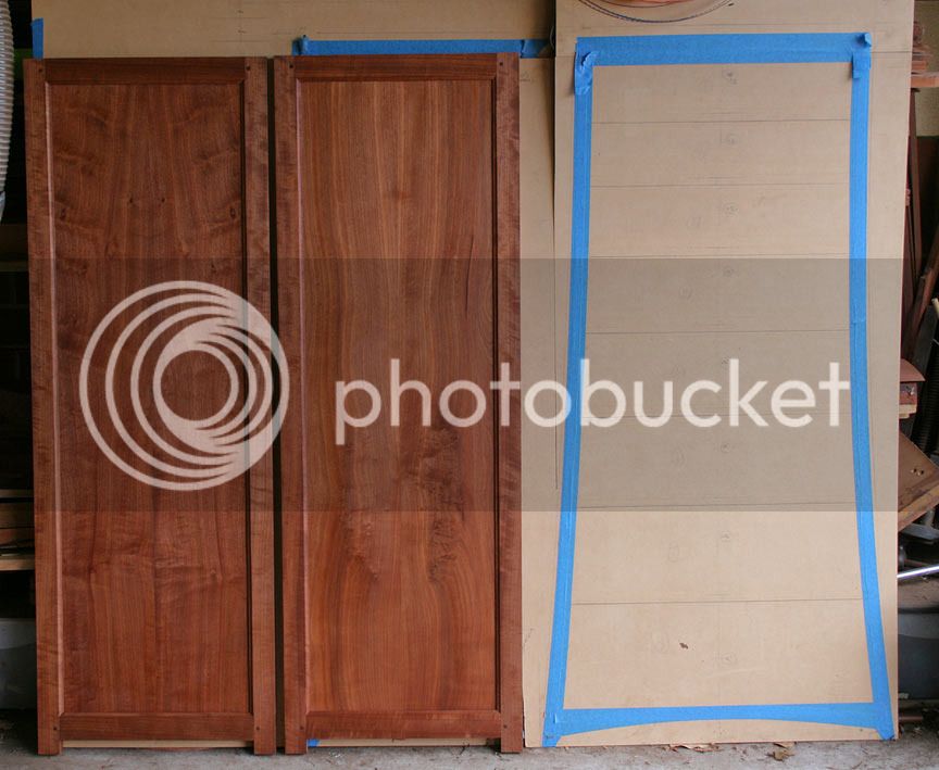
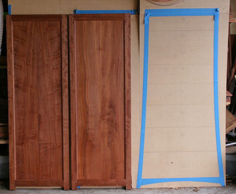
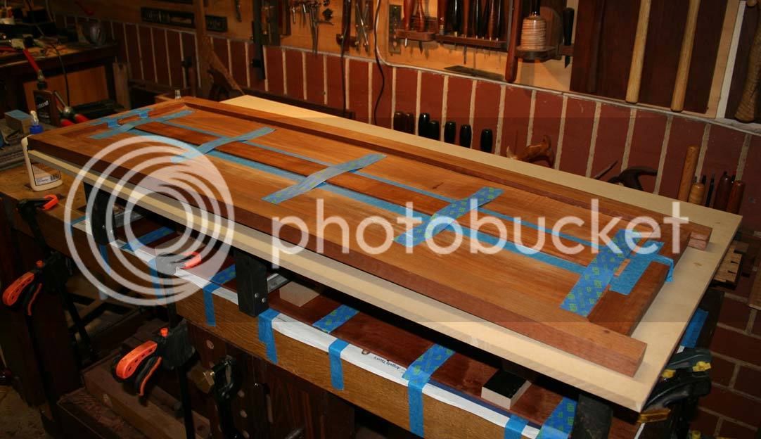
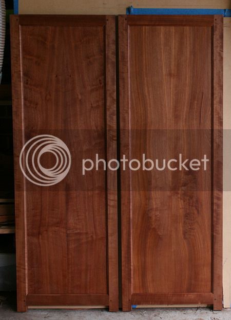
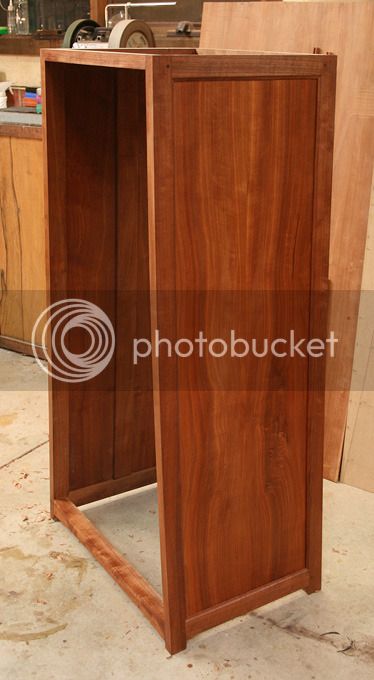
The repaired panel is on the left ...

100a_zpsdqocfkjw.jpg


102a_zpsk2owa6vt.jpg


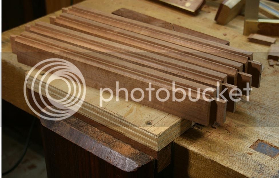
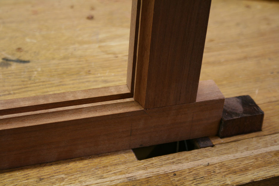
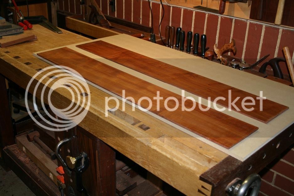
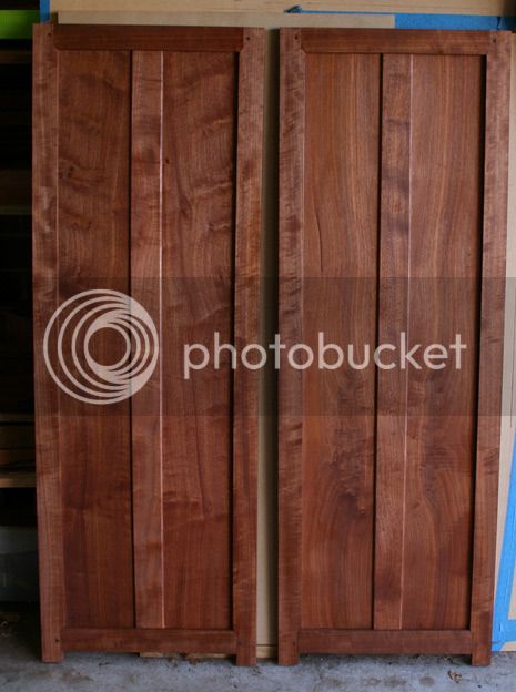
Reinforcing strips were added to the rear - I had planned to do this anyway to beef up the thin panels. They will not be seen (on the inside) but will offer a little more reliability ..

101a_zps1uyvh9qf.jpg


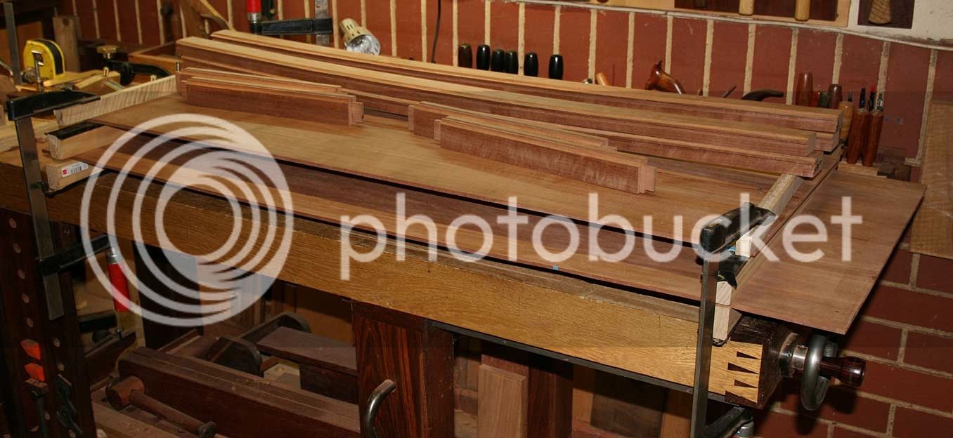
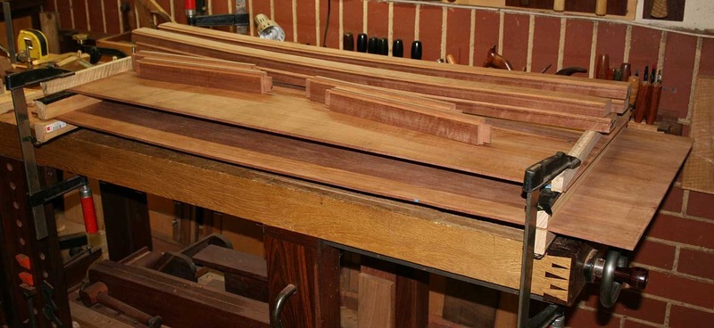
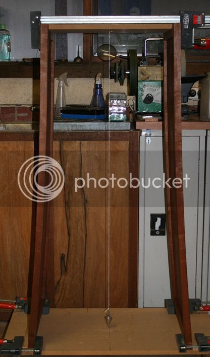
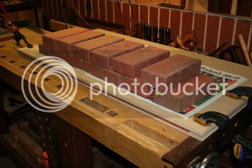
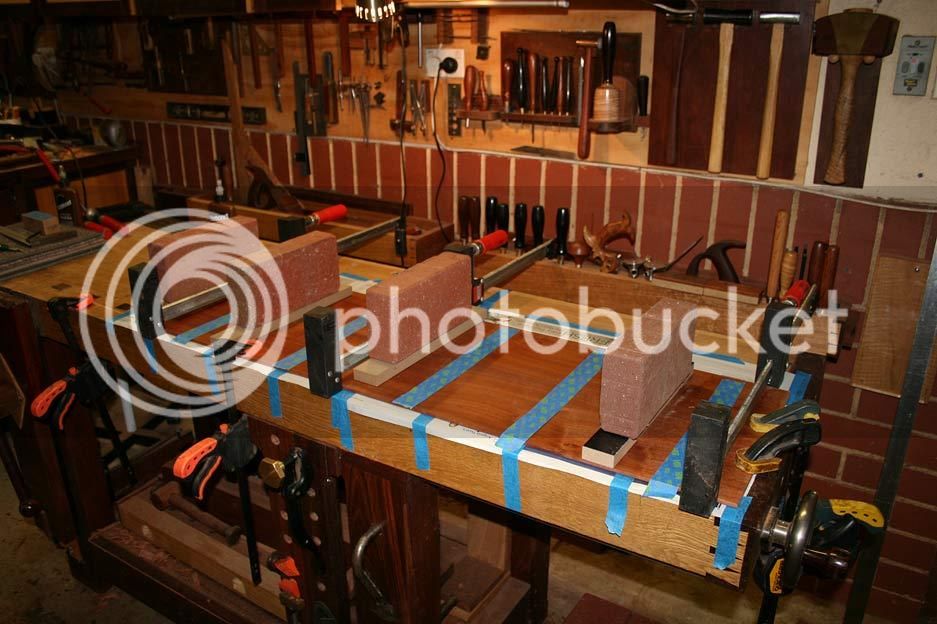
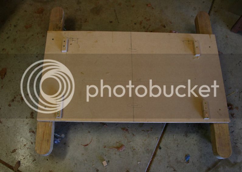
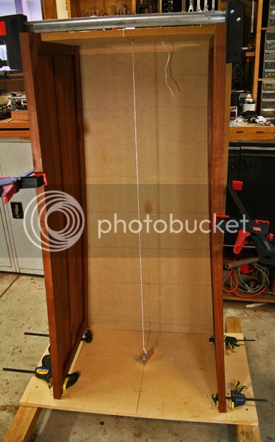
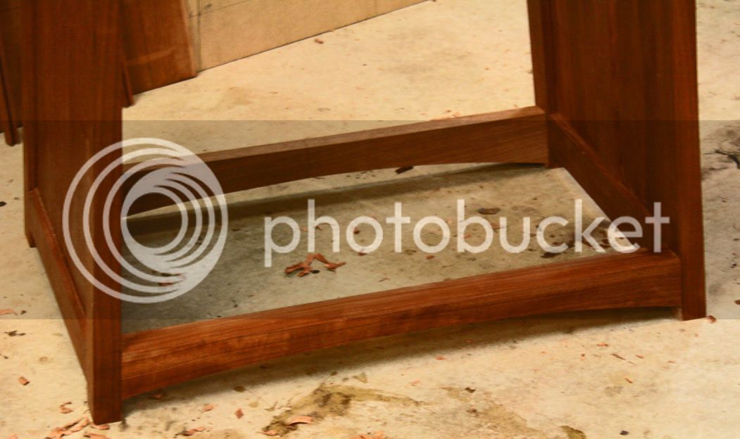
Some may be interested in the supports I built to aid accuracy in dimension and to keep everything square. The first was the base, which also will enable the chest to be moved around later ..

103a_zps9sljpygw.jpg


107a_zpskqyiuycn.jpg


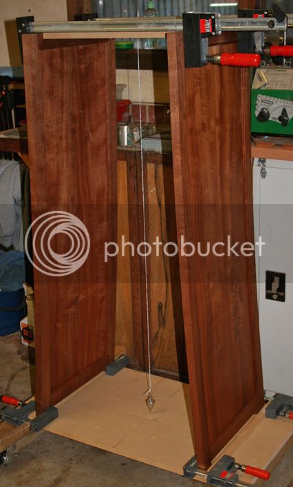
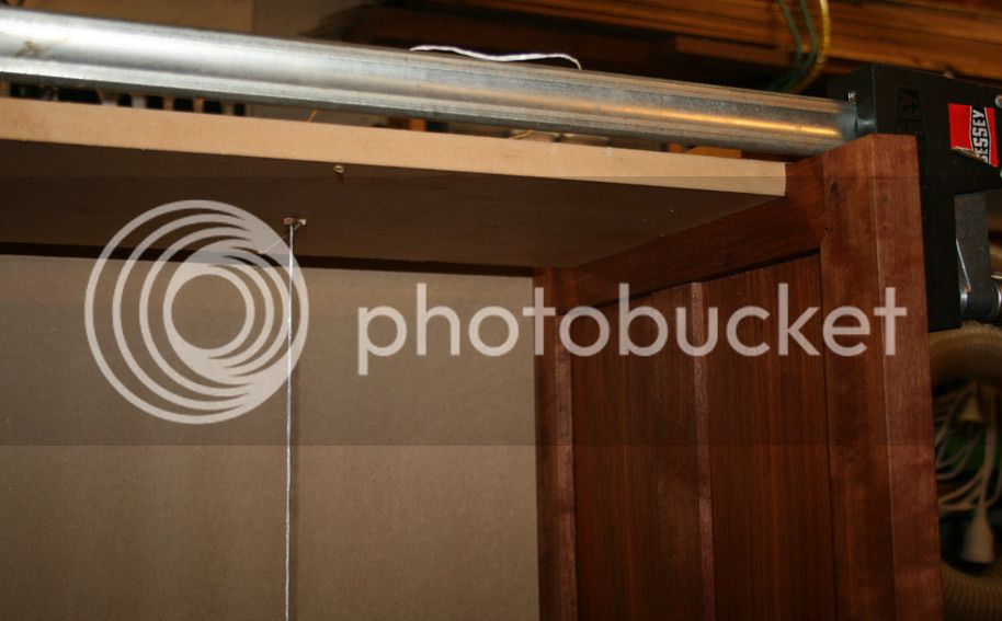
The other clamps across the top ..

104a_zps4l5c4zri.jpg


106a_zpst5hmkigg.jpg


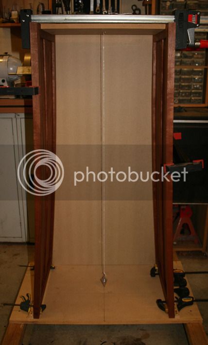
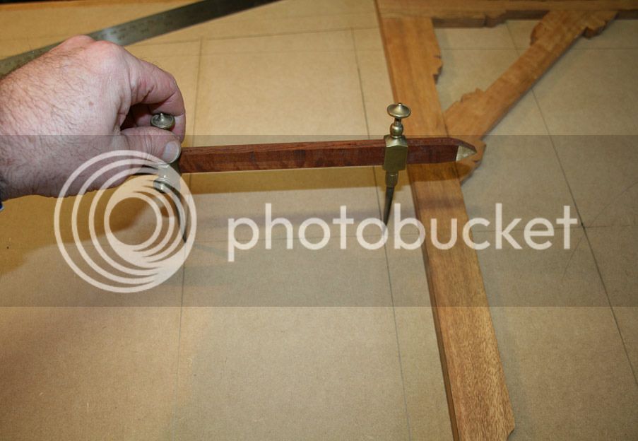
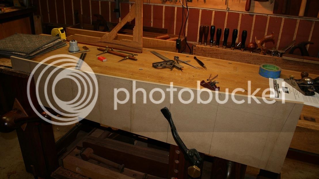
So now we are back to clamping all on the jigs, with an added section of MDF clamped to the rear. The plumb bob ensures that vertical and centre is created, and may be returned to at any time ...

105a_zpskebhfjhp.jpg


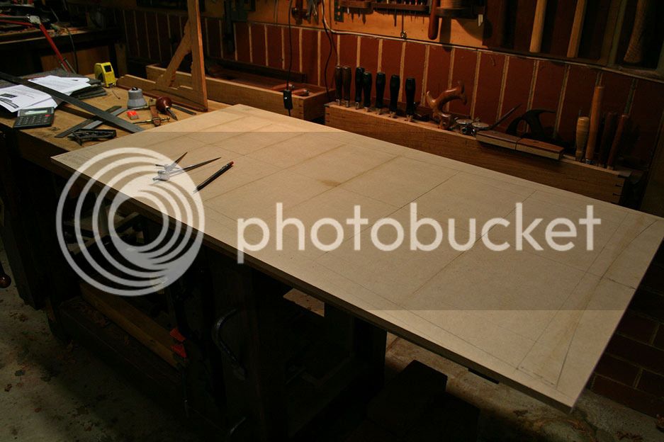
Once this is done, the inside perimeter can be traced onto the MDF. The MBF is moved to the bench, where the drawer dividers are drawn in. This is to act as a template.

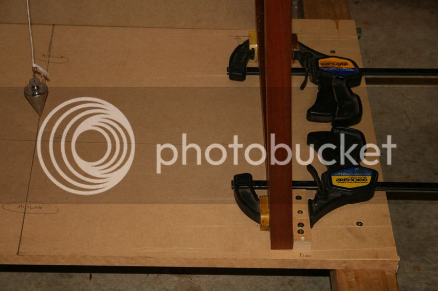
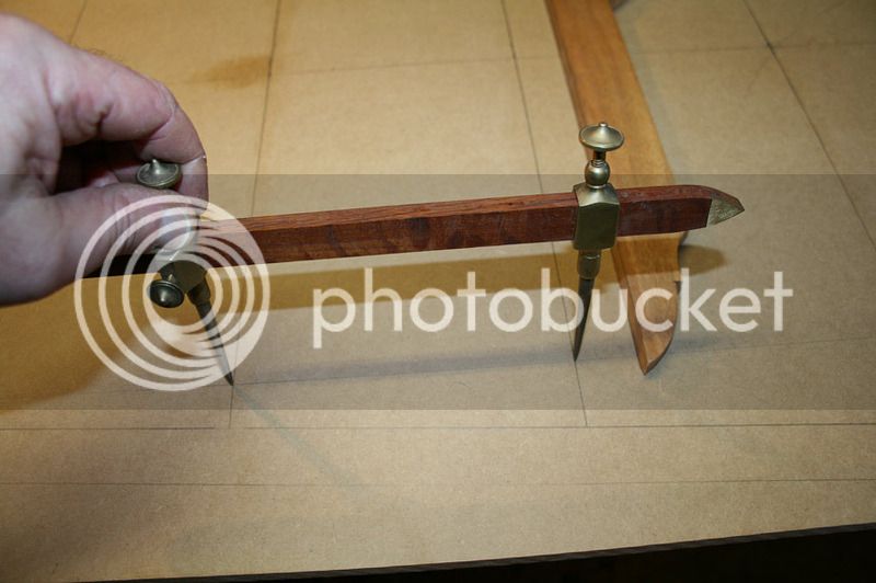
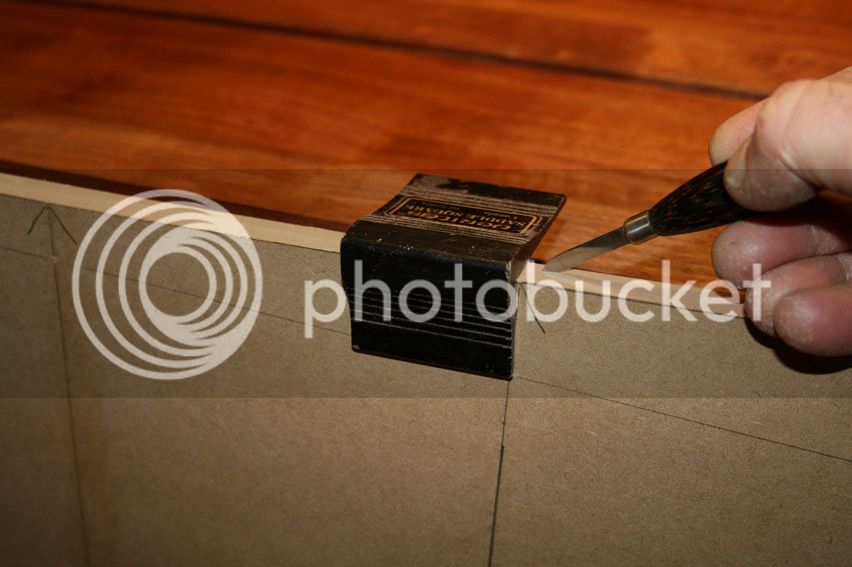
A line is drawn down the centre of the cabinet template, and the dimensions first marked on this centre line ...

108a_zpsqa6xegbj.jpg


They are then transferred to each side ..

109a_zpsvca5b5xf.jpg


110a_zpswxagzzoo.jpg


Here is the template back supporting the chest sides ...

112a_zpsd90mgb6b.jpg


I moved it to the other side and it was reassuring that there was about 1mm difference in the marked outline.

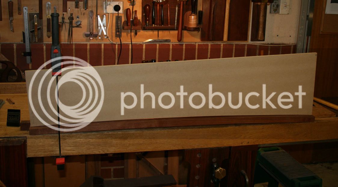
Now the intention was not to use these marks as the template, but rather to create a template from them. To do this the MDF outline was sawn down the centre, and then the curved side band sawn out, with a little cleaning up done with a small block plane.

113a_zpsgufh0dhd.jpg


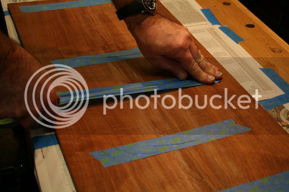
Measurements are marked both sides ..

114a_zpsrivqyv3o.jpg


... and then transferred to each side of one board (only) ..

115a_zpswvv9yybe.jpg


The panels are clamped together and the markings transferred from one board to the other ..

117a_zpshsyzogdx.jpg


Once one side is match, the boards are rotated to complete the other matching edges ...

116a_zpse1n9klw0.jpg


Now we can move on to marking out angled sliding dovetails and build the draw dividers.

Regards from Perth

Derek
 
The cabinet carcase is now complete and together as a dry fit.

68a_zpsinygb0dz.jpg


You cannot see the curve on the front elevation in this photo, but it is clearer in the documentation ..

66a_zps6xeeepmy.jpg


It had been my intention to post the carcase with completed draw blades – this would have been the next stage in any cabinet with straight sides. However it became increasingly apparent that, as a result of the many curves, this build is a tad more complicated, and I am have been left wondering whether I would ever get to be in a position to build the drawer blades as something else kept cropping up! It was a case of “I’d better to this before I get to that as it will not be possible later. And on and on ..

It is possible – and indeed I like to hear the opinion of others here – that the sliding dovetails for the drawer blades could be marked and formed from inside the completed carcase. I am now seriously considering this method. Indeed, I cannot see an alternative. The carcase could be dis-assembled and assembled repeatedly for work to be checked, carried out, and then checked again. However the latter will cause wear on the joinery, with resulting loss of tautness and accuracy.

Let's hear your thoughts on constructing the drawer blades. The front and rear are planned to be sliding dovetails (as has so much of this construction so far).

Here is the build in detail: http://www.inthewoodshop.com/Furniture/ ... lades.html

Regards from Perth

Derek
 
Back
Top