Bandsaw restoration advice.

UKworkshop.co.uk

Help Support UKworkshop.co.uk:

This site may earn a commission from merchant affiliate links, including eBay, Amazon, and others.
My previous comment maybe seemed a tad condescending . I forget people are not blessed with the facilities i have available .So if you have to knock the living daylights out of a bearing with a hammer, do it gently .Vice grips also serve a purpose if you havent got a full set of spanners ,and to be honest i suspect most folk dont own spanners to fit older english machinery .Some of which is whitworth /bs threads.Be careful taking them out because you will really have fun trying to replace them these days. Tread carefully
 
No problem from my perspective... :lol:

Here is a question. I went to buy a set of spanners of an old woman whos husband had recently died, leaving behind a massive workshop he used to make his own cars in. Fasinating place.

A lot of the spanners were marked W on the sizes. E.g. 3/4 W. The spanner was massive, way bigger than 3/4 inch.

What type of spanners were they?

Pete
 
PeterBassett":vm1y4kej said:
No problem from my perspective... :lol:

Here is a question. I went to buy a set of spanners of an old woman whos husband had recently died, leaving behind a massive workshop he used to make his own cars in. Fasinating place.

A lot of the spanners were marked W on the sizes. E.g. 3/4 W. The spanner was massive, way bigger than 3/4 inch.

What type of spanners were they?

Pete

My guess would be Whitworth - sure someone older than me will be along soon to explain the differences :D

Here's the wikipedia link: http://en.wikipedia.org/wiki/British_Standard_Whitworth
 
Yes whitworth can be rather hard to figure outThe thread sizes run one size bigger than BSF threads so some spanners will have dual markings ie 5/16w 1/4bsf are the same spanner (i might be wrong way round its been a while).Now if you find pre WW1 whitworth the head sizes change again ,they get bigger .I'm told they were reduced to save steel for the war effort .
unless you want a career fixing lots of british rolling stock (trains , DMUs etc) or classic tractors or motorcycles i strongly suggest you buy a good set of Bahco adjustable spanners . Having spent my apprenticeship carrying round a sackful of spanners of everyknown type metric af whitworth including BA (i even had to carry one guys kit that i swear didnt fit anybolts i or any other apprentice had ever come across "The renowned Mongolian Whitworth tool kit" that the silly ole fart wouldnt go anywhere without. Trust me on the Bahcos they never fail unless you are caught for space . Oh and dont forget , your old machinery if it has Caphead or sockethead (Allen) screws on it they will in all probability be Imperial as well
And i'm not that old .......... i think. If all this fascinates you on thread sizes go to an old book shop and get an copy of Kemps engineering .It will teach you allsorts of forgotton stuff ,youll get a tatty copy cheap Or even better for all you budding engineers get a Zeus book
http://www.amazon.co.uk/Precision-Refer ... 136&sr=1-1 its will give you drilling and tapping sizes for most relevant threads . i ve no affiliation btw . Mine cost me £1.20 as an apprentice and yes that wasnt in groats .....
 
.... and then there is BSP (British Standard Pipe) in all it's amazing glory.

Oddly, I think the BA sizes are in one sense "metric" in that the steps in size are tenths, but based on some weird inch measure.
 
BA threads are entirely based on the metric system.

Thread angle is 47.5 degrees and the dimensions are all determined by formulae using the BA number.

The only one I can remember of these is that the thread pitch is 0.9mm raised to the power of the BA number

eg 0BA pitch is 1mm, 2BA 0.81 and so on


Bob
 
More progress...

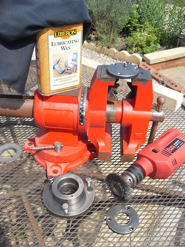
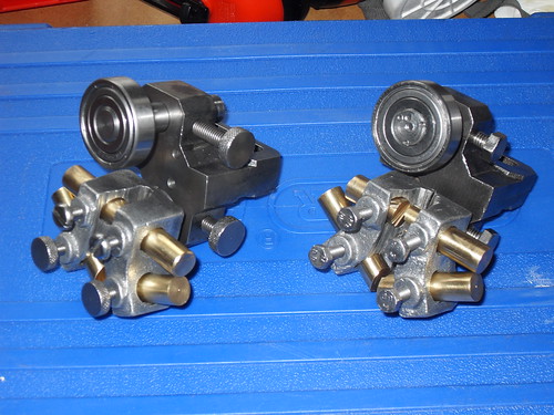
I decided to clean off the old green paint from the hub. I used an old drill with a wire wheel and spent 40 minutes getting all the paint off all off the hub components. This was my setup. I used my vice to hold each piece, cleaned them up and washed the grease off in the sink. Then gave them a good coat of lubricating wax to keep them relatively shiney.

4739006066_41407bbcd4.jpg


Once everything was coated I went down to the local car place and bought some new grease.

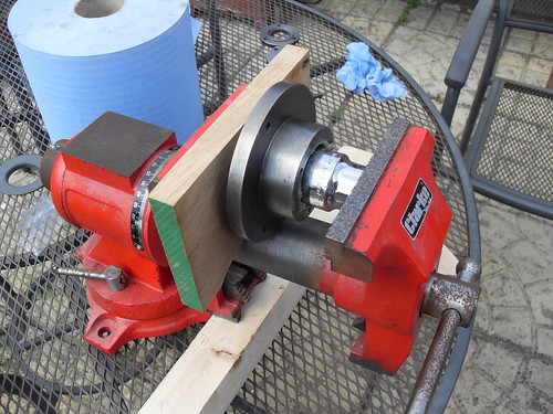
I gave the mating services in the hub a good coat and got the vice setup as shown. The bearings have been in the freezer since thursday! So, I got the setup ready, made sure the hub was ready and I had a correctly sized socket to act as a pushing block. Then I went to get the first bearing out of the freezer. I open the packet and quickly daube a load of grease all over it to keep the air away from it. Then put everything into the vice and press it in. It worked perfectly first time, a very nice controlled press. 30 seconds and it was done.

4738371871_659d2cb422.jpg


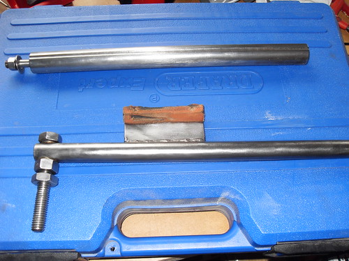
Next I placed the spacer into the hub, from the other side, and held it in place with a load of grease all around.

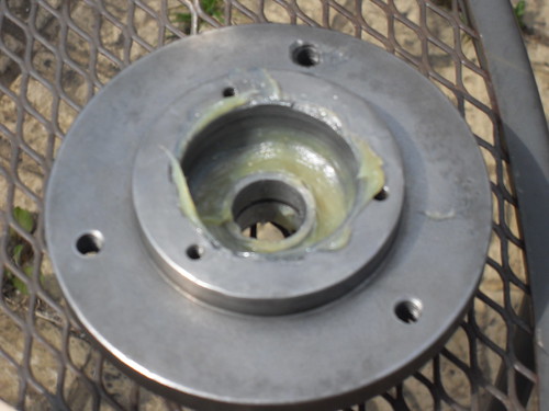
You can see the spacer here being held in the correct position by the grease.
4739001698_023b9e5fbc.jpg


Then I put the second bearing in. This was slightly more difficult than the first one. I used the same procedure but it just wouldn't begin to seat evenly. I ended up tapping the bearing in with a small hammer for the first 1-2mm. This worked fine and I only used the hammer until the bearing was on it's way. Then it was pressed in with the vice as per the first one.

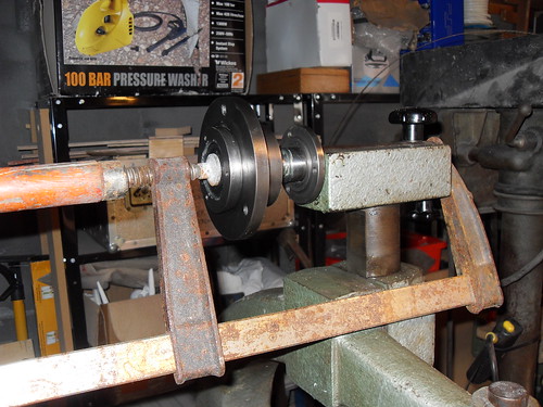
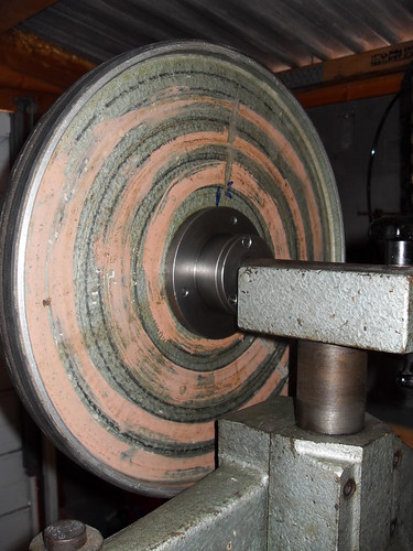
Once the hub was together I had to press it onto the shaft. I cleaned up the shaft and gave it a good coat of grease. I offered up the hub and helpfully it would go on about 2 mm just from hand pressure.

Once it was started I could get my "bearing presser" into place. This you will notice is just an old rusty clamp. I was going to use one of my largest record G-Clamps but its foot was too large for the bearing and the socket was too large to fit in the clamp. So I used this instead. The foot is the perfect size for the inner race.
4738999676_1d94b5e815.jpg


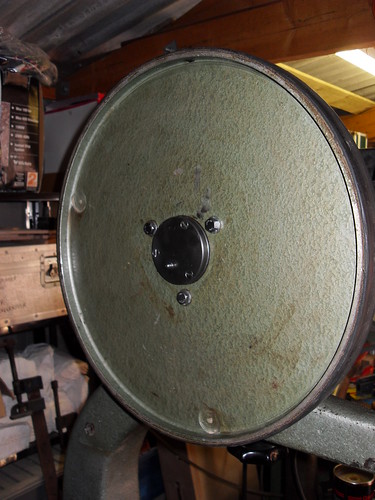
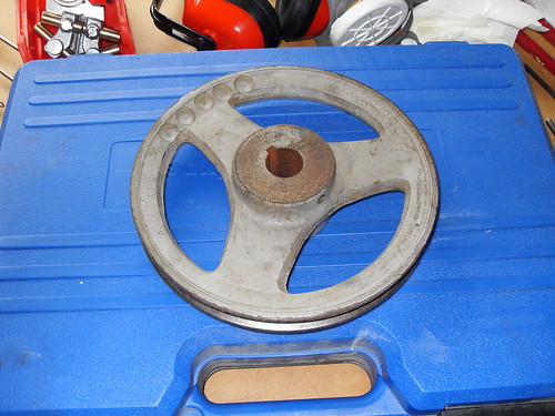
Once the hub was on it remounted the wheel and here it is in all it's glory!

4738365567_4675067df3.jpg

4738363637_d987755eed.jpg


It *still* doesn't spin for as long as the bottom wheel but it is completely silent! I can't hear it at all. Lovely.

So, all in all it was pretty easy to do and I like the bare metal finish. I'll have to keep an eye on it and it'll nead a coat of wax every now and then but it's done!

On to the next issue. The rattly motor mount!

Thanks all

Pete
 
Congratulations Pete - I hope I'm right in remembering now that you started off as a pretty non-confident mechanical engineer; you've passed your exam with flying colours ! Well done.

Two possible reasons for the new wheel not running on as long - the bottom wheel may well be heavier as it will have the drive pulley on it, but more likely is that the new bearings will have to bed in a little and find their way round all that grease you've given them.

Rob
 
More progress.

I've removed, disassembled ,degreased, paint stripped and wire brushed all components of the blade guides. Everything has been given a coat of lubricating wax to keep it shiney. I bought and fitted some new bearings because the old ones were shot. I'm not afraid of bearings anymore!

Here are the finished items. (Left = Upper, because it has more original fittings. Right = lower, because all the nice knurled knobs have been replaced with bolts.)
4778953585_be4f254c86.jpg


You'll notice that the aluminium blocks that hold the brass blade guides have some fairly major grooves cut in them. They are still solid but god knows what the previous owner thought he was doing there...I'll be taking a file to the brass rods soon to get the end profile I want. They are all chewed up at the moment. Any suggestions?

I've also been cleaning up some other parts. Here is the mounting bar for the upper blade guide and the brake for the saw. It is pulled up and contacts the main pulley. Not sure about it really.
4778952675_fa34906553.jpg


Finally a question. Here is the main pulley. It mounts to the shaft that the bottom wheel is also mounted to.
4779584476_7bf24cb7d8.jpg


It *can't* be the original item, the fit to the shaft is sloppy and when you tighten the set screw the sloppiness translates into it not being concentric with the shaft. The edge of the pulley wobbles in and out by a 16th and about an 8th vertically. Obviously the vbelt doesn't like getting tighter and looser with every revolution. This also causes the motor to move up and down with every revolution because the motor is mounted such that it's own weight is used to tighten the belt.

Not a good state of affairs.

So, I've done some researching and I figure I need one of these.
http://www.bearingboys.co.uk/SPA200_1_V_Pulley-4530-p
and one of these
http://www.bearingboys.co.uk/2012-1_Taperlock_Bush-2373-p

The shaft they need to fit to is 980 thou and I *think* the taper lock bush I have picked there is to fit a shaft of 1 inch.

My question is, is this right? :lol: Do taper lock bushes need a particular clearance?

Thanks again, Pete
 
Not sure on the spec for taper lock bushes but I reckon they will pull down fairly well but with some eccentricity but a lot less than you have at them moment.

Best solution would be to get someone to turn down the shaft end and modify the key for a 25mm bush.

HTH

Bob

Edit: Sorry that is bollo x 25mm = 0.984

I think you just need a 25mm bush - even easier!!

1st rule of processing a measurement is convert it to metric/imperial and see if it makes more sense. Also convert part inches to 64ths for further enlightenment as to the intended dimensions.
 
9fingers said:
1st rule of processing a measurement is convert it to metric/imperial and see if it makes more sense. Also convert part inches to 64ths for further enlightenment as to the intended dimensions.

That's an interesting tip, Bob, which I think I have been doing subconsciously but I hadn't thought about the 1/64's. I did see something (can't remember what now !) advertised on a US website recently that had a key dimension that was something like 39/64". Seems a total anachronism in this day and age.

Rob
 
OldWood":3qw9cua9 said:
I did see something (can't remember what now !) advertised on a US website recently that had a key dimension that was something like 39/64". Seems a total anachronism in this day and age.

Rob

I live with both systems. I still like imperial for a lot of my work.

Much easier for say centring an object - make the measurement and double the denominator. Also the magnitude of the numbers are easier to handle for quick (ish) mental arithmetic. eg centre 42 5/8ths = 21 5/16ths
With the metric system you are quickly into 4 digits when making even modest things.

If you want some fun - try working in Mile Ton Fortnights.
This stemmed from when I was at school and CGS, MKS and FPS were all in use and our physics homework questions were prefaced with:-
"You may work in any units of your choosing but be consistent throughout the answer"
So we smart4rses did just that and worked each question in different unit systems.
Very silly but we were then
Bob
 
Bob - we must be much of an age; don't remember having the opportunity to do naughty things like that ! :twisted:

Rob
 
Hi.

Thanks for that bob.

I've been looking at the blade speed, these are the numbers I have.

Motor Pulley Diameter : 51.2mm
Main Pulley Diameter : 210mm
Wheel Diameter : 400mm
Motor Speed : 2850rpm

From that I worked out that using the existing main pulley I get 871m/min which is probably about right. Do you agree? Would anyone recommend changing this speed?

I have also double checked the shaft diameter. It varies between 24.95mm and 25.08mm

Sounds like you are right about using the 25mm bush.

Pete
 
The new pulley and taper lock bush have arrived! I've offered up the bush and it fits perfectly. Little to no slop even before it's tightened up.

Some more pictures to come tonight!

Pete
 
Back
Top