You are using an out of date browser. It may not display this or other websites correctly.
You should upgrade or use an alternative browser.
You should upgrade or use an alternative browser.
Another New Yankee Style Router Table
- Thread starter The Bear
- Start date


Help Support UKworkshop.co.uk:
This site may earn a commission from merchant affiliate
links, including eBay, Amazon, and others.
I'm still building this but progress has slowed significantly due to holidays, work, other projects and watching too much olympics. I am still trying to do bits here and there though.
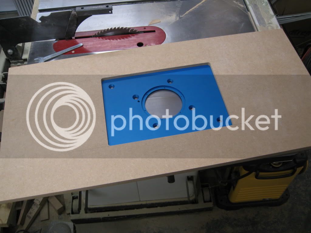
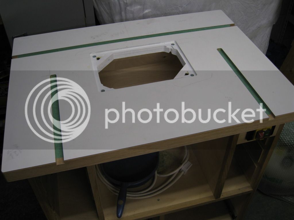
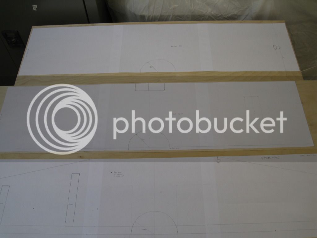
I've cut the hole for the plate as follows. The plate is from Rockler and for the big Triton.
First, the plate is placed on a piece of MDF and smaller pieces stuck around it using double sided tape
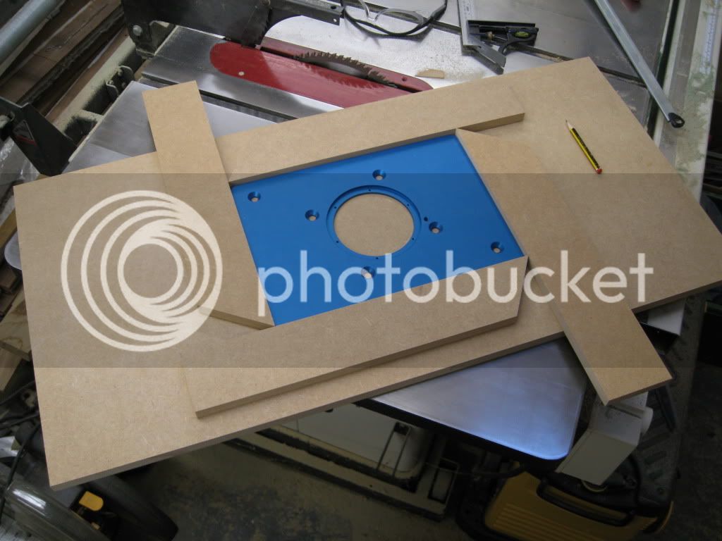
I then used a bearing guided flush trimmer to cut the template through
Guides removed to give the finished templates.
Mark
I've cut the hole for the plate as follows. The plate is from Rockler and for the big Triton.
First, the plate is placed on a piece of MDF and smaller pieces stuck around it using double sided tape
I then used a bearing guided flush trimmer to cut the template through
Guides removed to give the finished templates.
Mark
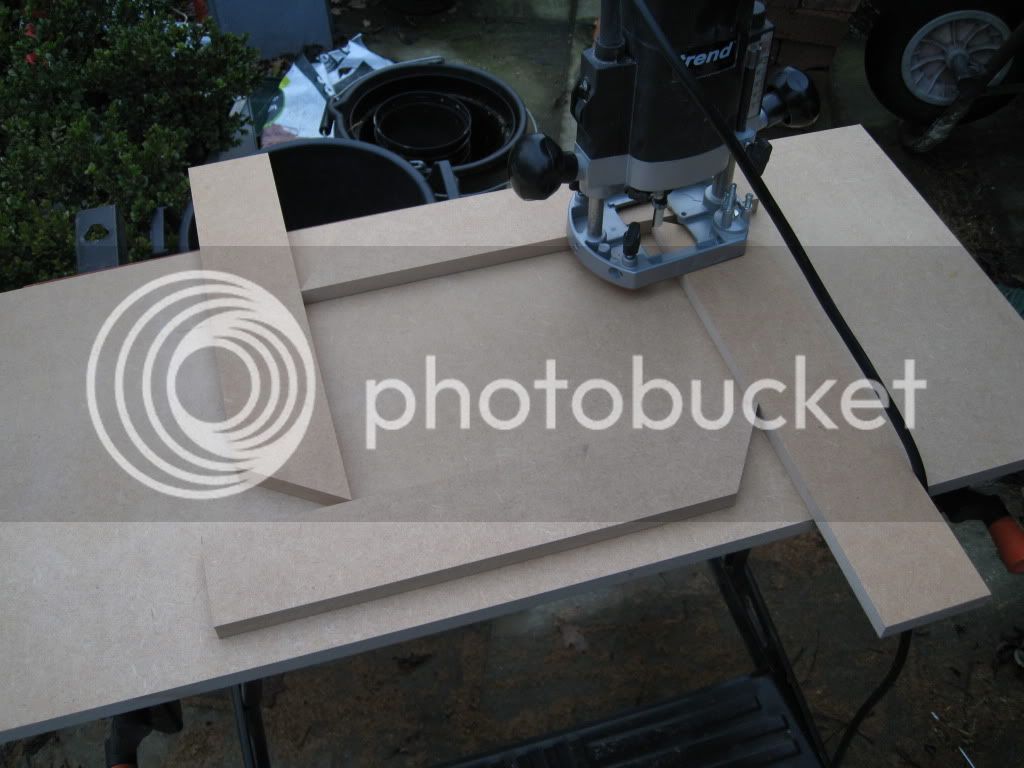
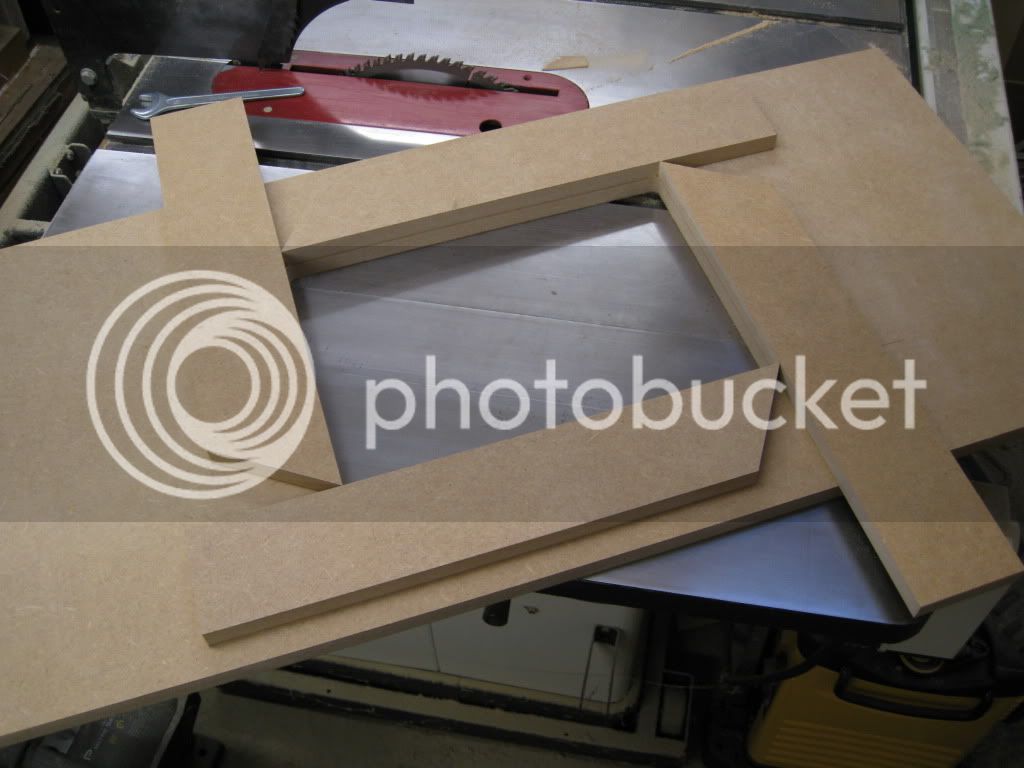
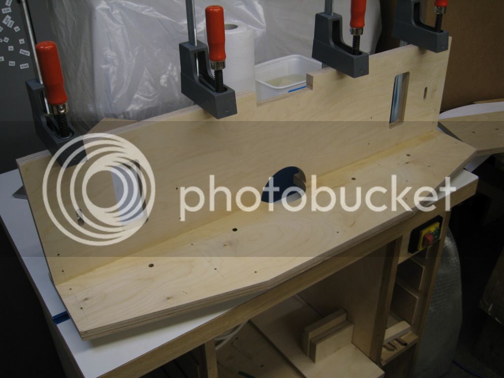
Its then just a case of clampingit to the top and router the hole
I then realised I had routed too much of the corners away and had to stick a bit back on, doh
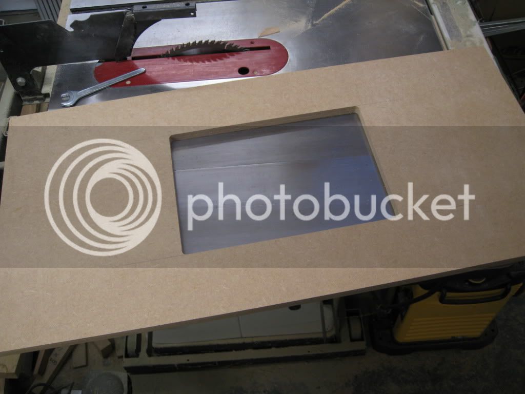
Bare MDF sealed with paint
i have fogotten to take a photo of the plate in the top
Mark
I then realised I had routed too much of the corners away and had to stick a bit back on, doh
Bare MDF sealed with paint
i have fogotten to take a photo of the plate in the top
Mark
Eric The Viking
Established Member
- Joined
- 19 Jan 2010
- Messages
- 6,599
- Reaction score
- 74
I'm making notes
Thanks for taking the trouble to document this - it's really useful, and it's looking good too.
E.
Thanks for taking the trouble to document this - it's really useful, and it's looking good too.
E.
The worlds slowest router table build has been continuing.
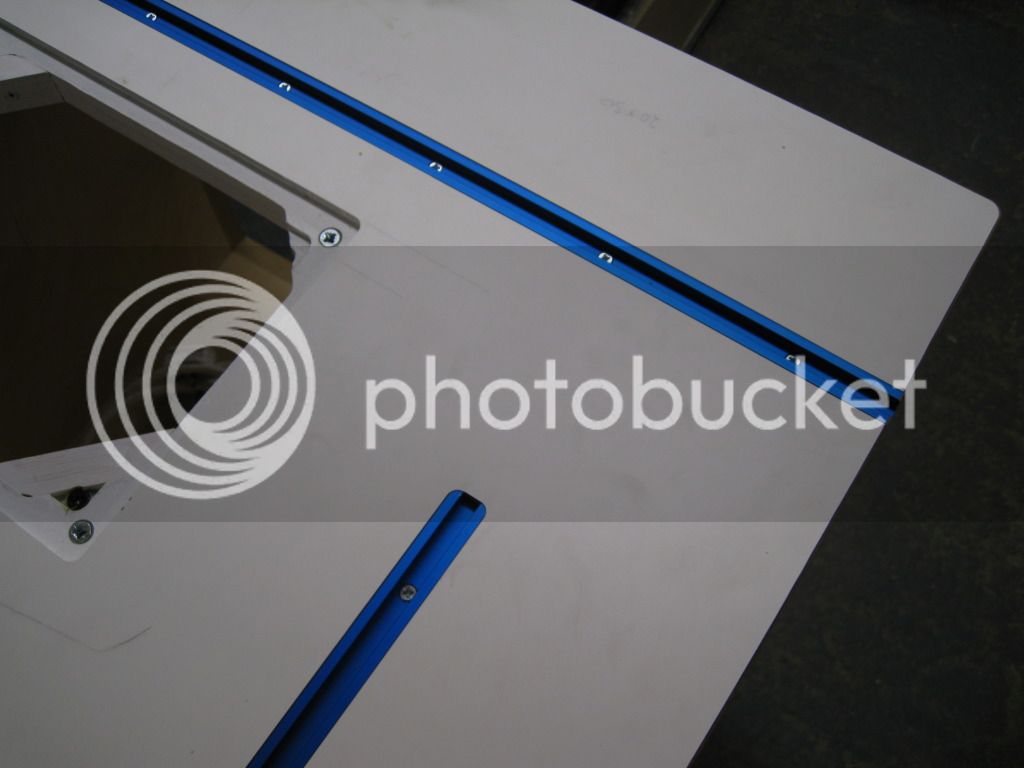
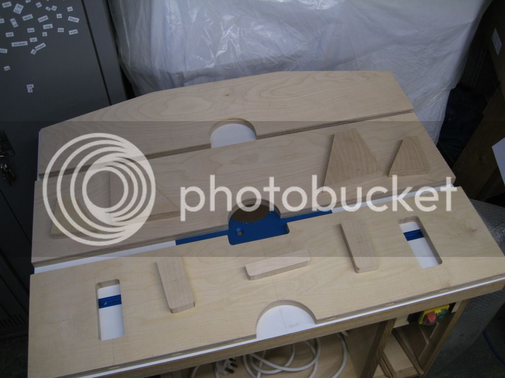
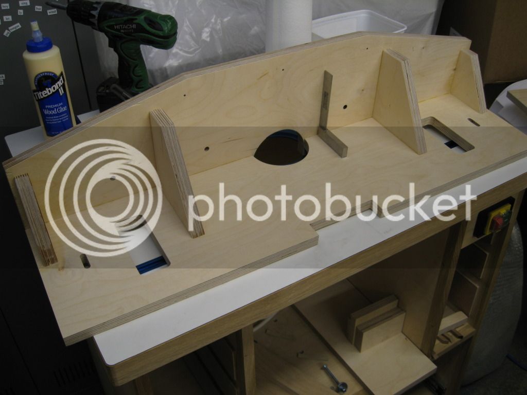
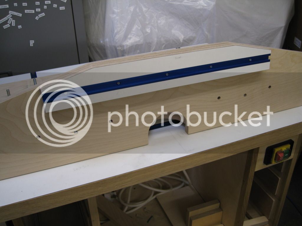
Next job was to continue to work on the top, router out for the t tracks, using a couple of guides. I had made the guides previously and they are slightly too short for the top, so i just routed a bit then slid the along and it turned out fine.
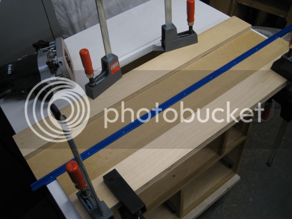
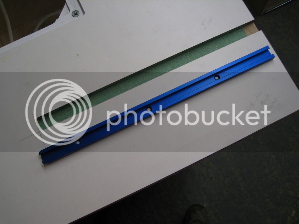
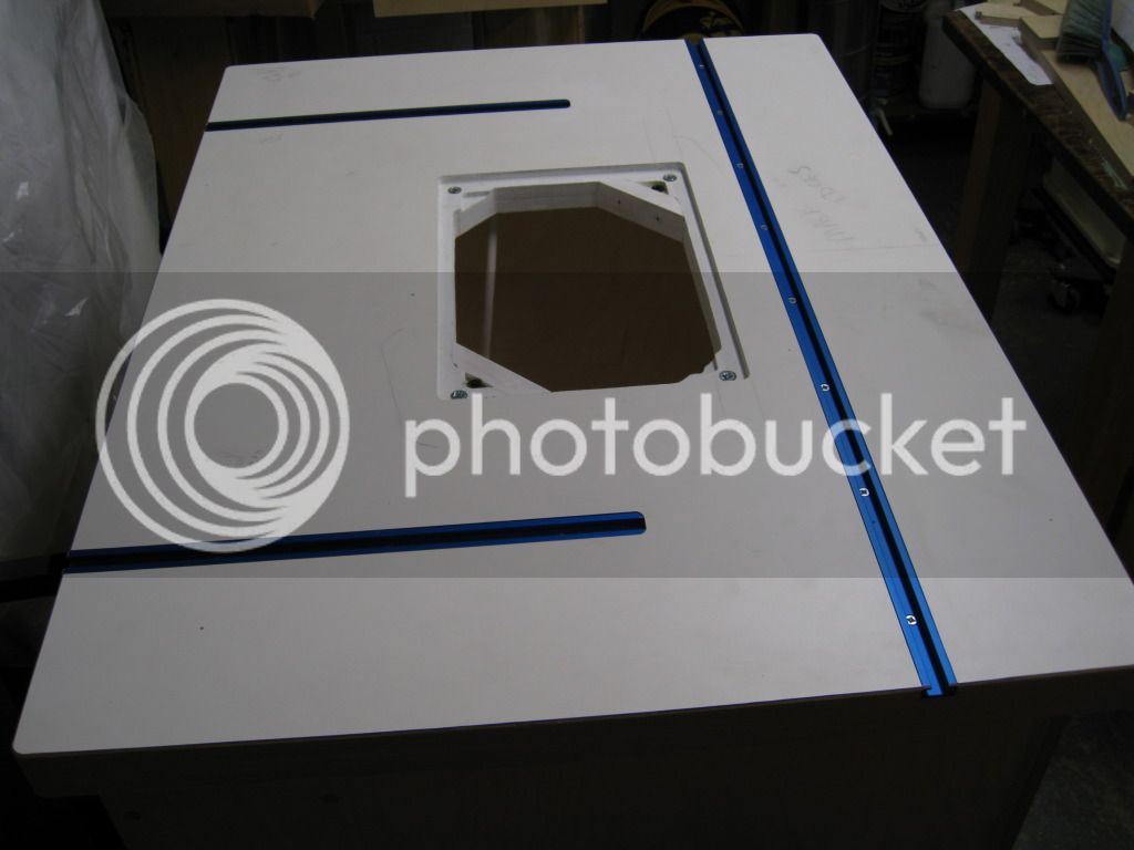
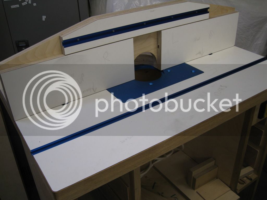
You will see there is one track along the long side for clamping down featherboards etc. Then there are 2 stopped tracks which the fence will clamp down to.
Then just cutting the tracks to length, rounding off the ends of the short tracks with a file and fixing in
Mark
Next job was to continue to work on the top, router out for the t tracks, using a couple of guides. I had made the guides previously and they are slightly too short for the top, so i just routed a bit then slid the along and it turned out fine.
You will see there is one track along the long side for clamping down featherboards etc. Then there are 2 stopped tracks which the fence will clamp down to.
Then just cutting the tracks to length, rounding off the ends of the short tracks with a file and fixing in
Mark
Couple of other bits and bobs done
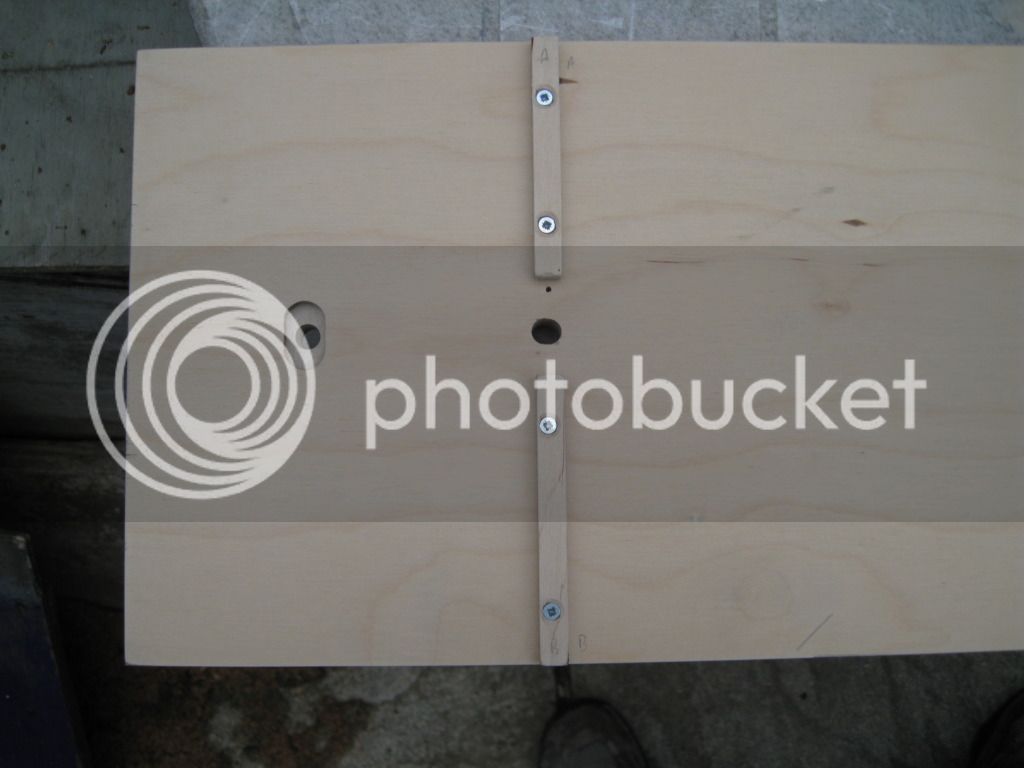
Blocks screwed to the underside of the top to keep it in place
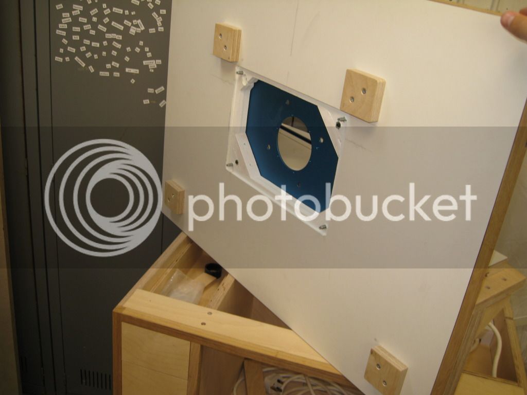
This picture shows my original attempt at routing the hole for the plate, complete cock up.
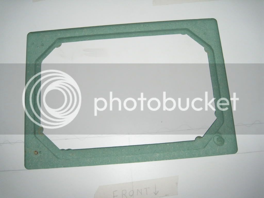
You might have spotted that behind the section in the base where the router hangs and behind the small drawers is a space. This is where my extraction piping will go. I've got an idea on how the piping will work but still not completely sorted yet. Anyway the back propper needs to go on over this space. It will have a removable panel to get at the pipes easily and also change it about if its not working very well.
Panel jigsawed out and then trimmed straight with the router and guide rail
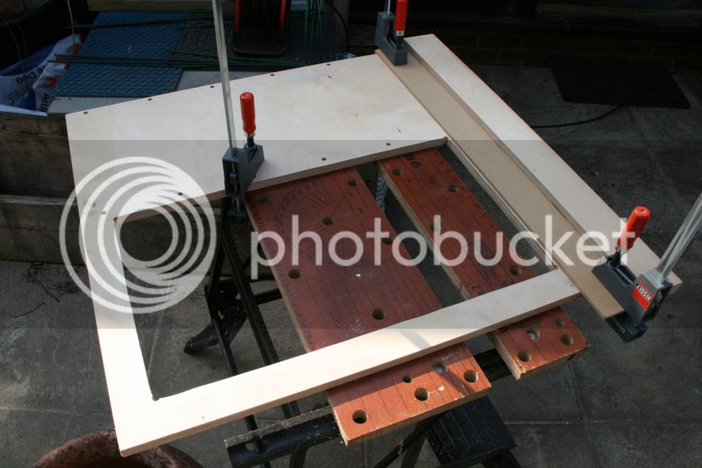
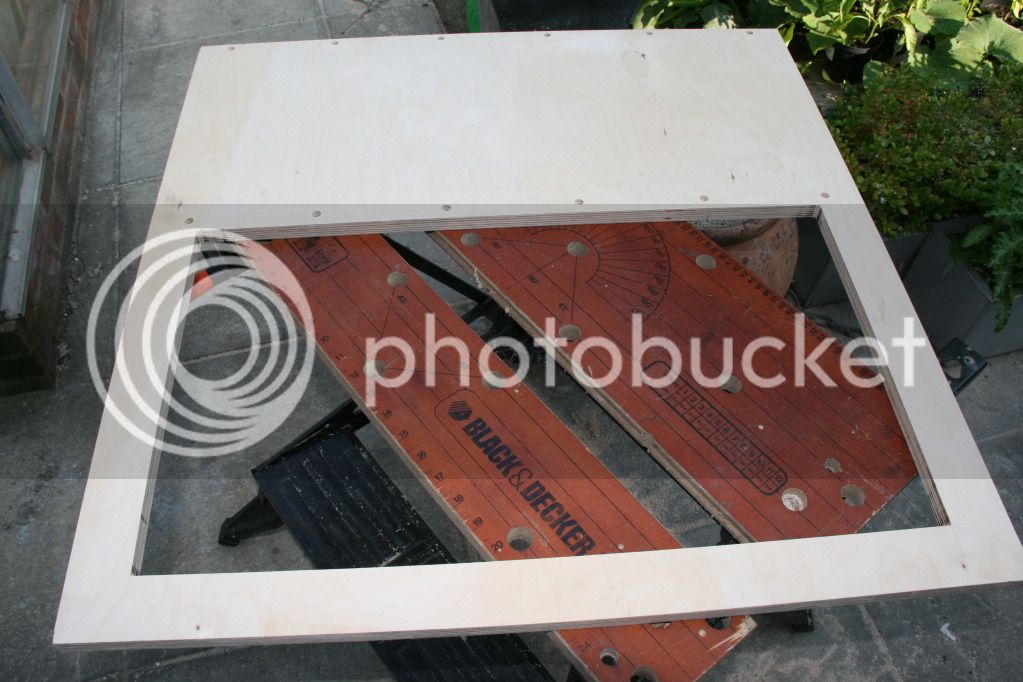
Corners chiseled out square
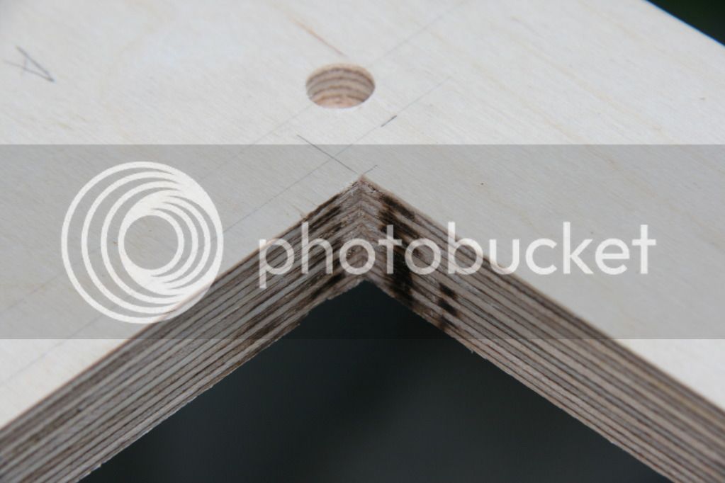
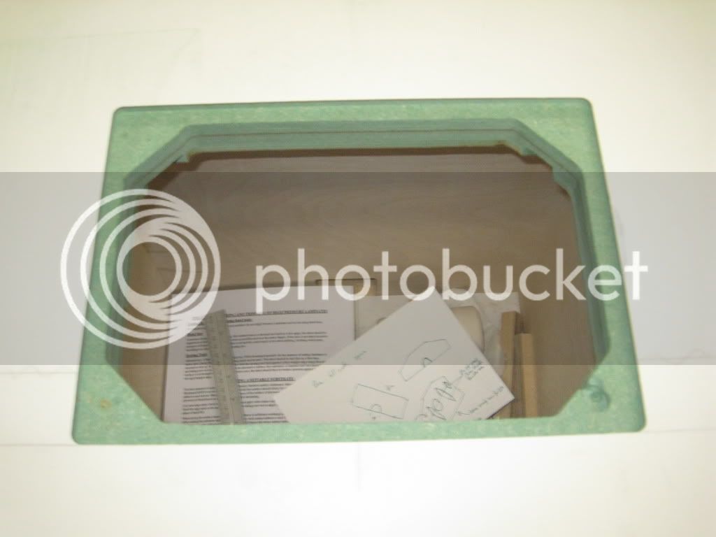
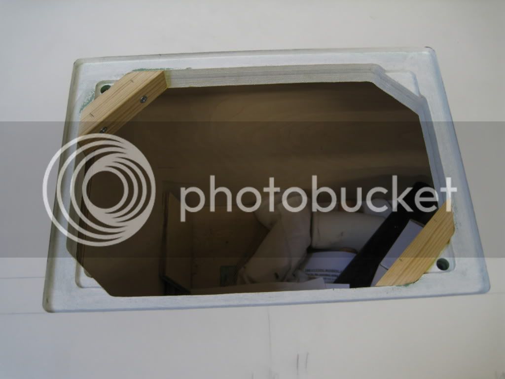
The inner edge had a thin strip of oak stuck on then it was screwed to the back of the cabinet. Sorry the photo is a bit close up, I'll take one from further back another time. You can also see a triangle of wood stuck on the inside across the corner which will support the back panel.
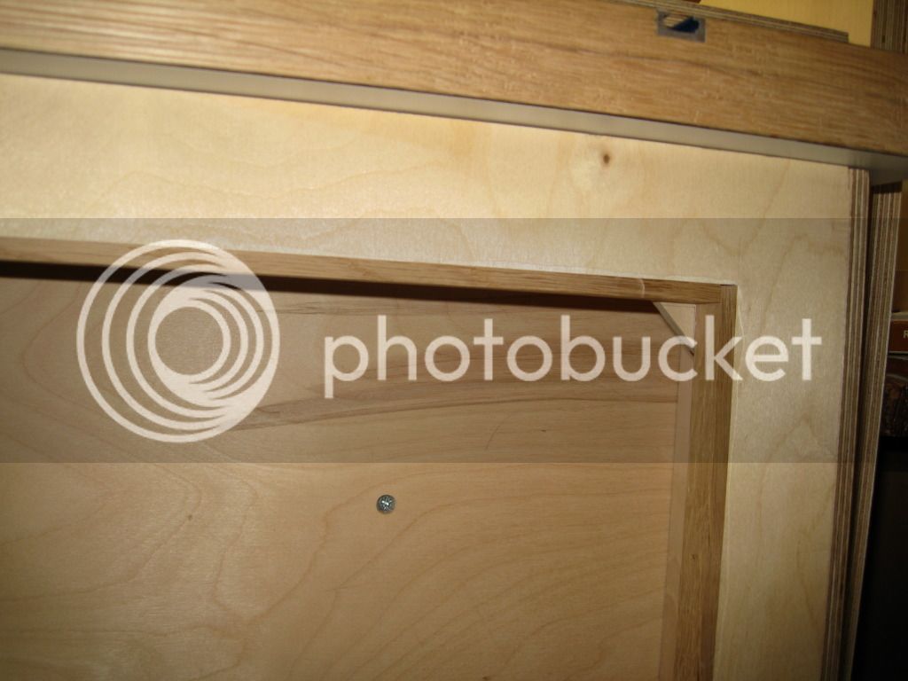
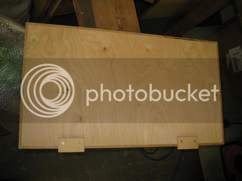
The insert I jigsawed out was then squared on the table saw
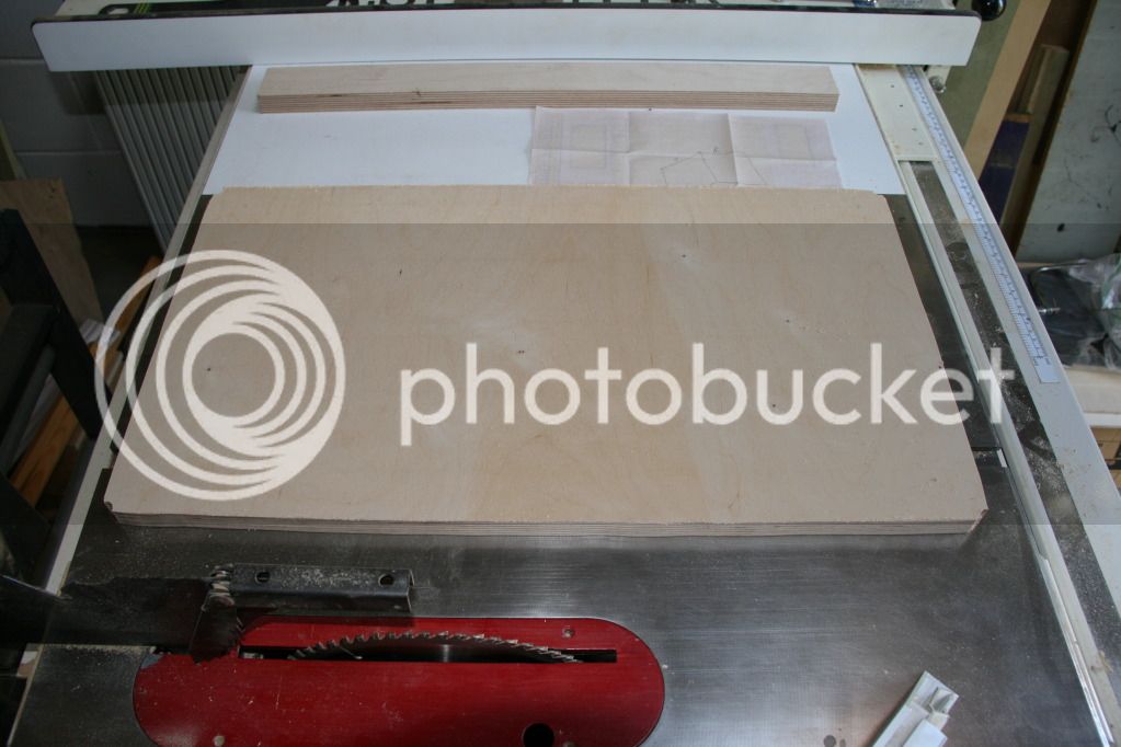
The insert also then had a thin edge of oak applied and a couple of blocks screwed on. These will sit inside the back frame to hold it in place and I'll just screw a toggle to th etop to hold the whole thing in place
Mark
Blocks screwed to the underside of the top to keep it in place
This picture shows my original attempt at routing the hole for the plate, complete cock up.
You might have spotted that behind the section in the base where the router hangs and behind the small drawers is a space. This is where my extraction piping will go. I've got an idea on how the piping will work but still not completely sorted yet. Anyway the back propper needs to go on over this space. It will have a removable panel to get at the pipes easily and also change it about if its not working very well.
Panel jigsawed out and then trimmed straight with the router and guide rail
Corners chiseled out square
The inner edge had a thin strip of oak stuck on then it was screwed to the back of the cabinet. Sorry the photo is a bit close up, I'll take one from further back another time. You can also see a triangle of wood stuck on the inside across the corner which will support the back panel.
The insert I jigsawed out was then squared on the table saw
The insert also then had a thin edge of oak applied and a couple of blocks screwed on. These will sit inside the back frame to hold it in place and I'll just screw a toggle to th etop to hold the whole thing in place
Mark
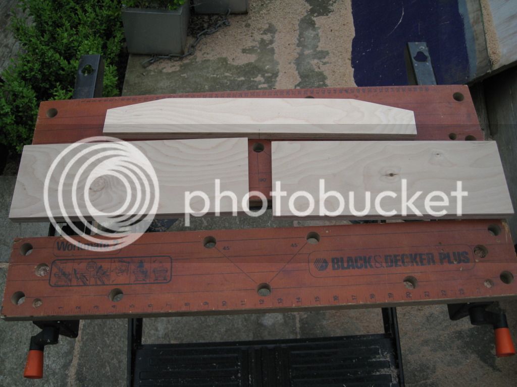
Ok well the next set of pictures haven't come that soon, but they are hear now. Following on from the fence plans I cut all the pieces, cut slots, drilled holes etc.
I am making a rather over complicated fence based on the basic new yankee design but also incorporating the micro adjustment Steve M has published somewhere in the past.
I am making a rather over complicated fence based on the basic new yankee design but also incorporating the micro adjustment Steve M has published somewhere in the past.
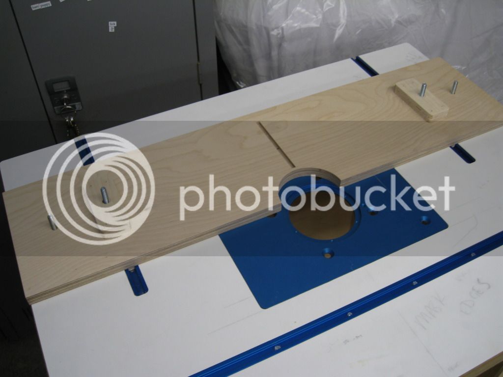
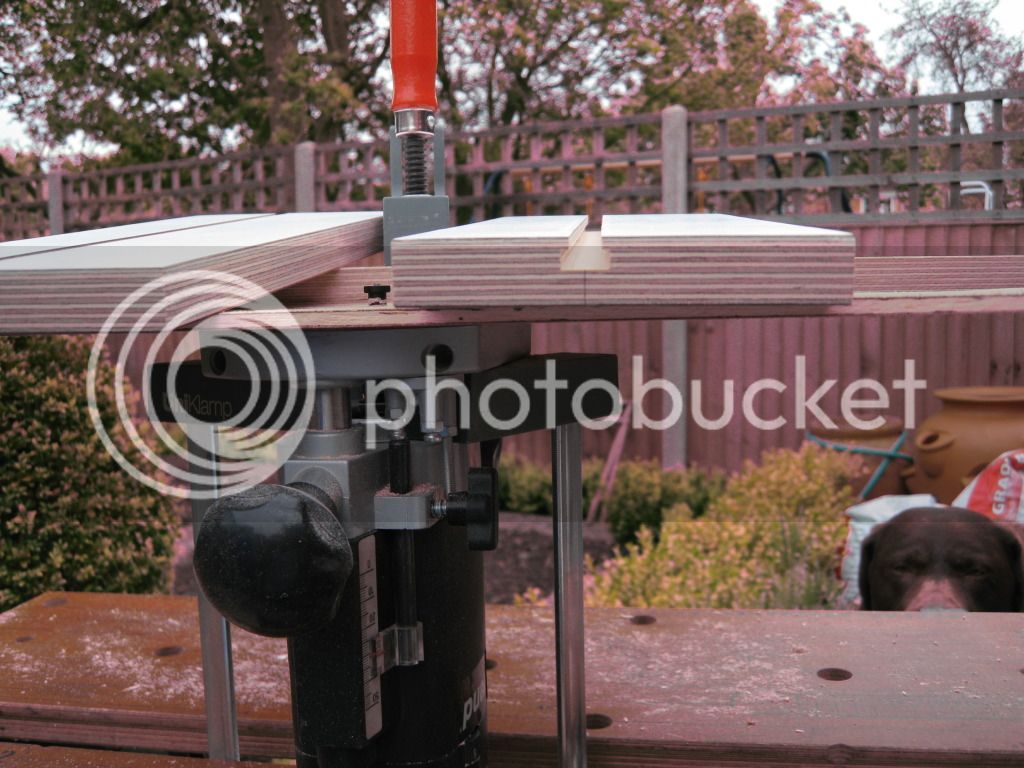
The bolts through the blocks will clamp the lower base to the table top
The bolts outside these will allow the upper base to slide independently of the lower when using the micro adjust, then lock it all together agin
The bolts outside these will allow the upper base to slide independently of the lower when using the micro adjust, then lock it all together agin
Next the 3 pieces cut for the front of the fence and laminated. 2 adjustable fence cheeks and a fixed top piece with t track for feather boards etc.
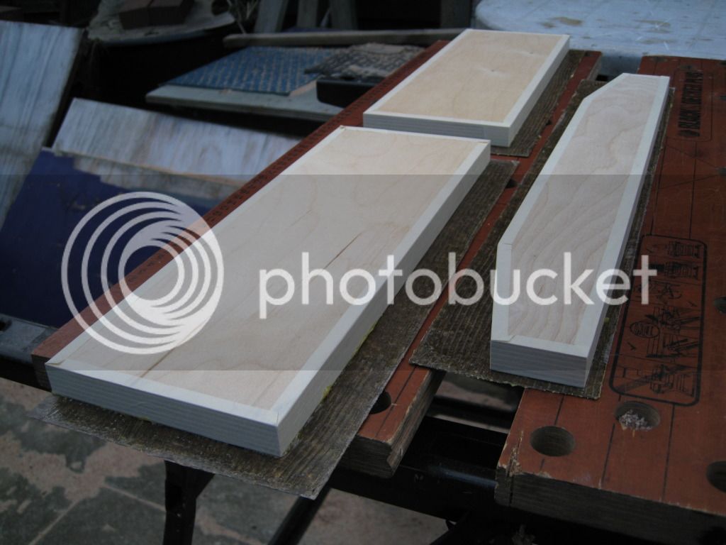
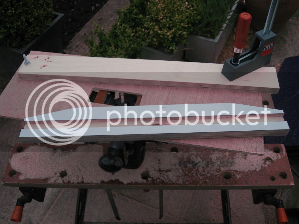
Did have one minor problem with chipping the corner of the laminate. Sods law its on the front.
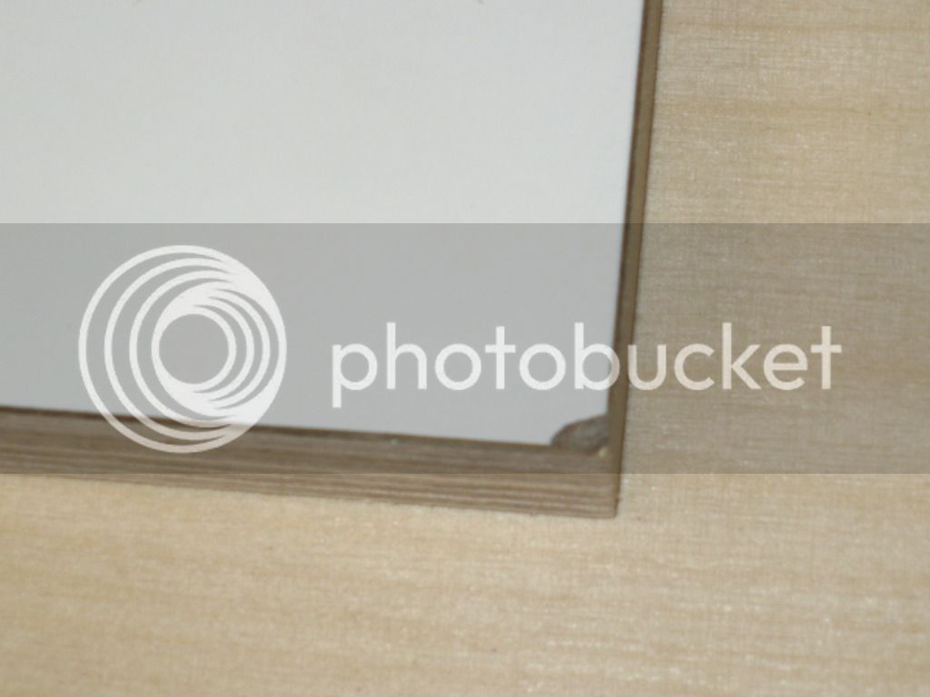
Did have one minor problem with chipping the corner of the laminate. Sods law its on the front.
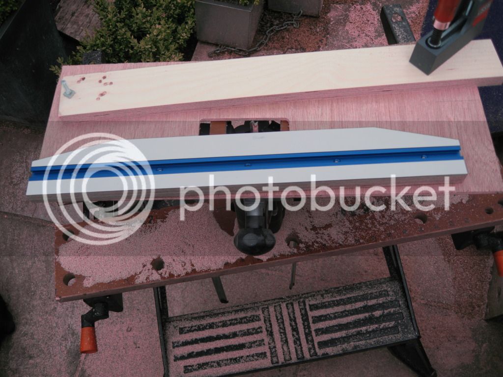
This is what it looks like at the back
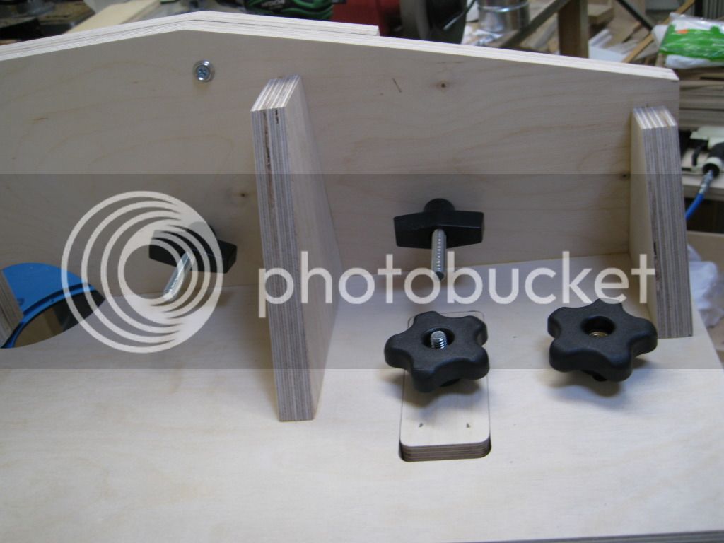
2 knobs to release and tighten eack fence cheek
2 knobs to clamp down the bases, one does the lower base to the table, one releases the upper base when using the micro adjuster.
2 knobs to release and tighten eack fence cheek
2 knobs to clamp down the bases, one does the lower base to the table, one releases the upper base when using the micro adjuster.
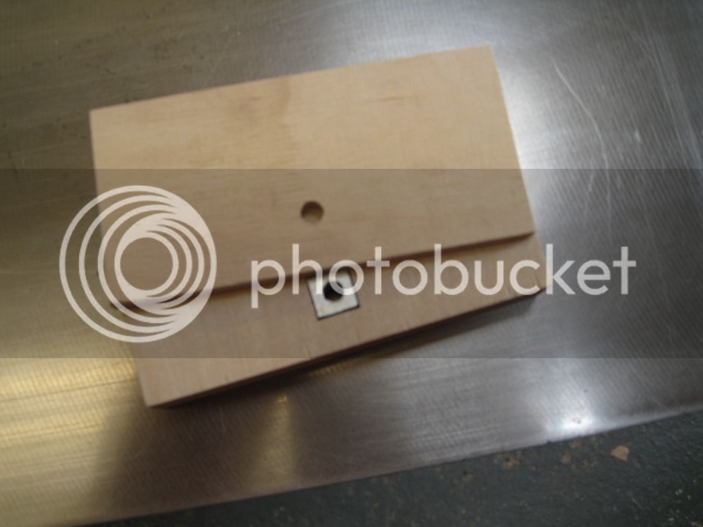
The micro adjuster pieces cut. Theory is that one turn of the bolt produces 1mm of travel. One part is fastened to each base and can be slid over each other by turning the bolt.
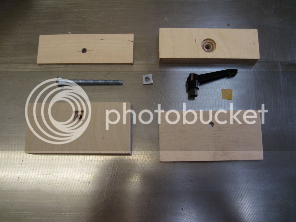
Nut embedded in the middle
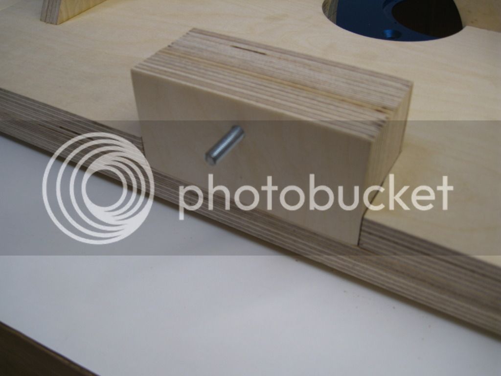
Put together
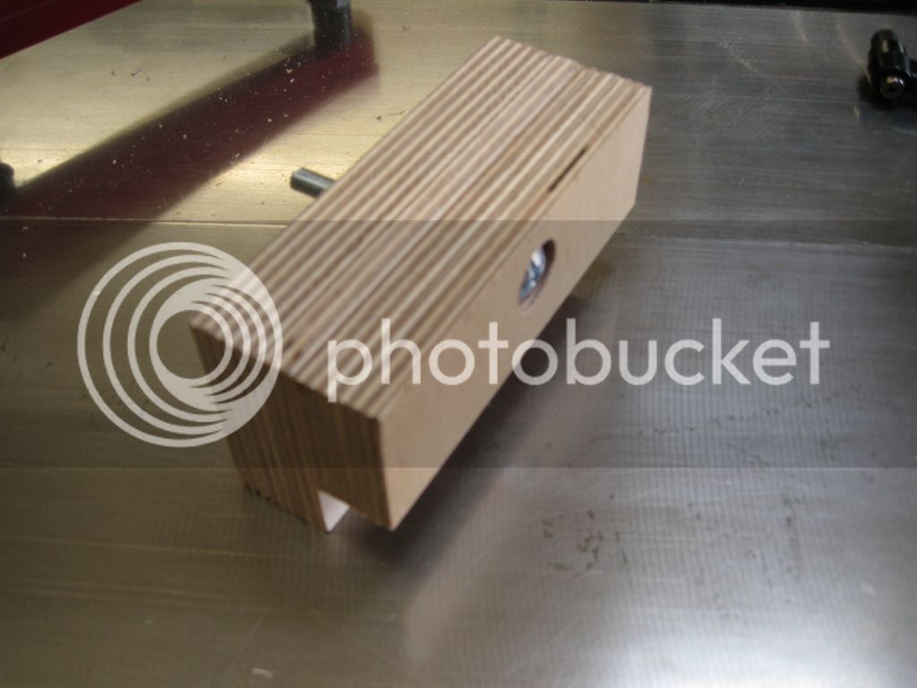
Each half fastened to each of the bases.
And the bristol lever glued on with thread lock
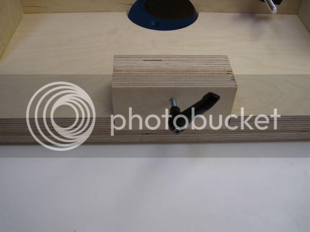
To operate, the lower base is slackened off and the bristol lever turned the appropriate amount, base locked down again and away you go. I'm rather pleased how this has turned out. I took a long time getting the pieces cut right and it moves nice and smoothly and both bases remain square to each other.
Nut embedded in the middle
Put together
Each half fastened to each of the bases.
And the bristol lever glued on with thread lock
To operate, the lower base is slackened off and the bristol lever turned the appropriate amount, base locked down again and away you go. I'm rather pleased how this has turned out. I took a long time getting the pieces cut right and it moves nice and smoothly and both bases remain square to each other.
Theres not that much more to do. I've cut the door pieces already. Main thing left is the dust extraction. I've been putting that off as I need to sort my workshop dust extraction generally. Other than that just a few bits and bobs.
Thanks for looking
Mark
Thanks for looking
Mark
andersonec
Established Member
Mark, I see you are fitting a door, you were advised at the start not to fit a door as it would not allow air flow but if you look at it, air will be allowed in around the cutter and also sucked down by the fan in the router also the door will not be a tight fit, fitting a door is to be recommended because the reduction in noise alone is tremendous. If you need a bit of perspex for the door pm me and for the cost of the postage I will cut you a piece.
Andy
Andy
Shultzy
Established Member
Mark, if you look at my router build I've made a door with a perspex front and I cut 3 holes at the bottom to aid the air draft. The door has a couple of dowels at the bottom and a magnet at the top which make it easier to open. Inside, covering the dust hole, is a cover that can be adjusted to regulate the extraction between the upper and lower pipes.
Similar threads
- Replies
- 44
- Views
- 2K
- Replies
- 102
- Views
- 7K
- Replies
- 14
- Views
- 1K