Dining Room Carver Chairs - Take 2

UKworkshop.co.uk

Help Support UKworkshop.co.uk:

This site may earn a commission from merchant affiliate links, including eBay, Amazon, and others.
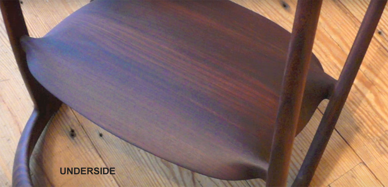
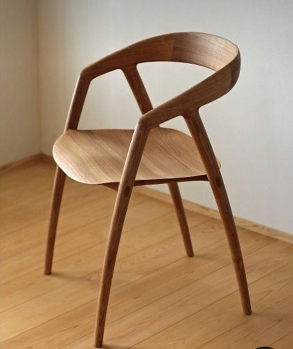
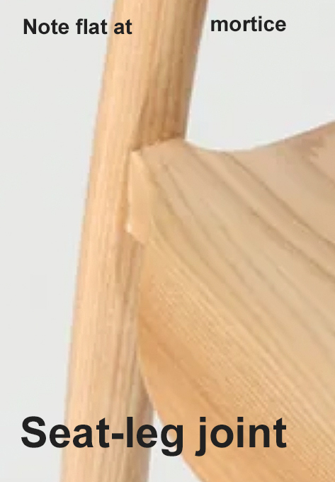
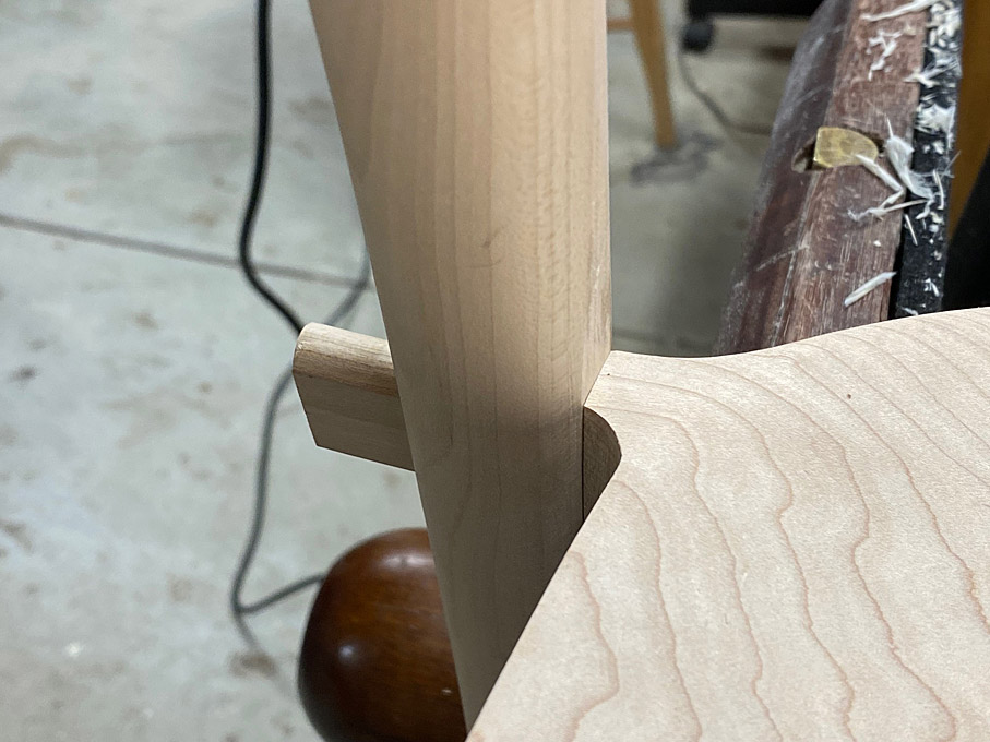
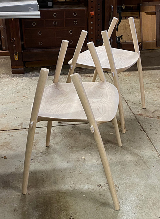
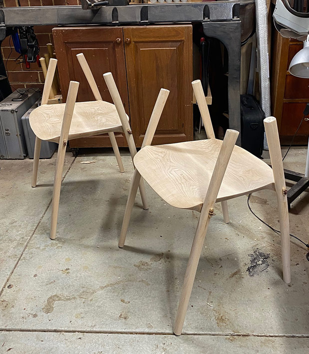
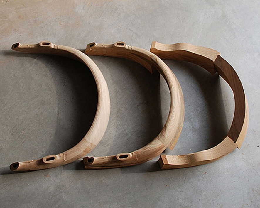
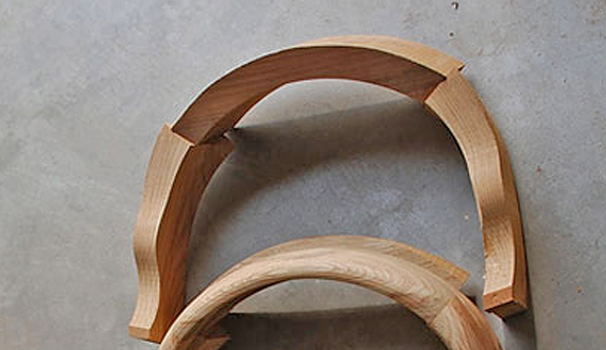
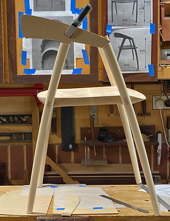
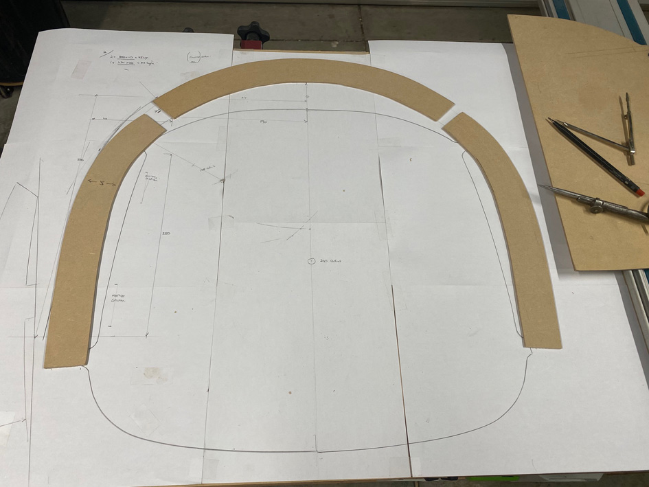
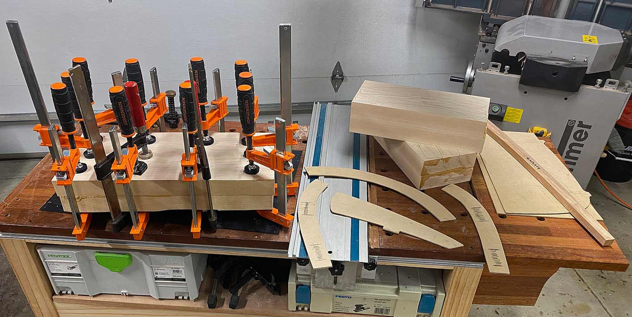
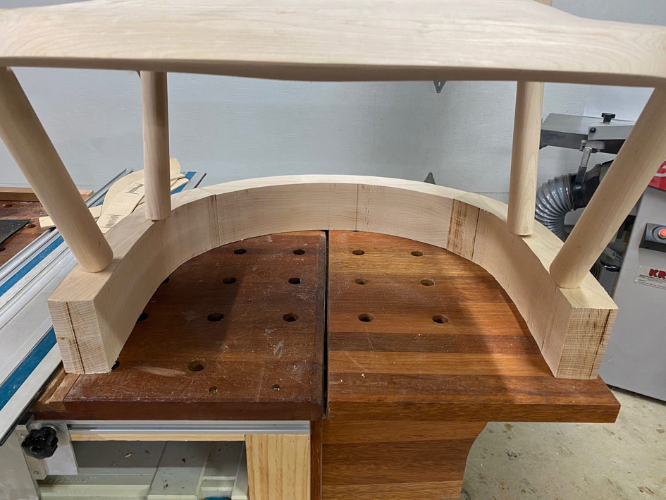
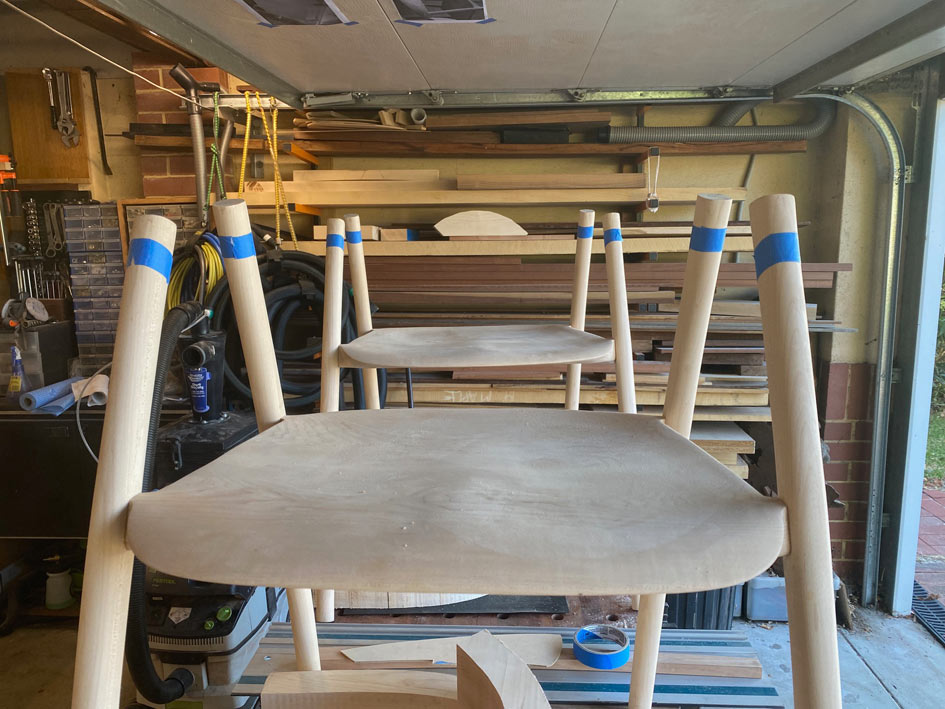
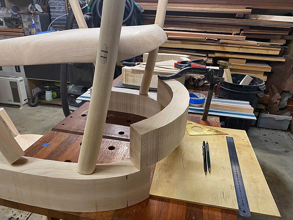
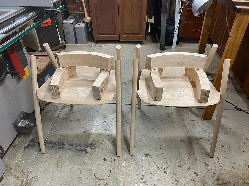
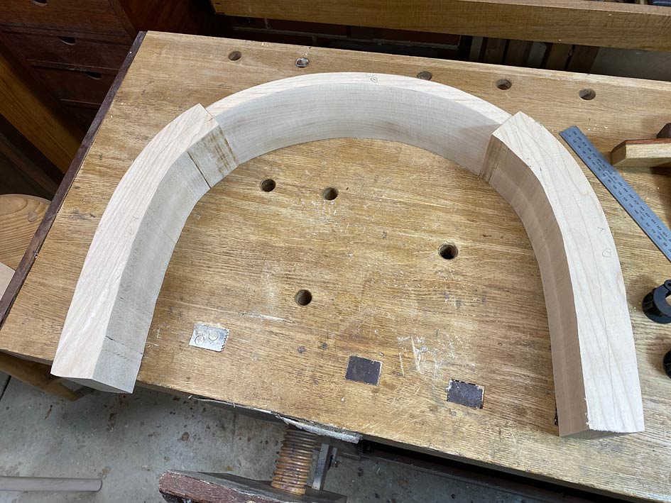
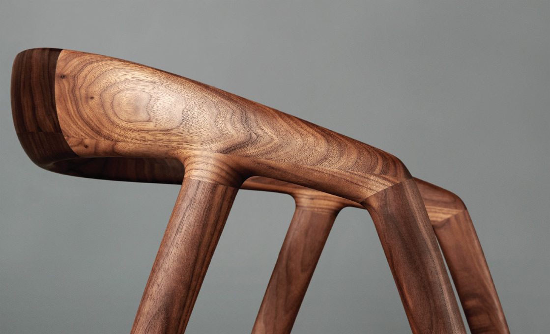
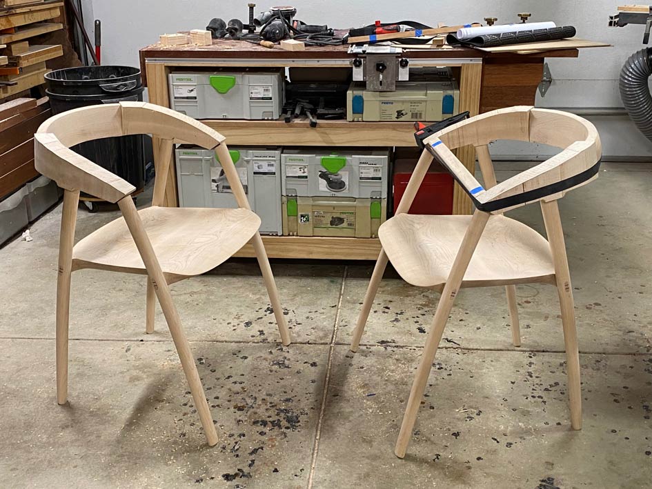
When I began this build, I looked at the legs of this chair and recognised that they were curved, tapered and oval. Well, oval at the top and round at the bottom ...

Chair2.jpg


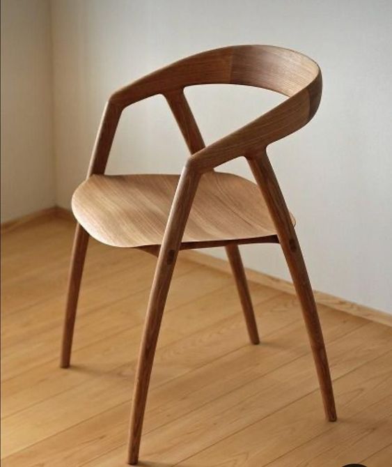
I wasn't sure how to do this - the tapered oval shape. I just accepted that I would discover this as we went along.

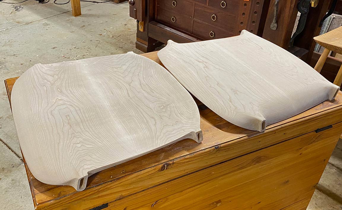
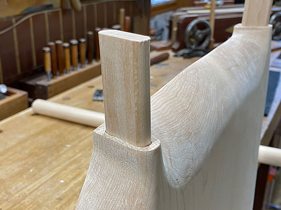
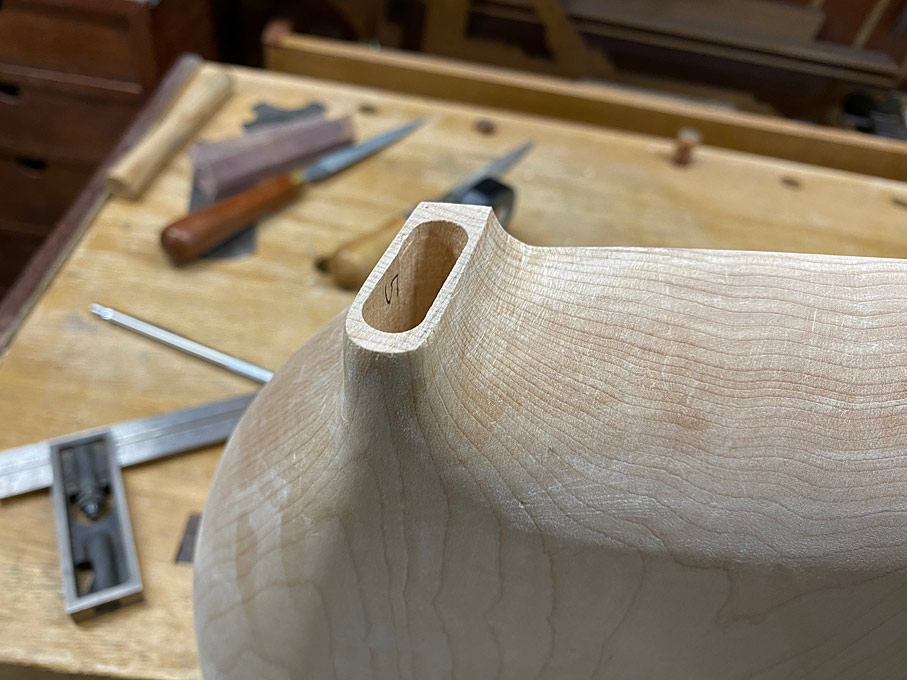
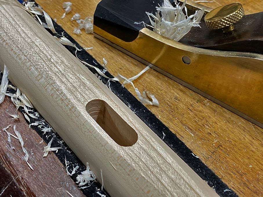
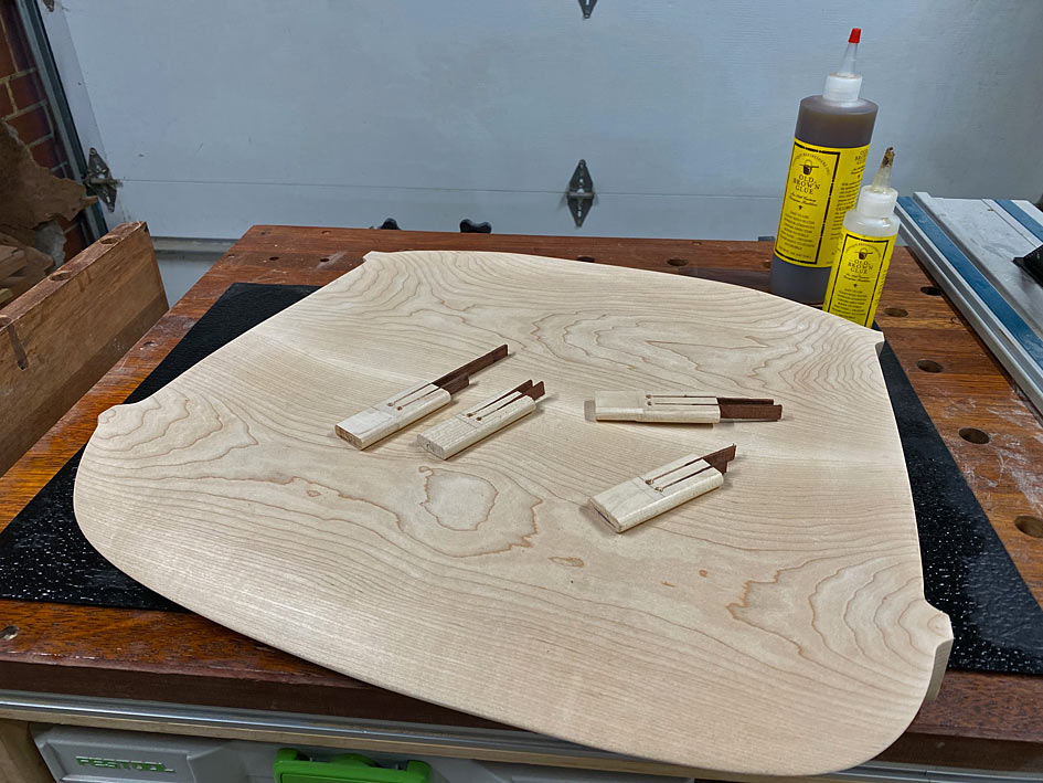
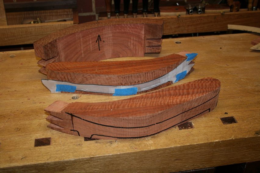
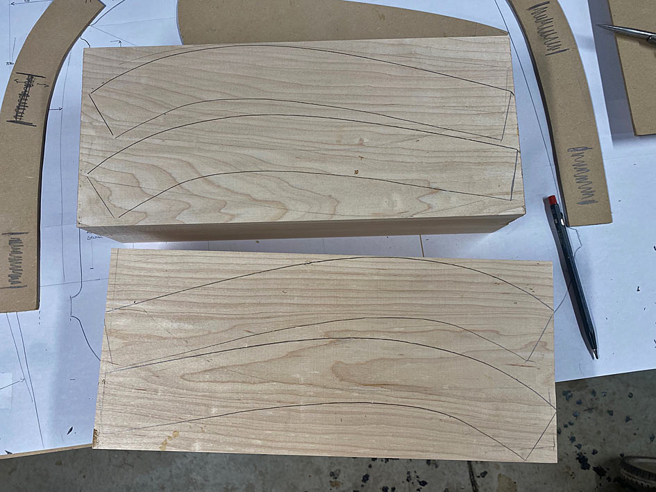
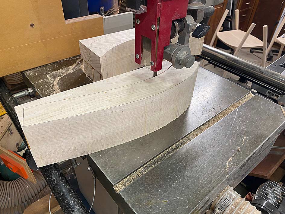
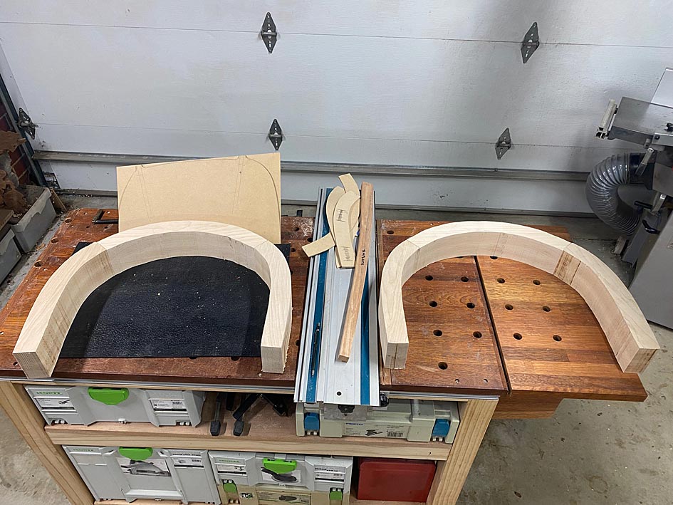
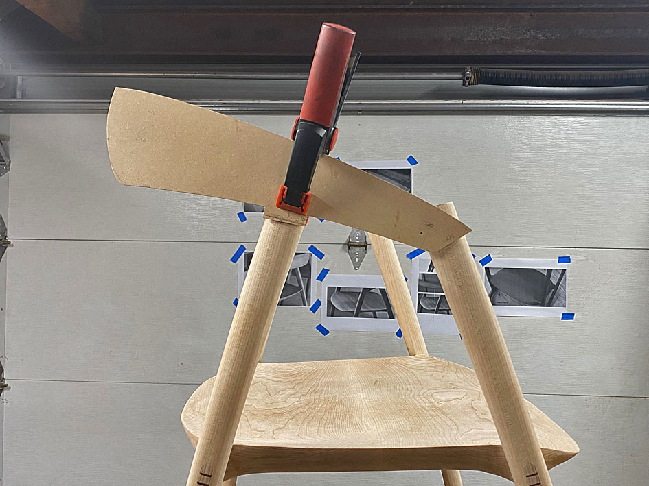
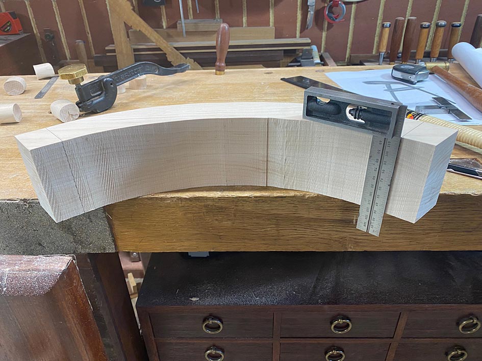
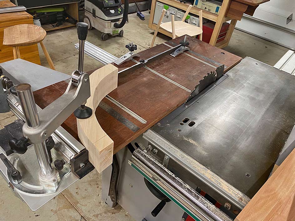
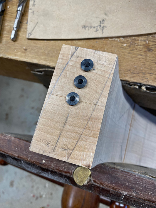
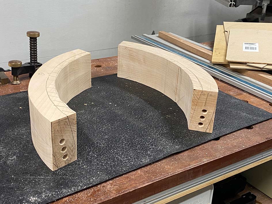
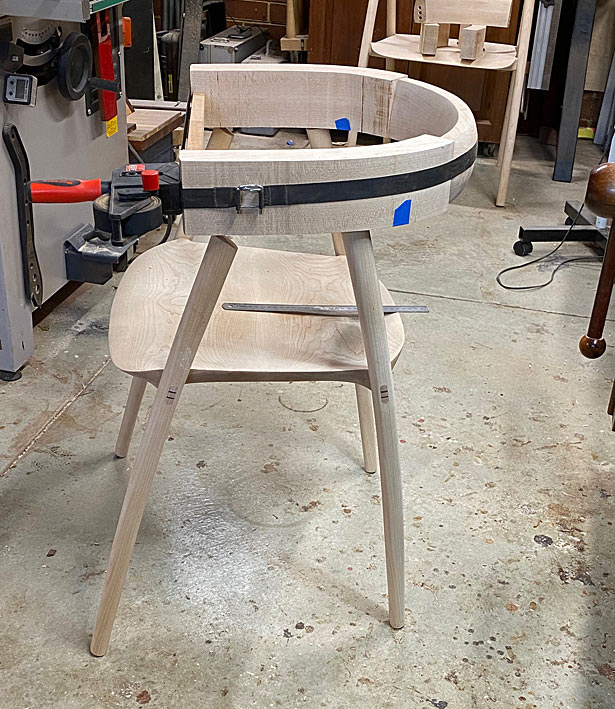
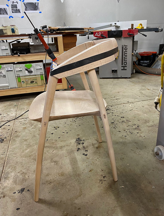
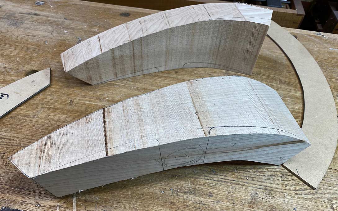
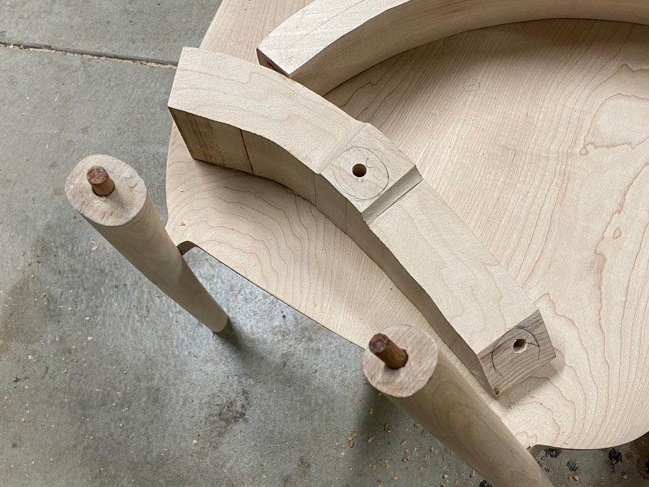
I began by shaping the legs in profile and cut the mortises ...

L8.jpg


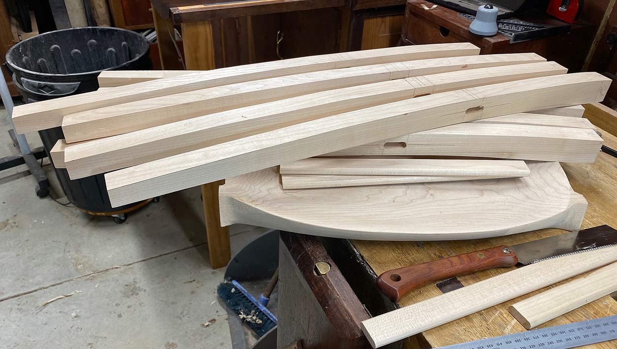
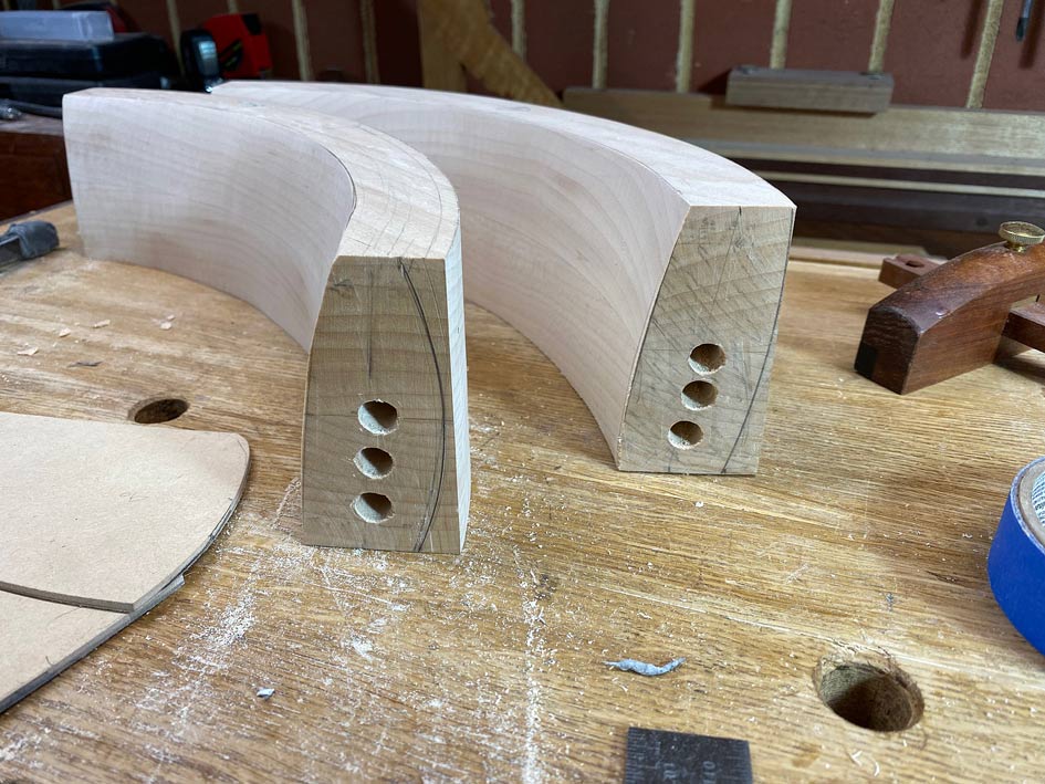
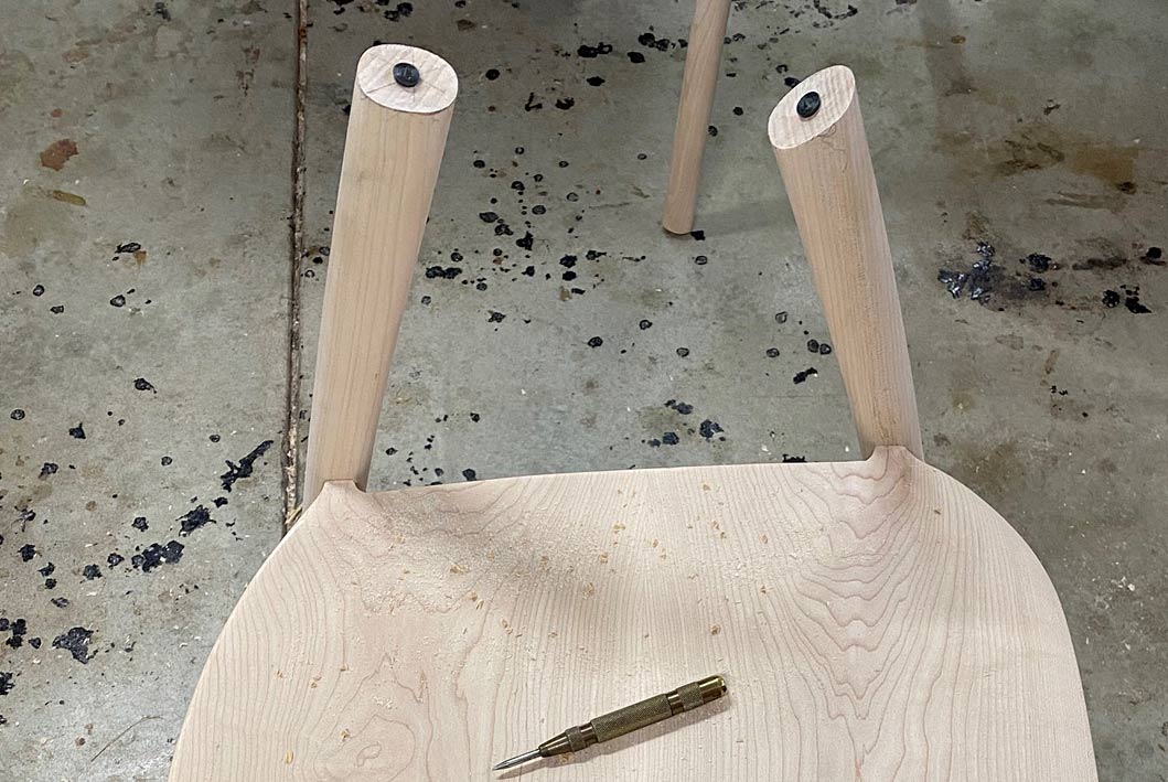
Then knocked off the corners with a round over bit. The leg at the rear was an attempt to do all with just spokeshaves - not great. The round over provides a helpful guide ...

L9.jpg


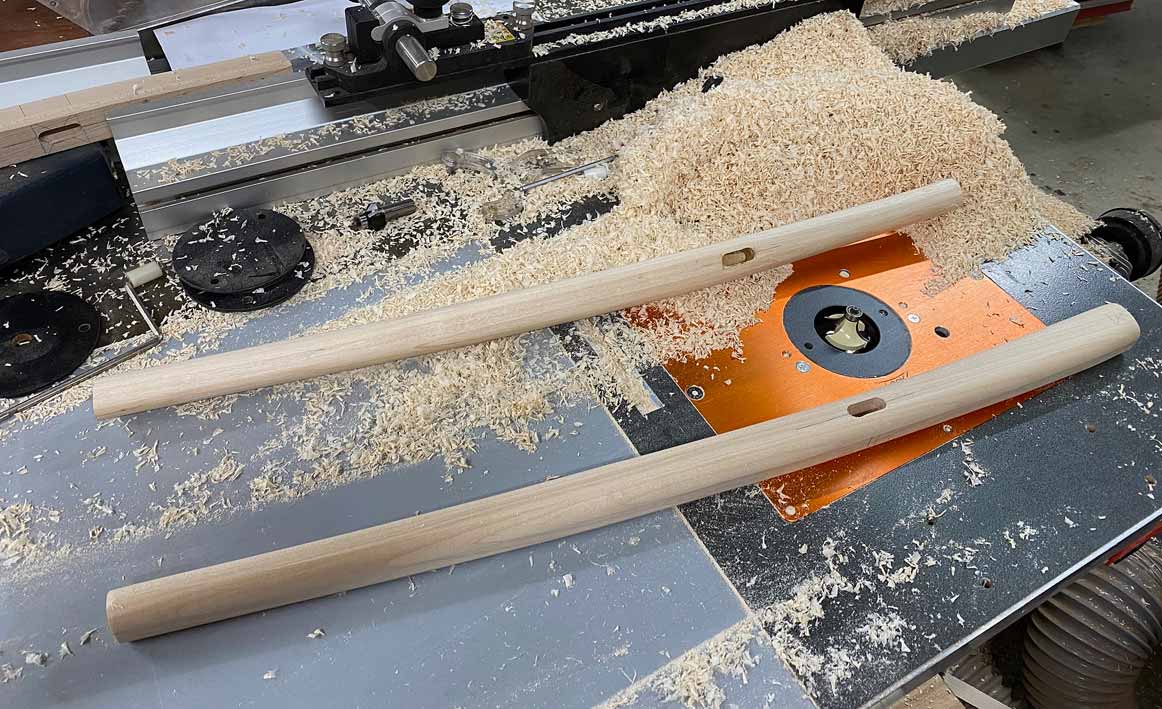
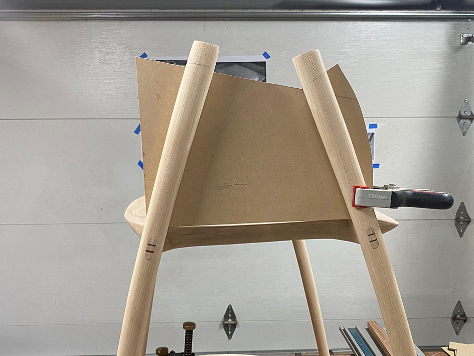
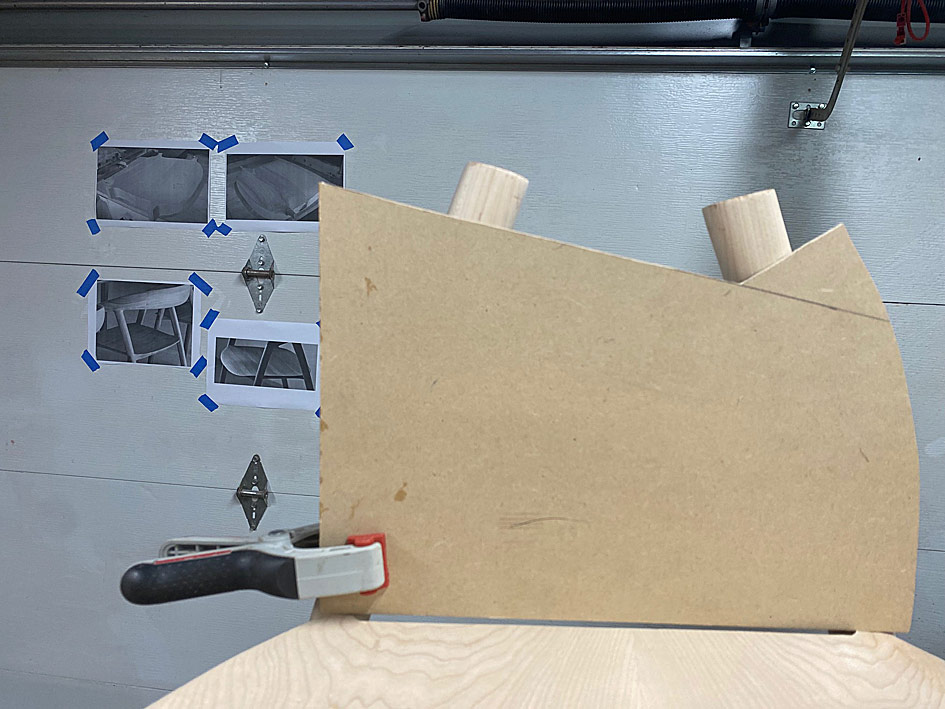
This left them rectangular with rounded corners. This weekend the rectangles became tapered ovals.

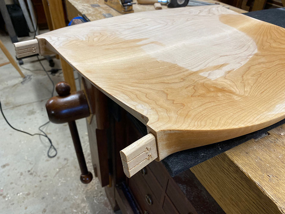
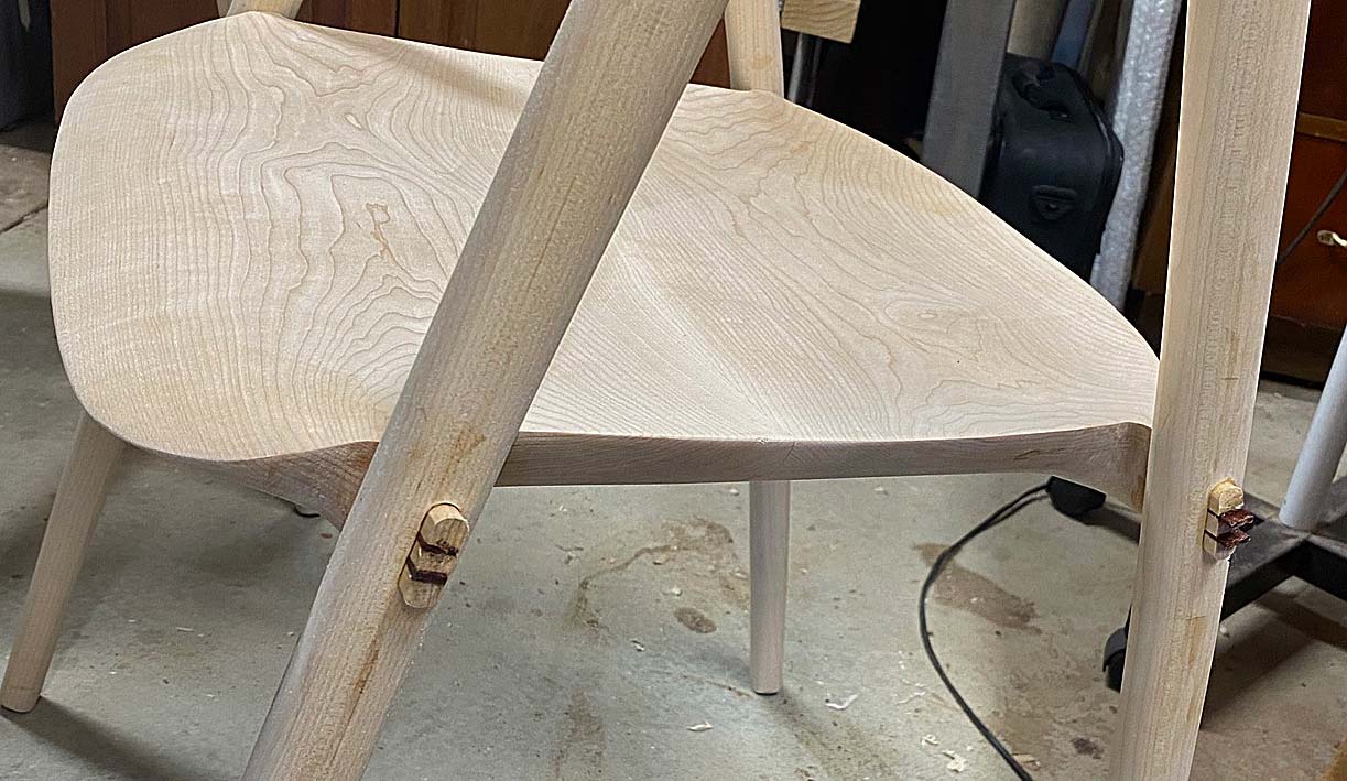
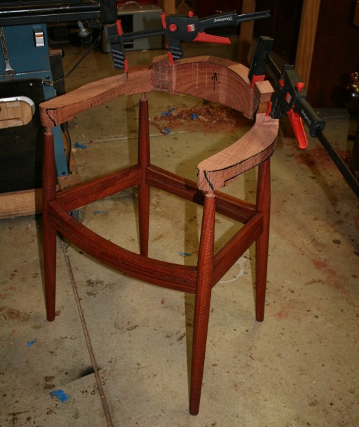
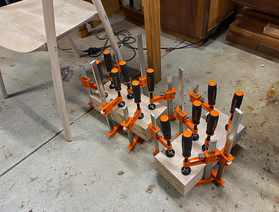
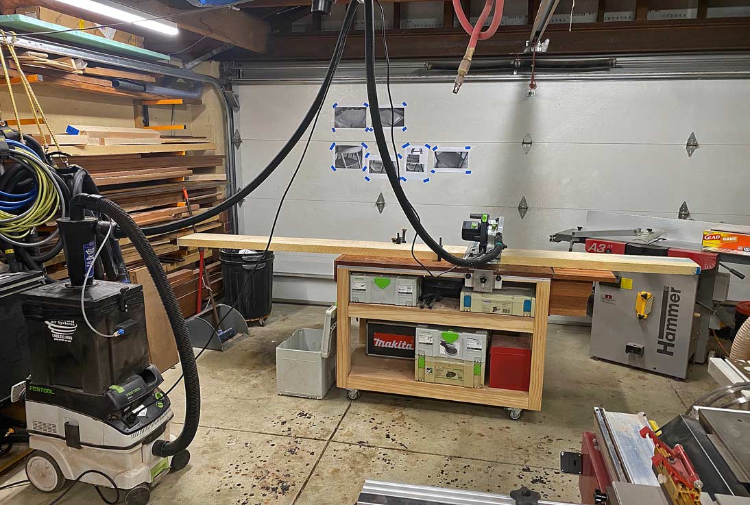
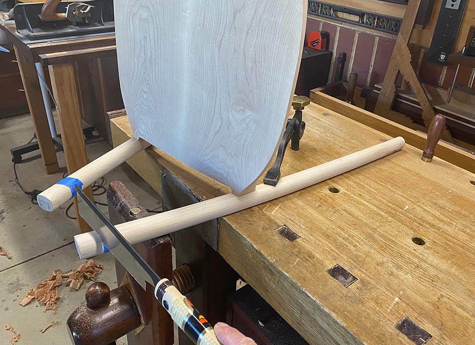
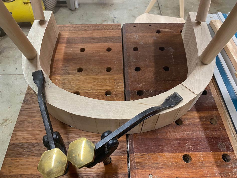
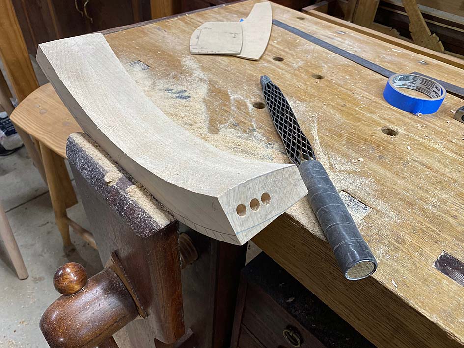
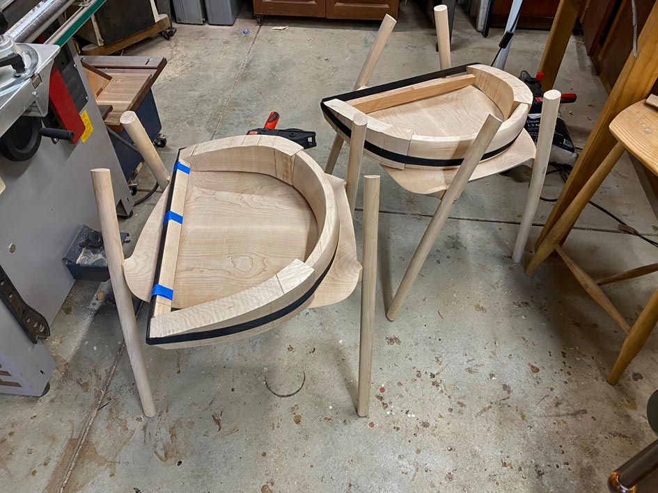
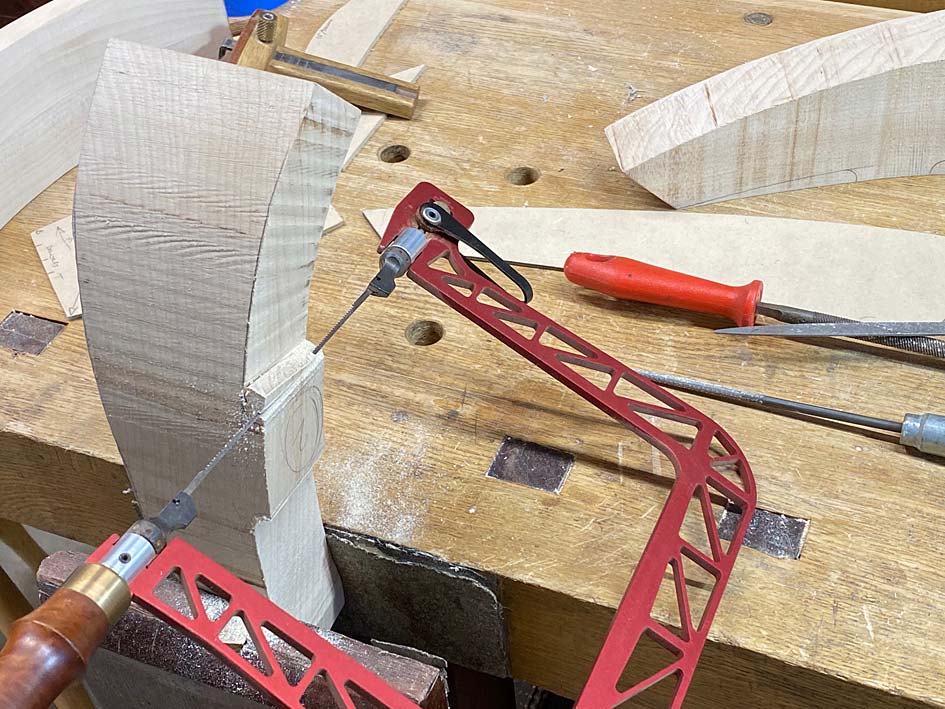
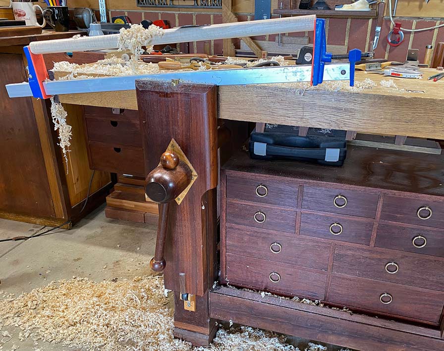
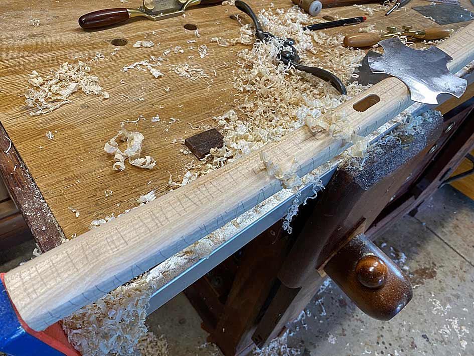
Working at the bench, holding the legs in a clamp ...

LL1.jpg


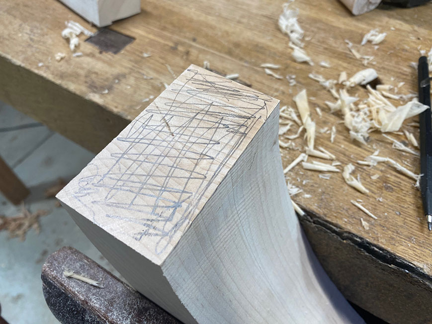
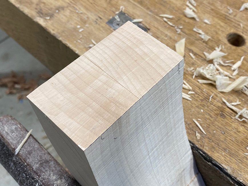
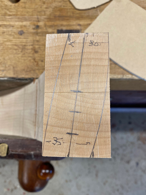
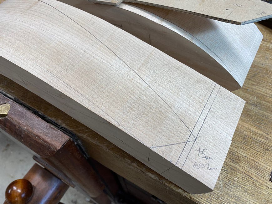
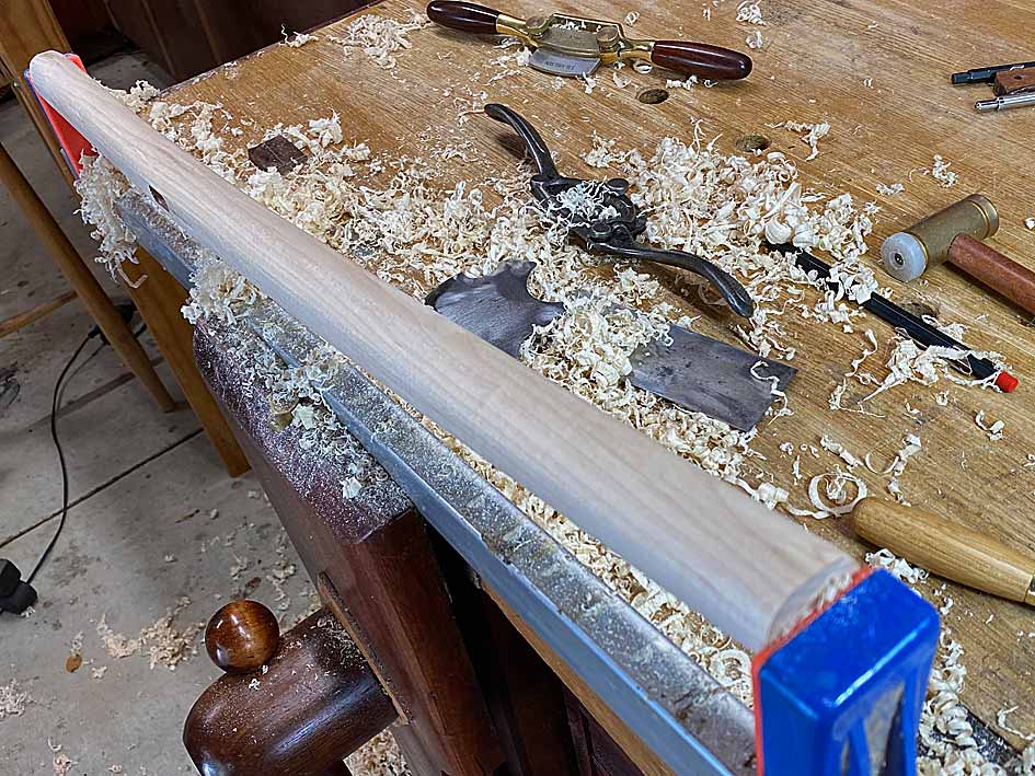
The first step was to cover the legs in pencil scribble. The purpose here is to make it easier to see where I am working. This Rock Maple is so light in colour and difficult to pick up details.

LL2.jpg


LL3.jpg


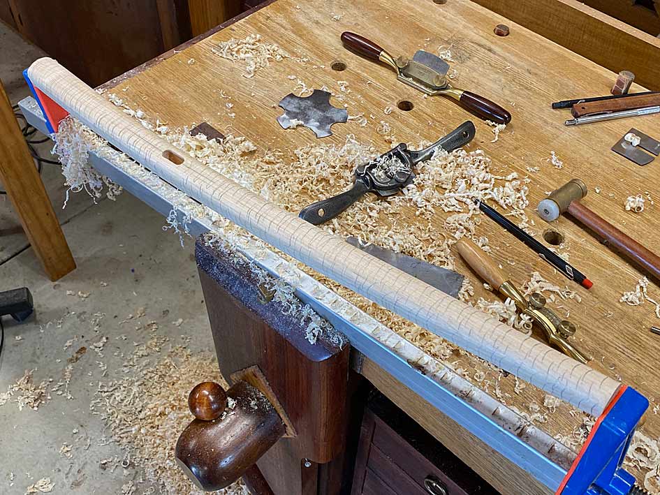
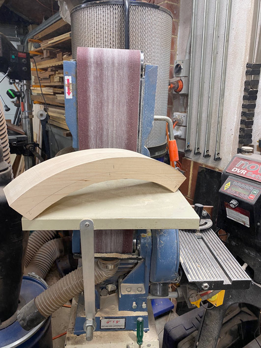
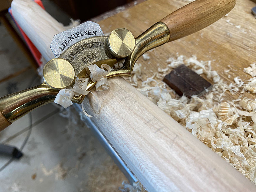
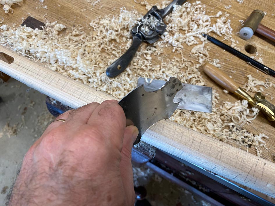
Some of the waste had already been removed by spokeshaves, but now the final shaping needed to take place. The tools used were a convex spokeshave and a set of convex scrapers - different sizes.

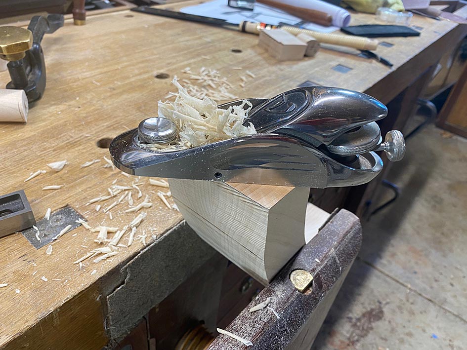
Once sharpened, the scraper make nice shavings ...

LL5.jpg


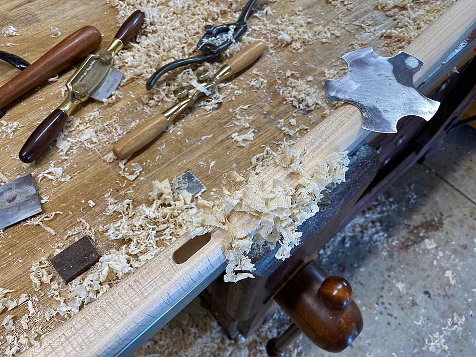
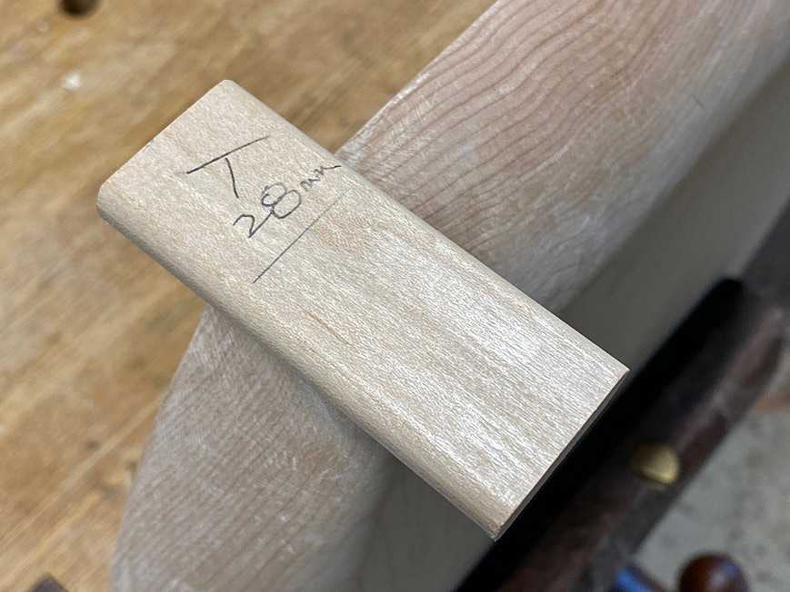
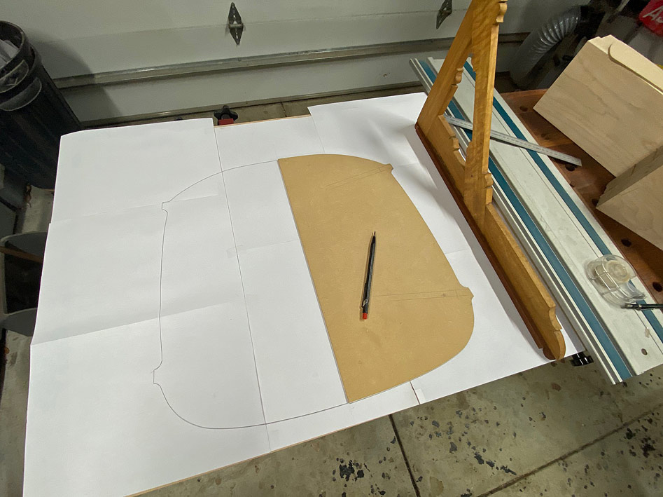
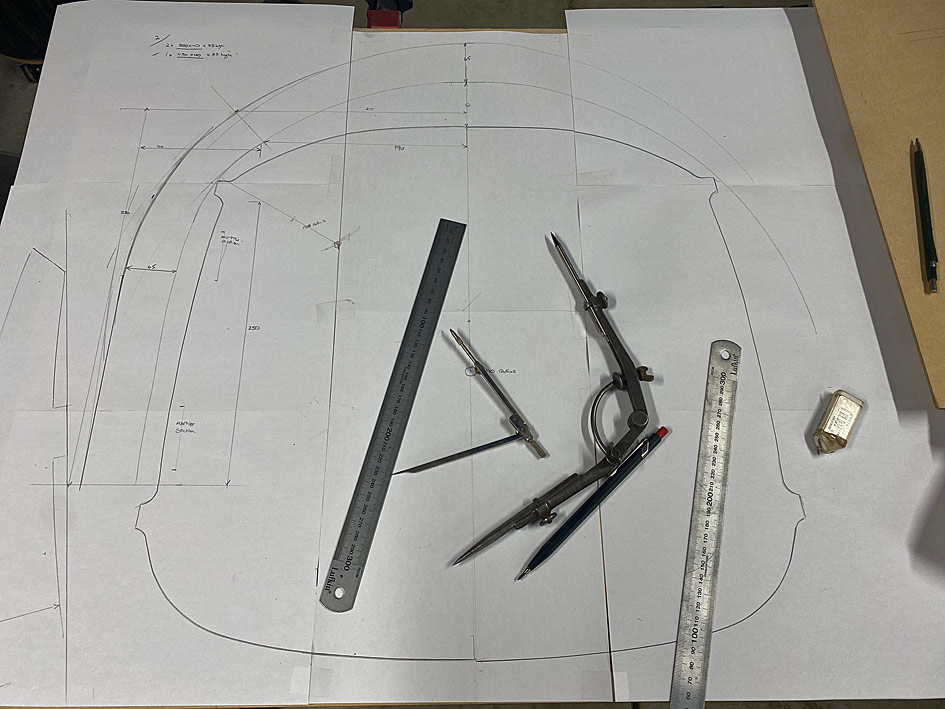
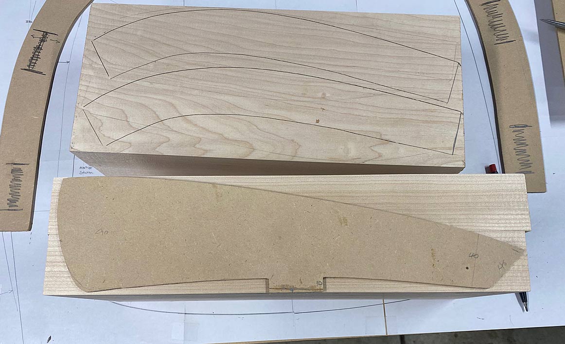
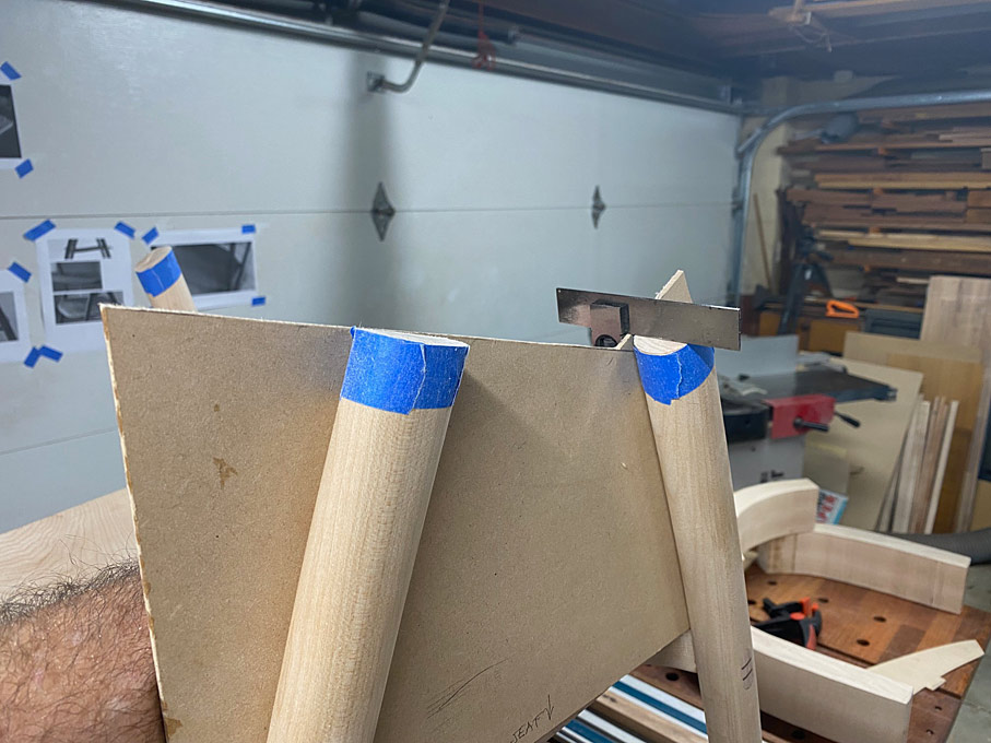
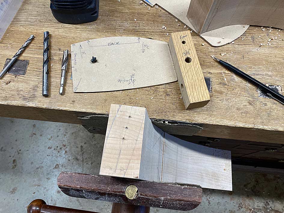
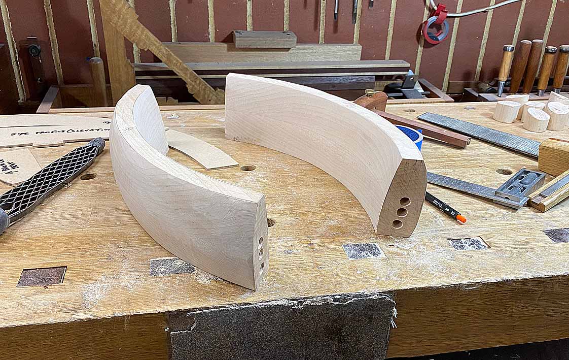
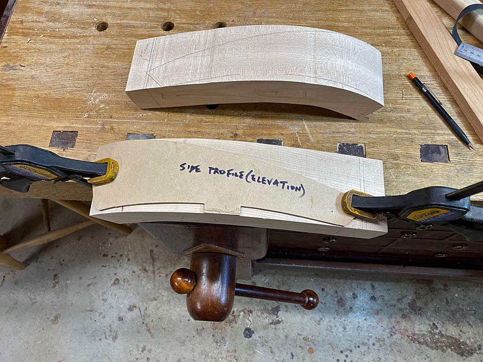
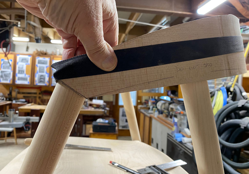
The scrapers also provided a template for the curves to be retained on the legs. The taper on the sides of the legs goes from 40mm at the top to 30mm at the mortice to 25mm at the feet. The edges (facing forward and rearward) is a uniform 30mm. So this meant that there was a single convex scraper for the edges and two scrapers for the sides.

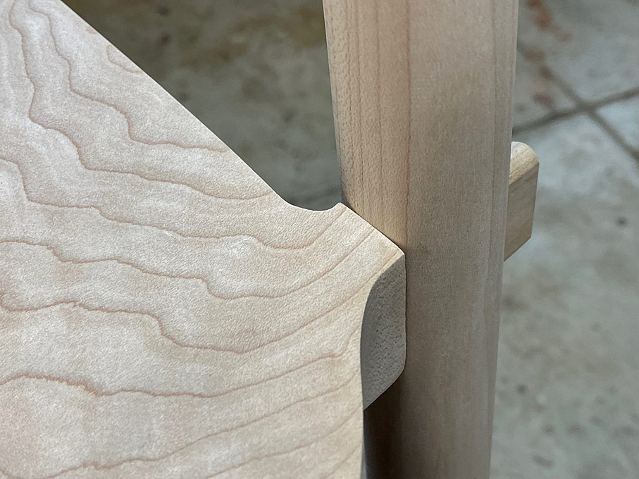
This is the difference between a scraper and the leg ...

LL4.jpg


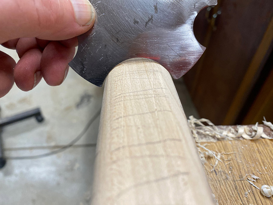
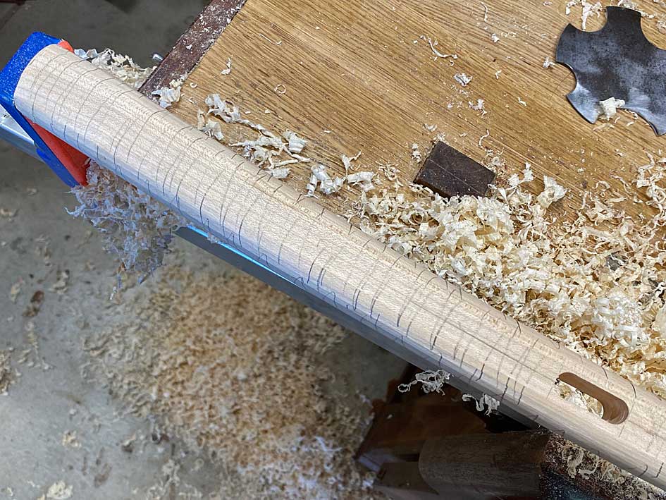
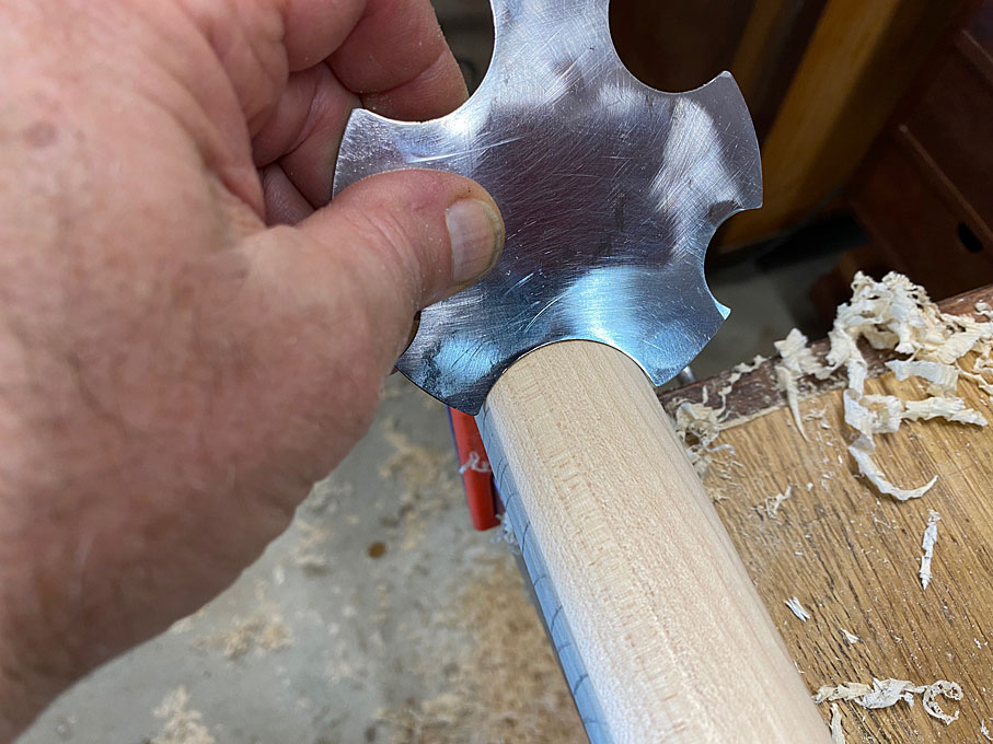
Running it along the leg reveals the low section through the centre ...

LL6.jpg


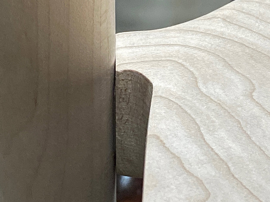
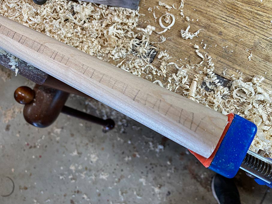
As you work down, so the curve increases, and the high spot gets smaller ...

LL7.jpg


The convex spokeshave helps out ...

LL8.jpg


Also, angling the scraper allows a wider cutter to follow the outline of a narrower section ...

LL9.jpg


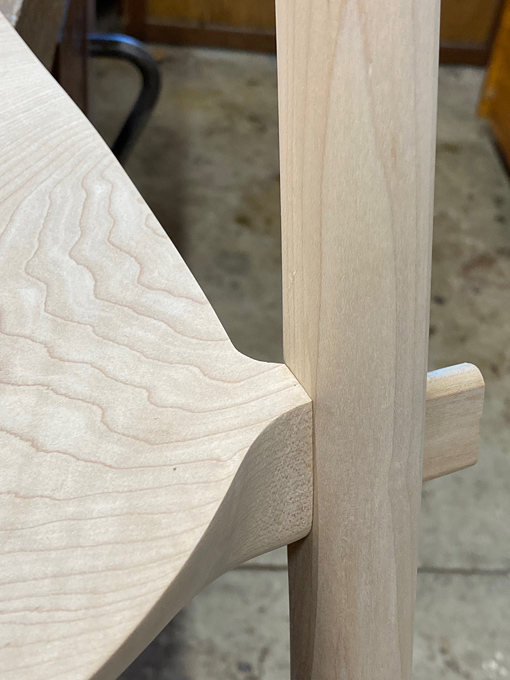
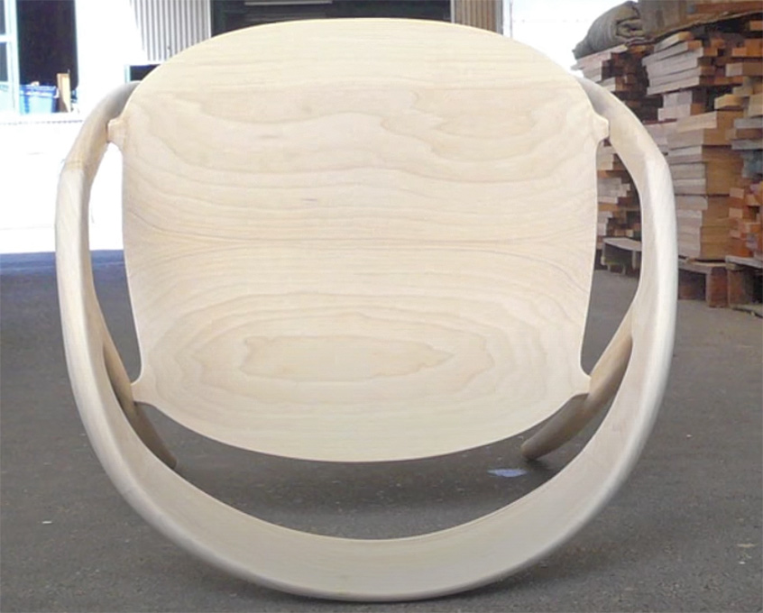
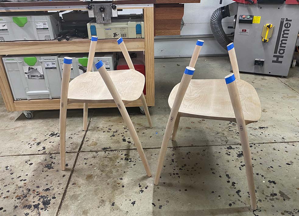
Eventually, the scraper and the leg share the same profile ..

LL10.jpg


LL11.jpg


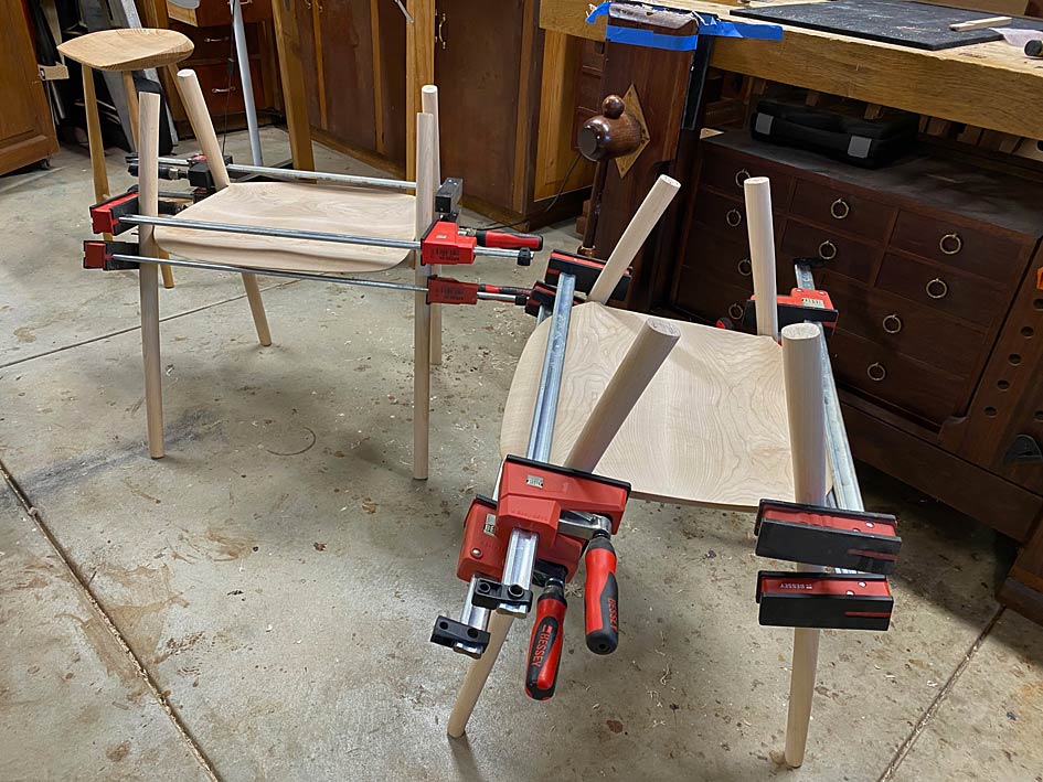
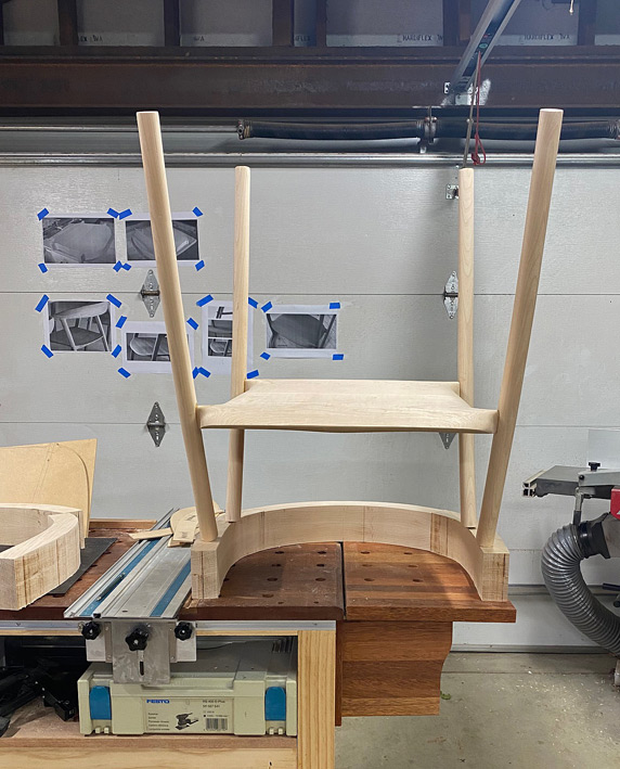
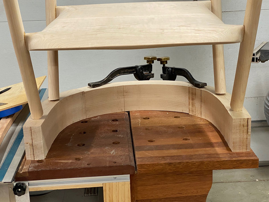
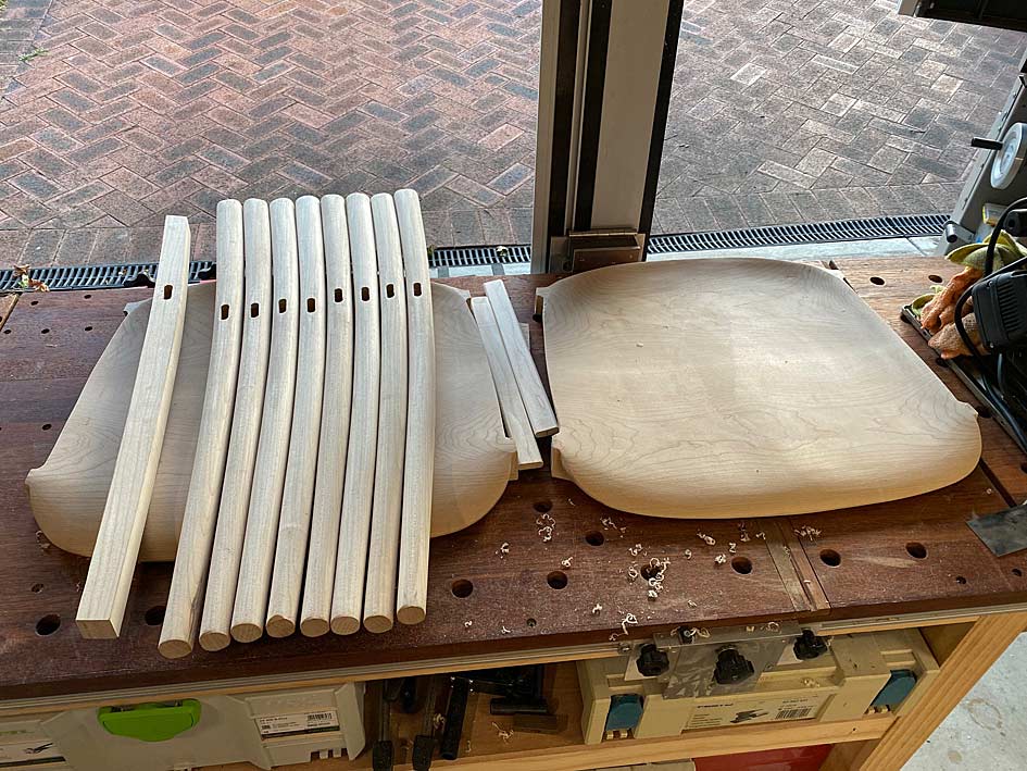
Lots of work on a very humid weekend. All legs completed now ...

LL12.jpg


Regards from Perth

Derek
 
I must admit that this is an unusual build for me. I literally do not know what I am doing ... insofar as I have to keep returning to parts to refine and refine them. That is what is so time consuming. I don't always score high on being sensible, but I do on perseverance and being bloody minded!

Today was not a work day, and I ear-marked completing the seats. The upper side was 99% done, but the underside needed fine-tuning. I have two photos to guide the shaping ...


That one (above) is from the factory building the prototype. They screwed the legs to the seat, rather than use integrated tenons. This proved to be a great model in my case.

The second photo is a production chair seat taken from the underside. In particular, this shows the treatment of the smoothing of the tenons and their integration with the back ...


Lastly, I keep returning to this photo of the chair, which shows how thin the seat looks from the side. Keeping in mind that the seats started out at 50mm, and were 40mm after the plan was cut out, a great deal of tapering was necessary to achieve this look ...


Here are the two completed seats. The seat on the left is face up, and the seat on the right is bottom up ...


Regards from Perth

Derek
 
Today we reached the milestone I was patiently (okay, not so patiently) waiting for - glueing up the legs and seats. To get to this stage, however, required matching the mortices with the loose tenons, matching the loose tenons with the leg mortices, cutting slots for the wedges (into the tenons), and shaping the tenon mortise to fit the legs.

Let's start with the obvious. This is how the tenon and the tenon mortise will end up looking ...

T2a.jpg


The loose tenon is 30mm wide and 10mm thick. It extends 28mm into the tenon mortise ...

T3a.jpg


This all looks rather neat, but it was the end result of further shaping to fit the legs with the seat. The issue was that the seat mortices were chunky ...

Seat1.jpg


When joined, this was the fit ...

T4a.jpg


T5a.jpg


Two steps were involved. Firstly, the tenon mortise was reshaped to be thinner at the face (this involved removal of waste at the top edge and not the sides, which is needed support for the loose tenon) ...

T6a.jpg


Secondly, the face of the leg mortise was planed flat to match the face of the seat mortise ...

T7a.jpg


This is how the original chair was fitted - photo I posted early on ...

Seats3.jpg


This is the result ...

T8a.jpg


T9a.jpg


All the parts fitted, but not yet glued up ...

T10a.jpg


Loose tenons slotted for wedges, along with the wedges. Glue of choice: Old Brown hide glue. Why? Because at some stage in the future, hopefully many years from now, it is likely that the joinery will need to be re-glued.

T11a.jpg


The seat tenons are glued first and the glue allowed to dry (they are a bit long here, and were cut shorter before the legs were attached) ...

T12.jpg


And a last photo of the final glue up. It will remain so for 24 hours.

T13.jpg


Starting to look like chairs! ;)

Regards from Perth

Derek
 
Hi Derek,

This is a really interesting thread, and I'm enjoying following it, but, have you not snookered yourself by gluing up at this stage? I appreciate that it's good to get things fixed, so that one can move forward but I would be worried that the tops of the legs are not in their correct position in space or in relation to each other.

I have to admire your confidence ,as I would have been tempted to keep things more fluid, by only dry jointing, at least until I had sorted out the back/arm section. I assume you are using simple tenons at the tops of the legs and not using finger joints reinforced with a dowel where the top meets the front legs?

I'm looking forward to seeing how you tackle this next stage, with interest

Niall
 
Hi Niall

Good question, as it goes to planning ... which this entire thread has been about.

The legs need to be trimmed at the feet for level, and above the seat they are over long at present.

The arms and back will now need to be designed and planned out. This section will be mortised (dowled) joined, and so sit on top of trimmed upper section. That is why the glue up important - to prevent any movement.

Regards from Perth

Derek
 
Last edited:
A note about wedges

This is a cross post from the Australian forum, where I was asked for more information about the wedged through tenons.


I am not sure if the photo provided must detail, but the wedges are tapers, but also long and skinny ...


They both fill the slot - which is full of glue - and create a wedging action, firmly pushing the tenon edges against the glued insides of the mortise. The mortises, both in the seat and legs was 30mm long. Most were exact, some of the legs were a little under a mm long. A little filing for all to create this tiny gap - it does not have to be more. The glue is enough and the wedges are security. Interestingly, this appears to be the same in the original chair, with the exception that they added a chamfer for the end of the wedge. I've never seen this before ..


In addition to the wedged legs (I am trusting that the small amount of taper inside the mortises will add an extra layer of solidness), the arm/back structure adds stiffness and resists the legs wracking/moving. It is akin to triangulation of the construction (not really triangles, of course).

I have removed the clamps and the structure is really stiff already - I will wait until Lynndy is out of the way to take some photos. She-Who-Must-Be-Obeyed is keeping a steely eye on my "taking it easy" today!
anoyd.gif
[Explanation: I was in hospital yesterday for an op on my left torn patella]

Later:


I snuck into the workshop to unclamp the glue up. Lynndy caught me! But she then asked to sit on one of the chairs (sans the arms and back). She did so gently, and then with all her weight (55Kg). The seats did not even sigh, and nothing moved. She proclaimed the seat very comfortable. Yay!

Tenons and wedges yet to be cut and levelled ...


Regards from Perth

Derek
 
Beginning the arms and backs


The legs and seats are done and it is time to move to the arms and backs. Once again, the chair to provide a context of where we are headed ...

Chair2.jpg


I was fortunate to find a few photos on the Web showing the development of the arms/back, which provided some insight into how to construct this ...

Seats4.jpg


The construction sequence that was really helpful was this (note these are from the underneath) ...

Arms1.jpg


While this makes it all appear accessible, my experience building a Hand Wegner chair prepared me for the large chunks that make up the two arms and the back ...

TheChairShapingArmsBackPart1_html_m11f0c459.jpg


Giant slabs and lots of carving (since, unlike the factory, I do not have a CNC machine) ...

TheChairShapingArmsBackPart1_html_m2b87da0c.jpg


But look at the first photo in that sequence - the back is angled into the arms. Wonderful - less to carve!

Arms2.jpg


The arms need to be shaped from blocks 90mm high, so I got busy laminating ...

Arms7.jpg


And while this was drying, time was spent on getting the profile for the side of the arms ...

Arms3.jpg


There's a photo on the wall behind against which to compare. Also, a first look at the completed through tenons.

That's the easy stuff. Time to design the arm and back profiles.

We start with a seat ...

Arms8.jpg


... to use to frame around ...

Arms9.jpg


After much back-and-fro drawing, rubbing out, re-drawing, and transfering to MDF for templates ...

Arms10.jpg


Each of the blocks (seen beng glued up earlier) create four arm blanks ...

Arms11.jpg


Here is the side elevation ...

Arms12.jpg


Wood for the backs came from sawing up this 3m long board ...

Arms13.jpg


And, for now, the backs are laminated and drying alongside the other blanks and templates ..

Arms14.jpg


Tomorrow I shall begin cutting it all up, and joining pieces together.

A question for all is how you might connect/join the arms with the legs? Note that the back will be joined angled to the sides, as per the photo.

Regards from Perth

Derek
 
More of the arm jigsaw


Here is the work done today, which was preparing the arms before shaping. Critical work, and the day went well. This was mainly due to working methodically. Looking back it all seemed so logical and straightforward, but it didn't feel this way before hand.

The first task was to bandsaw all the blocks of wood into shape, having outlined the parts with the templates.


Lining up the arm parts for two chairs, three for each ...


At first I thought I would clamp them together and balance the lot on top of each chair ... no, that would be silly! :) The chairs were turned upside down on the arms ...


This revealed that the spread of the arms was a little too wide. The arm supports need to be centred on the arm rests ...


Before adjusting this, the next stage needed to be to cut the arm supports to length. To do this, first the template for the arm elevation was positioned ...


... and then a template was made to position this ...


This allowed all the arms supports to be marked on both sides ..


.. and marked with blue tape ...


The excess is sawn away ...


The template also enables the accuracy of the saw cuts to be checked, and for square. This will need to be fine tuned later, but good for now ...


The underside of the arms are marked so the positions on each will be the same, and the overhang at the rear was roughly calculated. Again, this will be adjusted after the arms parts are joined.

Now the top rail can be positioned for sizing ..


It is marked for sawing ...


Aligned on the slider ...


All the ends of the arms are squared this way, however the saw has a maximum cut height of 75mm and these parts are 90mm. This leaves 15mm to saw away with a hand saw, and then clean up with a block plane. This clean up is important as it is also jointing for the parts to fit together gap-free ...


The arm parts are ready to fit together ...


And all done for the day ...


Regards from Perth

Derek
 
Arms - part 1

The key piece is the top rail, and the key element here is the rear curve. Here it is smoothed on the belt sander. It will be a reference side for marking curves ...


The angles I have had to guestimate have been the tilt, front and rear, of the top rail. This is what I came up with ...


The plan is to join the arms using dowels. The Rule of Thirds applies. 3 x 3/8" dowels (3/8" = 9.5mm, which is close to the 10mm tenons used previously). Why dowels? Because they are easier to position accurately without a reference edge.

Since a large amount of waste will be removed from the top rail and arms, through shaping, the dowels need to be positioned where they will not be cut into. The three marks on the ends of the top rail are the position for the dowels. The wooden block was a quick guide to drill vertical as it needed to be done freehand ..


The only complication was that I had 6mm dowel centre points. It would have been easier if they were 3/8". Nevertheless ...


Drilled for 3/8" dowels in Jarrah (I have a bucket of them), each close to 50mm (2") in length.


Everything is still a rectangle at this stage ...


The inside face of the top rail is shaped ...


It is at this point that I have a re-think about the curve of the rear - it is not a fair curve and enough curve when compared with the photos of the DC 09 chair. The re-drawn curve on the left looks correct to me now, and this is what we will go with ...


The parts are joined up as a loose fit (using undersized dowels)...


The arm/rail combination is now placed on the arm supports and adjusted to the front and rear to determine the rear overhang and position for the front joint ..


The template I made up earlier is used to trace out the side elevations. The shaping here is approximate. The main goal is to establish the length of the arms and from arm support joint ...


A little detail of interest: the height cut is slightly more than the front joint triangle would suggest as the final shaping requires a little extra meat to end in a curve ...


This is now sawn to shape, except for the underside of the arm, as the mortise/tenon area needs to be determined separately for each arm ...


Tomorrow will begin the final shaping and, hopefully, glue up of the arms.


Regards from Perth

Derek
 
A little more as it is getting closer.

The first step is to align all the arms and mortices ...


There was a lot of scribing, fitting, scribing and more fitting.

Finally the shaping of the underside of the arms was possible as it was now possible to determine the general position of the mortises.


The waste was removed with a bandsaw and coping saw ..


Now the specific position for the mortices was fixed with dowel pointers ...


Drilled and dowelled ..


And the arms fitted to check that all will fit at the end ...


Shaping to come.

Regards from Perth

Derek
 
Hi Derek, I've just read through this thread, great work and its interesting to see your methodology overcoming the design and construction details. Going back to the question of the grain direction for the loose tenons, I see you went for long grain tenons (top to bottom) and not short grain (left to right) why was that? Did shrinkage of the tenon come into play? I think I would have gone long grain as well in case the short grain tenons shrank leaving gaps top and bottom of the mortises, also the grain is parallel to the legs and a better contrast for the wedge.
 
Back
Top