Aaaaargh, what am I doing wrong??? Please help!

UKworkshop.co.uk

Help Support UKworkshop.co.uk:

This site may earn a commission from merchant affiliate links, including eBay, Amazon, and others.

TrimTheKing

Established Member
Joined
16 Mar 2007
Messages
2,108
Reaction score
0
Location
Grappenhall (Nr Warrington), Cheshire
Hi all

I am trying to design a bed for my daughter and I have found either a c0ck up on my part that I can't find where I'm introducing, or a 'featuer' of SketcUp that I can't understand.

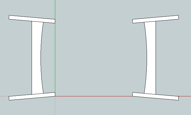
Below is a 2D output of the head/foot boards and so you understand the processes I have done I will explain.

I have created the legs as components then flipped the foot board ones on their red axis and the rigth hand side ones at both ends on their red axis.

Next I have used the protractor to rotate the legs outwards by 5 degrees and back by the same. So effectively the tops of the legs point out at a diagonal from the centre of the bed. Still with me...

Now look at the measurements (bearing in mind that at no point have I modified the squareness of the legs to each other)!!!

This is causing me an issue because now when I try to add the side rails and put the curve in them, because the adjoining sides of the side rail are not square it causes an issu.

Can you help??? :cry:

bed.jpg


Thanks in advance.

Id this explanation doesn't make sense let me know and I will try and make it clearer.
 
Doesn't make much sense!
Are you trying to splay the legs in 2 direction? Differences of 1.2 mm are not worth the bother - will be invisible.
 
TrimTheKing":2urs5xzb said:
Next I have used the protractor to rotate the legs outwards by 5 degrees and back by the same. So effectively the tops of the legs point out at a diagonal from the centre of the bed. Still with me...

Sorry not with you at all. If you have rotated the legs, I assume about a vertical axis, outwards and then back again. Why should the legs point out at a diagonal from the centre of the bed. If they are in fact pointed outwards then surely the dimensions will be different, inner surface to outer surface.

Trying to understand

xy
 
xy mosian":1k9joqwp said:
TrimTheKing":1k9joqwp said:
Next I have used the protractor to rotate the legs outwards by 5 degrees and back by the same. So effectively the tops of the legs point out at a diagonal from the centre of the bed. Still with me...

Sorry not with you at all. If you have rotated the legs, I assume about a vertical axis, outwards and then back again. Why should the legs point out at a diagonal from the centre of the bed. If they are in fact pointed outwards then surely the dimensions will be different, inner surface to outer surface.

Trying to understand

xy
Sorry, it was tough to write. Imagine the legs being vertical, looking at the footboard from the foot end of the bed. The lags cant out at 5deg so the gap is wider at the top than it is at the bottom.

Next I have also canted them towards you by 5 deg, I will do another pic now...
 
mr grimsdale":1qym7uxt said:
Doesn't make much sense!
Are you trying to splay the legs in 2 direction? Differences of 1.2 mm are not worth the bother - will be invisible.
I appreciate that in a build sense, but to make the side rails in sketchup the faces between the two ends don't match so you can't click the side rails into place and the model goes wonky.

The really weird bit is that if I can't the legs out from one perspective first them the the other then the discrepancy is between the short sides.. If I cant them the other way round then the discrepancy is between the long sides...

I am going to export some more pics to try and explain...
 
Ok! So the bounding rectangle at the leg tops is bigger allround than the bounding rectangle at the bottom of the legs? :)

Could this be done with the scale tool?

xy
 
Here we go, this is the end of the bed, the line is the vertical
bedend.jpg


And here's another view
bedend2.jpg


And here's from the side
bedside.jpg


And another
bedside2.jpg


Yep xy, your explanation was much better :D

Not sure about the scale tool, the bit I can't understand is why this discrepancy comes in because unless my mind has gone completely, what I have done should make no difference whatsoever to the squareness of the respective faces to each other...

The real problem is that when I draw the side rails in place, then add an arc to the bottom, because the face is slightly out of whack it won;t allow me to push the face of the arc through to the other side, it goes mental...
 
OK! I have managed to reproduce the effect. I think, bearing in mind I know nowt. That it is an axis problem. I am trying to align the axes with the long corner of a leg, but I've forgotten how. How about adding the curve detail, to the rails, before rotating the legs? Now you may have some extending of the rails to do once the rotation is done but that seems to work.

As for the difference in the dimensions. Well it would be nice to know what is causing it, but hey! this is wood perhaps the simple answer is to make it and put it together.

xy
 
As a last note. I have found, in my own bumbling way, that I have had most success drawing the parts as I would make them, then adding them to a model. In this case making a model of the rails and adding them as components to the assembly. Rotating as required.

xy shuffles off in the presence of a MASTER :) , but watches with great interest from the shadows.

xy
 
What happens if you chop the bottom of the legs off so they sit flat on the floor?

Oh, ignore me, I've misread the problem.

Oh maybe I haven't! Here:

bedend2.jpg


You can see the inner faces of the legs are "longer" than the outside faces, i.e. stick up further (in that orientation). As they are canted outwards, they travel further in the directions they are canted in, so the inner face corners will be further apart than the outer face corners.

I think.
 
I don't think this is SU, but rather your understanding of geometry.

Imagine the head and foot of the bed laid flat on the floor, it's clear that the inner corners of the tops of the legs will be further apart than the outer corners.

792567753_yHbkH-L.png
 
Mark, if you sent the file, I haven' seen it yet. Maybe the e-mail is being sent via surface mail?

Chris may have hit your problem on the head already.
 
Spot on, Chris.

Mark, to get your rails to behave, make them longer than necessary and then Intersect with Model. The ends will then match your legs correctly (after removing the waste, of course).
S
 
Dave - On baby duty so had to run away, just sent it now.

My brain isn't working, I've looked at both Jake's and Chris's explanations but it's not going in.

The faces of the legs that face each other down the length of the bed are square to each other so regardless of how long the corners are, providing they are the same at each end surely they will have the same distance between them over the length of the bed?

Sorry for being dumb here guys but it just doesn't seem to be logical to me :(
 
Scratch that last one, of course it makes sense that the longer ones will be further away because of the canting away from each other. They wouldn't if they were only canted outwards along the headboard but because of the double cant it does. That makes sense now :)

The bit I still don't understand though is why depending on which direction I cant the legs in first moves the discrepancy around???

Also, this shouldn;t make any difference to the rails being placed on the faces should it because the faces are the same length at the point in which I am trying to plant them?

Now I'm confusing myself even more!

I think Steve's explanation of drawing them too long and intersecting will be the answer but I'll wait for Dave's expert guidance.

Cheers all for helping.
 
Intersection and deletion of the unnecessary geometry will enable you to draw it but as you will appreciate the side connecting pieces would have to be cut with angled faces at their ends to fit precisely. Once you have drawn them, then of course you will have a component you can examine in isolation.
 
See if the following images help describe what you're seeing. I used 25° as the rotation angle for both directions.

First Rotation:
4372527949_7c7869cbb5_o.jpg


Second Rotation. Notice the black protractor.
4372527955_0a74b18f5e_o.jpg


The results of that second rotation. The horizontal guidelines are parallel to the green axis. Note where the top one comes out of the leg. This shows that the leg is indeed twisted relative to the axes.

4372527961_09fde082fc_o.jpg


If you make the second rotation about the green axis, thus:

4372527969_59c55b7e37_o.jpg


Then you won't get the twist. Notice the guideline. It lies on the face of the leg.

4372527973_e4e22ca153_o.jpg


In the shop, you would build the headboard or footboard laying flat with the legs splayed out. Then you would tilt the entire assembly. This would result in faces being oriented as you need them to be.

Or did I miss something?
 

Latest posts

Back
Top