Y versus Delta Wiring

UKworkshop.co.uk

Help Support UKworkshop.co.uk:

This site may earn a commission from merchant affiliate links, including eBay, Amazon, and others.

tool613

Established Member
Joined
4 Oct 2010
Messages
269
Reaction score
7
Location
Ottawa Canada
there is a question over at OWWM that does not seem to be getting an answer. I thought that because you guys have lots of delta motors you could enlighten us.

http://owwm.org/viewtopic.php?f=82&t=96065


"A friend of mine recently sent me an email with a question about a motor upgrade he is planning. I couldn't help him so I thought I'd pose the question here:

I recently fitted a VSD (single phase 240 V to 3 phase 240) to run a 3 phase 1/2 HP motor on my metal work lathe and it works great. I am so excited by this I have gone out and bought an ancient 1HP 3 phase motor and am thinking of replacing my single phase 1HP on my drill press with it.

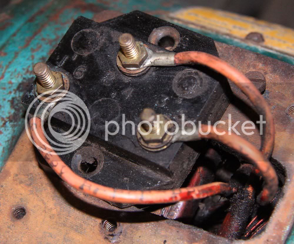
The problem I have is the VSD required a star or "Y" motor wiring and I cannot determine whether my motor is Y or Delta wired. All I have access to is the 3 terminals on the terminal block for the 3 phase wiring. I have managed to open the motor up, but the inside is a tangle of wires and I cannot see what is going where. The resistance is 19.2 ohms between all three contacts and there is no measurable resistance to the casing so the coils appear to be OK.

How do we tell if it is Y or Delta wired??"


jack
 
The motor should have a rating plate on the side. If so what voltage does it state? If it is 240v then it is delta and if 380/400v then it is star.

If the motor can be changed between the two then there will be at least 6 screw connectors in the conector box. The links between these connectors determine the mode.

Any chance of a photo of the connectors and plate ?
 
Jonzjob":6buo03qg said:
Any chance of a photo of the connectors and plate ?

this is all i have. it is wound 240 no motor tag!
IMG_0451s.jpg


jack
 
thanks Dave that is a good read. I really was hoping 9 finger would chime in on this one with a test you could do on the motor.

jack
 
Jonzjob":bhqcp5ek said:
The motor should have a rating plate on the side. If so what voltage does it state? If it is 240v then it is delta and if 380/400v then it is star.
.....


Are you sure about that Canada basic is 127V single 216V 3phase. or there abouts I believe.
 
CHJ
voltage in Canada is 120/240 single phase(.house hold) then we have 240/ 460 /600 delta(industry) you can get 4 wire star 480/277 and 208/120 3phase.
you boys don't have 240/3 there i believe ?

so for a VFD we feed 240 single to get 240/3. most US and Canadian dual voltage motors are 208/240/460 with the 208 and 240 being one winding.
most of the motor are y and it was my understanding that yours are mostly delta. is that true?

i really don't see what the problem would be running ether a delta or y motor on a VFD,but i am not smart enough to know.
you can see in the pics the insulation on the leads is marked 240.


jack
 
Whilst I have no practical experience of North American motors, I have seen a number of references to NEMA standard connections and these involve many more than three connections. So I assume this motor is too old to conform to NEMA standards.
US power distribution is different from the European system and I read about all sorts of voltages being found in Canada
A European motor with three connections would be delta wired and 440v but I don't know what would be regarded a the norm in US/Canada.

However, the first thing that strikes me is that no inverter I have seen specifies that the motor must be either Delta or Star. What MUST be correct is the output voltage of the inverter be the same as the running voltage of the motor - however configured.

Turning now to the resistance measurements, If we assume each winding is R ohms, then wired in delta, the resistance measured will be R in parallel with 2R which will be 2/3R. Wired in Star, the measurement will be 2R

If the motor is 1hp (how do we know if there is no plate??) then 19.2 ohms suggests to me that it is wired in star and so R= 9.6
If it were to be delta wired, it would imply the winding resistance would be 28.8 ohms which to me seems far too high of 1 hp motor unless it was designed to run on a much higher voltage.

Trying to move this forward, I would connect it to a 240v 3 phase inverter and use the inverter to measure the output current and see how this compares to the current that should be drawn by a 1hp motor.

I've not got a 1hp 3 phase motor to hand but later on I will go and measure the resistance of a 1.5 hp motor that I have in the workshop and add the result to this post.

hth

Bob


To reply to Jacks latest post

UK supply is 440v 3 phase in the street. Normally each dwelling has one phase of the 3 plus neutral giving 240 v single phase

Modern UK motors up to a few HP have 6 terminals so that they wired as 240 delta OR 440 star. Older motors have only three terminals and are always star 440v


Edit: I have realised that I have 3 phase 1hp motors on my lathe and mill!! These are delta wired and measure about 7 ohms so each winding is 10.5 ohms and designed to have 240 v across each.
Now comparing DC resistance is not a very accurate way of predicting AC performance but resistance does give us a relationship with the number of turns which in turn is related to the inductance and AC current/power developed.
If the mystery motor is star wound and 240volt, each winding should see 240/root3 volts =138v and comparing to my motor, each winding would be 10.5/root 3 ohms = about 6ohms each thus the terminal to terminal resistance would be around 12 ohms compared to the 19.2 quoted.
I conclude that the motor is possibly either designed for higher voltage or is less than 1hp

hth

Bob
 
Bob (9fingers) Once again you are very helpful. A real wealth of knowledge . I have forwarded the information and will post back any progress.
As for the VFD . i will see what kind it is and if it has a 4 wire connection.

jack
 
Are you sure it's not a single phase motor, that requires a split phase 3-wire supply of 120V—0—120V? Check that it does not have a starting capacitor and it's almost certainly three phase.

If your VSD requires a star connected winding, I guess it will need it because it has to be connected to the star point. Even if your motor is star connected, you do not have a connection to the star point.

There seems to be some misunderstandings about supply voltages. All European countries have adopted the CENELEC standard (the UK two decades ago) whereby the nominal voltage is 230V between phase and neutral. The voltage between phases is the phase - neutral voltage multiplied by the sqare root of 3, = 400V in Europe. Before 1990 the UK nominal voltage was 240 / 415V, most of Europe 220 / 380V. Some rural parts of the UK had a split phase 480V supply.

Canada's standard is CAN3-C235, USA ANSI C84.1. Nominal voltage is 120V single phase, hence 208V three phase, 240V split phase and, of course, higher for industry.
 
Looking at the photo you posted it looks like a label on the motor in the background at the top right - I wonder what it says. Even if it gives no information somebody may recognise the design of the label which could give more information on possible manufacturer etc. Ask your friend for a picture of the plate.

Misterfish
 

Latest posts

Back
Top