Tablesaw turntable

UKworkshop.co.uk

Help Support UKworkshop.co.uk:

This site may earn a commission from merchant affiliate links, including eBay, Amazon, and others.
hi mark


ordered 25 mm mdf today £17.50 for turn table arrives tomorrow afternoon , ordered 300 12.7 ball bearing yesterday on e bay just under £19 awaiting delivery hope they don't get held up in post strike. hc
 
head clansman":ce3xnjug said:
hi mark


ordered 25 mm mdf today £17.50

Wow that's cheap, must be standard MDF (?) or you've got a much cheaper source than me. I used moisture resisant for mine as I figured it's extra hardness would take the strain better.
 
hi mark

It's standard mdf , as my shed it bone dry, so not really worried about moisture , & 'i'm going to cut a third 18mm circle same dia to form the plinth underneath, the plinth being same size circle should remove any possible sag, the plinth will be leveled and secured first , then the first layer of the turntable screwed direct to that before assembly ,also thinking of having several locking points so it can be locked a a set degree for when i,m ripping long materials towards the door of workshop . mark is it possible to post a closer look at your locking point please . hc
 
hi olly


It was from G R B S Granby Roofing and Building Supplies here on the trading estate in weymouth . hc

ps um maybe i should say + 15% vat
 
head clansman":3ud1483n said:
hI

It's just arrived ,ooohh I forgotten just how heavy that 25mm MDF really is .hc

LOL - yes I had to get mine cut in half so I could shift it - MR is a bit heavier still I think, a real back-breaker even then.
I'll put the pics uplater this morning, but there's not much to see - just a hole drilled through both layers with an 8mm diameter rod stuck through. I drilled the holes after assembly for ease of alignment, so had to make sure the positions of the bearing runs were marked on the outer face as well so as not to hit them when drilling. Simple and not very elegant (I'm sure something foot operated could be rigged up without too much touble) but it works well enough.
 
As requested Martin here's the close-ups.

The pencil line indicates a point half way between the 2 bearing runs. I can drill new locking points anywhere along this line in safety.
DSC_0173.jpg


The "lock" is an old 8mm bolt I found in the scraps bin (I hardly ever throw stuff like this away, I have a feeling it was once one of the transit bolts from our last washing machine). I cut off the head and tidied up on the grinder and added a knob on the threaded end, but the bolt in its original state would have done just as good a job.
DSC_0176.jpg


I have a few optional locking points, just as you plan to. It's really handy sometimes to turn just enough to wring a couple more inches of outfeeed length. When I drill a new point I just extend the index mark down oto the lower section.
DSC_0177.jpg
 
hi mark


tis as i thought , i wasn't sure from the original pics if it was a marked on ink indicator or something you had let into the mdf surface , thanks for that , just waiting now for the ball bearing , oh and of course the new saw , but today had an email from suppliers, confirmed date is now not till 2nd dec :cry: .hc
 
It's not being delivered by the Royal London Hospital is it Martin? ;)
 
Hi

I have just picked up on this thread & you have solved a problem for me, many thanks. It really is simple but effective.

Can you please let me have some details of your dust extraction system.

Is it 50mm waste pipe? & what is the dust extractor.

Any help would be really appreciated.

Regards

Norman
 
hi norman


my dust extraction system is 110mm white pvc down water pipe and 50 mm waste water pipe combined with some home made 50mm blast gates and some larger 100mm bought plastic blast gates the extractor came from yandles it a record dx5000 twin motor work fine .

i designed my system so i could either use to 50mm or the 100mm separately from each other 50mm for light dust etc and 100mm for the saw and planer + bandsaw both system work independent of each other just by shutting one blast gate and both work fine . hope this is of some help to you . hc
 
hi WellsWood

I started my turntable two days ago and just finished it earlier today , " wow" that 1" MDF is bloody heavy to lugg about but it was well worth the effort, I can turn the saw with just one push of the finger and it glides round excellent .

Mark I just wanted to say thank you for posting this thread , it make life a lot easier now in the workshop . So tomorrow, connect up the dust extraction to the saw then that will be all finished as well . Now what's next ah yes tool cabinet and infill planes . hc
 
hi tom

ok sometime tomorrow although i haven't got that many pics maybe just enough to show how i cut the circles out on the band saw and the the jig i made up to routed out the gooves to take the ball bearing but i haven't got any pics of the grooves , its all assembled with the saw sat on it and believe me i ain't lifting that off again ooh it was a struggle with two of us to lift it off the floor . But hopefully it should be enough for you to get the general idea . .hc :)
 
Excellent Martin, so glad this has been of use to someone. Looking forward to the pics.

I'm surprised you cut the circles on the bandsaw, I did mine with a straight cutter in the router and the trammel that was later used for the bearing grooves. All done off the common centre point to keep it all nicely concentric - it also minimised the lifting, yep that 1" stuff weighs a bloody ton - getting the finished thing onto the floor off the bench was a little nerve racking, I certainly kept me toes out of the way 8-[
 
Hi all

ok here goes , basically as you know it all made from 25mm MDF , first rip the sheet in equal half across it’s width this gives you two pieces roughly 1.2m square turn one end over by folding end – end length ways and square up and line up the two machined cut edge’s .

First measure in 600mm from left hand machine edge along the front edge & repeat along top edge and mark a pencil line , now repeat 600mm up the left & right hand sides and mark a line , you have now divided the sheet into four 600 mm squares . This is then giving you the common centre point where the lines cross each other.

Next measure the foot print of the base of your saw. mine was 540mm across the front * 680mm in depth if my memory is correct , (adjust measurements for your own saw size), so now half these measurements , starting from your vertical centre line at the common centre point where the lines cross mark up 340mm and down 340mm and on the horizontal line mark 270 mm in both direction from the centre line , when line are drawn in, this is gave me the footprint size of my saw .

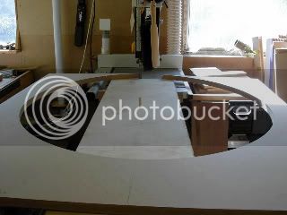
On my saw I have four feet 100mm Square * 30mm wide (L shaped) if you have something similar draw these onto the board as well (it’s important later) ok once you done that you need a large compass, or a set of trammels, measure about 25mm inside the inner edge of the four feet by about 25mm set trammels or compass and draw your first circle this is the first groove for your ball bearings now do the same about 60mm outside the corner of the feet and mark the second circle (second groove for ball bearings) , this now places your saw directly between the two grooves which will displace the weight evenly between the two ball bearing runs , right now strike you outer finish circumference from centre common point - to the left hand edge of the 1.2m square sheet and mark the circle , It’s important to do this I cut mine circumference on the band saw , it’s so simple, honest.

Ok so far.

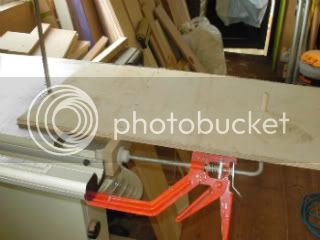
Now whilst both sheets are still together depending on what size dowel rod you have drill a hole of same diameter through both the sheets at the common centre point , this hole will first be used as the centre swivel point whilst cutting the out diameter on the band saw and whilst routing out your grooves for the ball bearings also now whilst the new circular base is still at the band saw remove the surplus off cuts from around it , (cut one sheet at a time NOT both together as they are much to heavy to handle for safety reason) when both circles have been cut the centre common point will need to be drilled larger 12.7 ish or there a bout’s to accommodate the bolt to bolt the two section together which you’ll need to chop the hexagon head flush into the underside surface before the lower circle is secured to workshop floor first before final assemble .

MAKING THE JIGS TO CUT THE CIRCLES

1ST JIG

You’ll only need scrape timber don’t use any thing expensive. Find something wide enough to balance a half sheet of 25mm MDF on it only need to be about 300mm. I think at this time I let the picture explain how it’s done quite simple really. Jig clamped to bandsaw. Photo showing centre swivel pin. That’s your first jig done.

PDR_2345-1.jpg


CUTTING THE CIRCLE

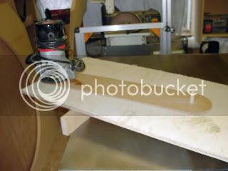
Ok, all I can show you here because I didn’t take any photos of the circle being cut but what I can show is the waste material left in position which I think you’ll get the idea how it is done , with the half sheet in position with the end of sheet resting against the band saw blade and the centre common swivel dowel through the hole you previously drilled in your half sheet of MDF when machine is running just feed the sheet through your hands from right hand to left hand with a steady flow of movement your band saw will cope with the full circle easily , I used a ¾” blade with no problems at all , there as I said simple, any way a photo.

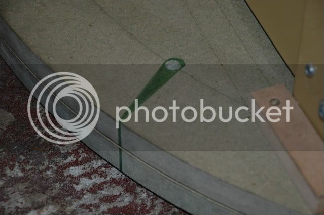
Please bear in mind this photo was taken as a mock up for this post only normally the blade height would not be set that high up when in use. Now repeat again for second circle.

PDR_2394.jpg


2nd JIG.

Ok again just scrape wood In this case I used hardboard only because that’s all I had.

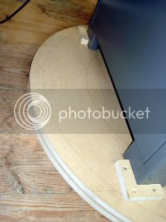
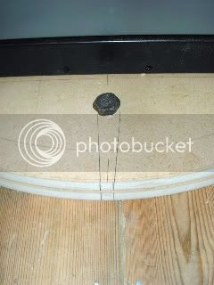
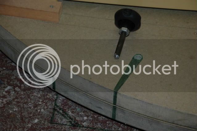
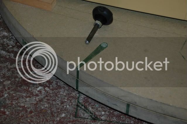
Remember this Photo is also a mock up for this thread only. Here I’m sorry you have to use your imagination that the circle of MDF is there the swivel dowel is in the inner hole to cut the inside groove for the ball bearings , the other hole you see if for the second groove for the ball bearing. Once you cut the two grooves into both circle your now ready to start assemble, (but don’t forget to enlarge the centre common hole to take your centre bolt and also cut the hexagon bolt head into the underside of the bottom circle), do that and then secure bottom circle to the workshop floor (hope your floor is level) if not you know what to do .

PDR_2346-1.jpg


BALL BEARINGS
Ok so now the bottom circle is secured to the floor , I used 12.7mm ball bearing with the grooves cut to about 5.5mm in depth on both circles this left a space between the two surfaces of about nearly 2mm ( now you need a 2mm washer slip it over the centre bolt roll all ball bearing into the grooves, I bought 250 in all which to be honest wasn’t quite enough, so buy about 300 in all this should leave just a few over , but don’t do what happened to me when opening the box the inner plastic bag split open and yep all over the workshop floor, oh pipper it took hour finding them all , What joy. Now slip on the top circle and the set of grooves will mate up with the ball bearing and gentle tighten down the centre bolt , there you go it’s ready to lift and position your saw to it .

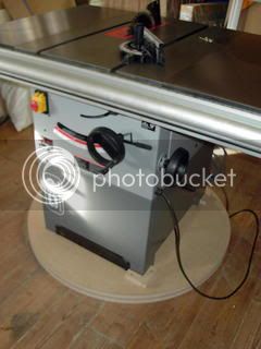
This shows the legs of saw sat between the two ball bearing grooves

PDR_2349-1.jpg


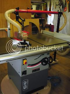
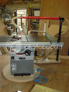
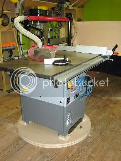
finally the turntable still not yet finished or secure more to follow as soon as possible .

PDR_2373.jpg


hc
 
hi guys

nearly there , been a bit brighter today so managed some time in the workshop working on the turntable . One of the reasons it's taken some time to finish is now it's mounted on the turntable is when i turn the saw i wanted the extraction to turn with it which it now doe's only a few minor things to finish to get it completed , things like a couple of fittings to reduce down from one pipe size to another size on the extraction as shown in pics , i order a couple of roller ball bearings as well , oh and apply a second coat of wax to the machine beds as well .

this pic show saw in its normal position facing across the workshop with over head extraction

PDR_2402.jpg


Pic show saw turned about 40 degrees to the right so if i want to cut long length of timber open the workshop door and feed timber out through the opening.

PDR_2403.jpg


this one is when it's turned 90 degrees to the left placing it now length ways down the shop so I can eventually use it as a gross cut saw, & router station, but that's another thread later.

PDR_2404.jpg


this pic shows missing connection and the arm that supports the the over head extraction piping which is screwed to the turntable, directly under the stanchion poll I fixed an old chair caster (temp) two new roller balls bearings were ordered today to go under there so when turned it just swing round with the saw .

PDR_2397.jpg


this one showing electric's, plugged at both end, so i can disconnect which ever end i like and it move round with the turntable .

PDR_2399.jpg


last pic showing locking devise just an old bolt i had lying around placed in a drilled hole right through into the floor below pull out swing the saw where you want it redrill hole place bolt into and it's safely locks into position .

PDR_2401.jpg


still a little more to come so stay tuned . :wink:
 
Back
Top