Questions about metal shoulder plane build

UKworkshop.co.uk

Help Support UKworkshop.co.uk:

This site may earn a commission from merchant affiliate links, including eBay, Amazon, and others.

Ttrees

Iroko loco!
Joined
18 Nov 2012
Messages
4,927
Reaction score
926
Location
In me workshop
Hello folks
Got the chance to do a bit of metalwork for the next few days, and I fancy making a start at a shoulder plane build.
I'm thinking something along the lines of the older Preston ones that use a wooden wedge.

I think I will use regular mild steel plate, as I probably have something thicker than, say 4mm(ish)
stock which I will be using for the sides.
I am going to dovetail the sides but I see some other things that look like they could be welded.
Has anyone hade a WIP on this ?

I am curious on traditional construction of this kind of plane, and have a few questions
The early Preston and similiar seem to be cast, but I have seen the term gunmetal used often...
Point I'm getting at (badly) is.... there must be the handmade way for making it in the same style...

I was hoping Bill Carter would make some videos on using mild steel for planes, before I got around to it....
as I have a few planes in mind
Maybe someone could give me some info, or links on the topic, or point me in the right direction for the questions I have.

Dovetail angle... guessing its a 1 in .... (fill in blank)
Recommended thickness of sole using mild steel, and at what bedding angle?
The ends of the plane... are they dovetailed into the sides, welded, or both?...
Come to think about it, are the dovetailed sides welded too?

What about the connecting piece the wedge bears against... guessing this is dovetailed into the sides?

I have other questions about peining ...
Is it a regular drilled hole or is there a small countersink for the mushrooming ?
What metal to use for the job, where to get it easily, do I need a blowtorch?

Thanks
Sorry about the amount of questions
Tom
 
Watching some youtube videos on plane construction by novices so far, has infulenced me on the following...
Not to have very steeply angled dovetails, as it looks tricky to get into the corners and making a nice job.

And the fact there seems to be no need for end caps on the plane, if treated gently
This looks like it might take some time otherwise.

Still in the dark about the proper materials, and which way to pein the connecting "pins" if thats the proper word

Tom
 
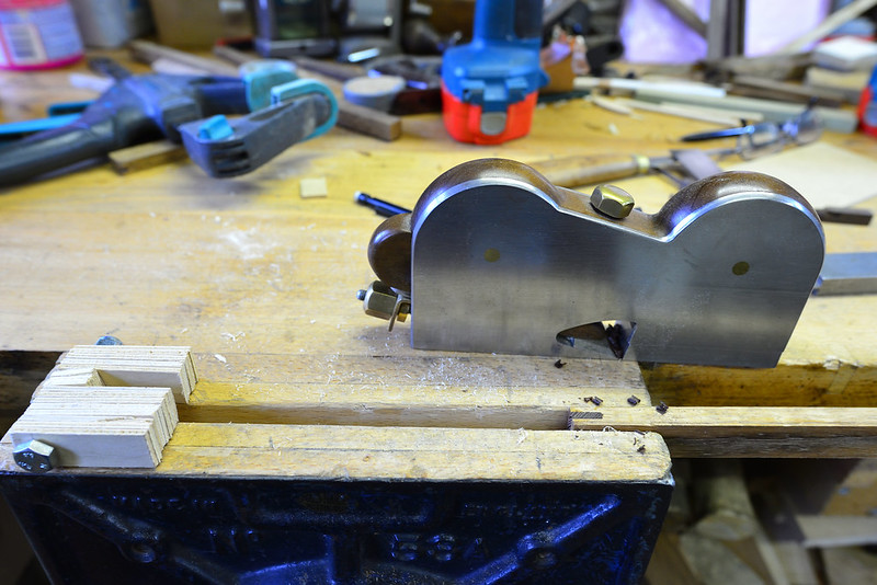
I made a very simple shoulder plane from mild steel. I riveted it together.
Pictures here

another-home-made-shoulder-plane-t26321.html

It's not the prettiest but it works well.

If I did one now I would use a shallow tapered reamer to enlarge the holes, rather than an ordinary countersink, but the construction method is sound.
 
Hello again
Looking at some more designs since in the same pattern as the Preston...

There is some stuff needed to make a really good plane properly...
I thought I could get away with just the hard work part #-o

I dont think I would be able to drill with the inaccurate pillar drill in the metalshop...
I have a solid one in the woodshop, but thats not close by.
Although this project may take longer than I'd like, so I may consider that yet..

Looking at a gunmetal shoulder plane by Spiers which has peined dovetails, so it cant be taken apart.
I was originally aiming to not have to do any peining for a few reasons, but this has made me think again for future projects...

I have at least decided, that I dont like the look of the dovetails which are not splayed enough, so the dovetail square
'one in seven IIRC, is not going to be used.
I have brought the protractor and the sliding bevel aswell, as it looks like most are at the angle of a trianglular file @ 60 deg it looks.

It seems I should consider getting some annealed stock for the pins
Is there any HACK way I could find or make some annealed round stock?

I maybe able to get away with filing instead of getting a reamer for the job, as counter sinking bits seems not to be the tool for the job.
I might try finding out what angle the blade is bedded at, when I need a cuppa

It seems like the Veritas medium sized shoulder plane is the preffered size, I might make this plane to those dimentions...

I have no blade for this yet, and toying with the idea of welding a chisel to some mild steel or something similiar

Thanks for reading
Tom
 
IMG_2050.jpg
Back again with some more research done
I found a fellow on Youtube called Young Je, he is peining dovetails in the start of this video
https://www.youtube.com/watch?v=5jIlmRwx5z4
He is doing this to rolled steel without any annealing needed, and it looks, dare I say....achieveable.

On the design matter at least I've got some hints what to shoot for on the bedding angle for the iron...
It seems the Clifton which I have read designed on a later Preston with a lever cap is bedded at 18.5 degrees.
The Lie-Nielsen at 18 and the Veritas at a 15 degrees.

I will go with either 18 or 18.5, unless I can find out that these older Preston versions are bedded at something else.
David Barron has made a nice post on this plane made by George Miller in the Spiers style.
His post is makes me want to copy the design
I havent decided on length, but it seems most are about 11/16" wide, so thats what I'm shooting for at the minute.
Looking up George Miller shoulder planes, suggests that planes in this style seem to be well in the inch and over...
That's not to say there's no reason to make one slimmer, right? :)

On the end caps or whatever you should call them, I'm still in the dark on that one.

Thanks for reading
Tom
 

Attachments

  • IMG_2050.jpg
    IMG_2050.jpg
    153.9 KB
Tom
For the blade you will need O1 steel easily obtainable form eBay Cromwell tools etc.
Welding a chisel to some bar won't work.

You need to make sure you have clearance to insert the blade down the throat of the plane, this is one reason the blades are chamfered at the sides.

Pete
 
Thanks Pete
I still may try to weld a chisel though, as I'm doing things on the cheap.
To be honest, I thought I was going to be looking for the most firmer of style chisels, so thanks for clearing that up for me.

Tom
 
Ttrees":2on39h6t said:
Thanks Pete
I still may try to weld a chisel though, as I'm doing things on the cheap.
To be honest, I thought I was going to be looking for the most firmer of style chisels, so thanks for clearing that up for me.

Tom

Find an old blade that's about what you want or buy O1 stock and use it. It'll be cheaper than a good chisel when all is said and done, and much more predictable (plus, it won't be tapered in the wrong direction like a lot of chisels are). A shoulder plane should have about $5 worth of O1 steel in the iron, and the blade will be small enough to heat treat with anything (and you can use used motor oil as the quench if you're really tight - just be aware that your oven will smell like used motor oil if you temper it in an oven. You can temper over a flame, but it's not quite as reliable when you're starting out).
 
I dont have the knowledge, nor the money to easily make up a heat treating setup I don't think.
And I dont have an oven either :(
Must get that fixed, as I have some HDPE to melt ...
On a more sensible note

I take it from what you are saying, that the iron needs to be parallel in thickness or thicker at the buisness end
This makes an interesting topic, as a recent shoulder plane thread I read, someone has made a shoulder plane in the
style I want to try, but using a screw instead of a wedge, a screw activated wedge if you will, because he didn't like the
amount of whacking needed to release the wedge
I wonder if having a taper will affect the holding power of the wedge?.

I'm sure some folks notice this, like the molding plane guys who collect the same makers.

At the moment I'm more concerned on the design and making a start on the dovetails, since I have a chance to
do some metalwork.
I have no immediate use for this tool, but its on the tool list of things to make
along with a router plane, possibly shooting plane, and some miniture planes maybe also.

Looking at a Rob Cosman video, he uses a Lie-nielsen skew block plane with fence to mark out dovetails
It creates a ledge the thickness of the pin board so it sits flush for a more solid registration when marking out.
This looks like another project for fun.

Thanks for your input guys
Tom
 
A screw to hold the wedge like this

Triming feathers by Pete Maddex, on Flickr

It works well but you need to put a point on the screw and a hole for it to locate in, or as you adjust the blade the wedge moves.

If you make a blade I will harden and temper it for you.

Pete
 
Thanks for your very generous offer Pete, but I live in another country.
Cant wait to make a start on this

Tom
 
Adjustment of any plane with a wedge and iron is easier if the iron is tapered. If it's not, then you need to be able to strike the wedge sometimes to get the iron and wedge loose, plus the wedge has to be very tight to keep the iron from retracting during a cut.

As mentioned, a screw or cap should be used for any parallel irons if you have a choice, but you can get away with a parallel iron on a shoulder plane because you're not going to be doing a whole bunch of taking it apart and putting it back together. Any heavy work should precede use of it.
 
Hi again
I only really got started this morning as I had to find plate big enough, and luckily I found some 4mm
plate, so I didn't have to make this out of that big 8mm plate, and grind it down :shock:
This plane is going to be 11/16" wide, so the thicker steel would have made too skinny an infil/wedge.
It would probably present clearence problems getting that iron flipped over to sit on the bed ,
I wonder if anyone relieved that area on any kind of plane? ...not happening on this one, so I'll try and stick to
the thread.
The thicker 8mm stock is for the sole.
Those 5" thin cutting discs from Aldi are useless, messy, and inaccurate, the regular cheapo slightly thinner discs are way way better.
Thats most of the messy part done, and something to do now in the metalwork shed.

I dont think I'm going to file another dovetail angle to the bottom, and pein the second set of dovetails, as it seems they will be solid.
I still have to see a good demonstration of that, because it seems a bit of an art to me.
I never had a tree trunk and a block of steel to pound on before though :D

Does anyone know the traditional way the bridge above the wedge is constructed on dovetail planes ?

Specs on the plane, at least the way I hope it turns out
George Miller inspired plane with some changes...I drew the best representation I could, with the changes I made,
which were...
Reducing it one inch in length.
Reducing its height by 1/8"
Reducing it to 11/16" in width.
Reducing the bed angle from 20 to 18.5 degrees.

Thanks for reading folks
Tom
 

Attachments

  • SAM_2640.JPG
    SAM_2640.JPG
    219.2 KB
  • SAM_2635.JPG
    SAM_2635.JPG
    238.7 KB
Hello again, been doing some more on this
Sourced some irons from two woodies which are in a bad way, been outside in the elements for who knows how long.
I think I'll use this one, anyone have an idea of the maker?
1.jpg


Got started cutting the dovetails, not so easy in steel compared to bronze I found out :)
2.jpg


Found out the angle I wanted for the dovetails, which is one in four
3.jpg

4.jpg


More cutting for the sole
5.jpg


A shot of the tools used so far, I really like this Britool hacksaw :)
6.jpg


This cold chisel business doesn't really work like it does with bronze
7.jpg

Found it was a whole lot easier to just saw them off :)
8.jpg


I would love to have some decent flat files for the job, as the ones I have are all higgledy piggledy (hammer)
Luckily I have this flat block to save the day :D
9.jpg


The fit is getting close, I should have had used dividers for the job, but they're elsewhere
and I should have brought the bench grinder into the shed sooner for grinding plenty of scribes from steel nails #-o
10.jpg


Have yet to repeat this on the other side of the the sole using the same method
Kind of winging it and it it could still all end in disaster
Only one way to find out

Thanks for reading
Tom
 

Attachments

  • 1.jpg
    1.jpg
    371.1 KB
  • 2.jpg
    2.jpg
    188.6 KB
  • 3.jpg
    3.jpg
    176.4 KB
  • 5.jpg
    5.jpg
    186.5 KB
  • 4.jpg
    4.jpg
    195.4 KB
  • 6.jpg
    6.jpg
    194.3 KB
  • 7.jpg
    7.jpg
    201.5 KB
  • 8.jpg
    8.jpg
    185.3 KB
  • 9.jpg
    9.jpg
    188.8 KB
  • 10.jpg
    10.jpg
    196.8 KB
Looking good!
That iron is marked Thomas Ibbotson, an old name acquired by Marples in 1905. Marples were very flexible as to the marks they put on their products.
 
Thanks for saving me hours of searching for the maker of this iron AndyT :D
On a bit of thread de-railment, I wonder if this iron has enough good steel left as its really badly corroded...

I would have thought that all these thick old irons had a good thickness of laminated hard steel on a softer substrate,
but watching a recent video from Bill Carter Restoring a Towell mitre plane https://www.youtube.com/watch?v=wzDd-OBrw0A
at 5:05 into the video, he mentions he swapped the iron out because the old iron had worn right down to soft metal :shock:
Is what he's referring to, a blade whats ground past the welded laminate, or lapped through the laminate because of say corrosion,
or some other scenario?

What I'm getting at is ...
I'm guessing that the hard steel is only on, say an inch or a wee bit more of the business end of the cutter, and the rest of the iron
above this, soft metal, so I have to try and get the shape of the shoulder plane iron from this business end only?
And if so....
Is there much differences in the thickness of the harder laminate in makers, or periods of the time, as if the corrosion is really bad
on this iron, I may have to dodge the worser bits, along with dodging the cap iron slot, so may have to cut into the iron diagonally
to get the shape I want with the good stuff/lesser corroded areas.

I suppose the best bet, and least destructive, is to grind the bevel to try and determine how thick this laminate is, and hope it doesn't get super thin as the iron tapers thinner further up.
I have another old corroded iron to see if it has a thicker hard metal laminate, but not with me at the moment.

Thanks for any input on this subject, which probably deserves a thread of its own
Happy to hear anything on the subject
Cheers
Tom
 
Ttrees":28s9nh7n said:
What I'm getting at is ...
I'm guessing that the hard steel is only on, say an inch or a wee bit more of the business end of the cutter, and the rest of the iron
above this, soft metal, so I have to try and get the shape of the shoulder plane iron from this business end only?
And if so....
Is there much differences in the thickness of the harder laminate in makers, or periods of the time, as if the corrosion is really bad
on this iron, I may have to dodge the worser bits, along with dodging the cap iron slot, so may have to cut into the iron diagonally
to get the shape I want with the good stuff/lesser corroded areas.

I think the length and thickness of the hard steel bit will vary slightly from cutter to cutter as it was all done by hand on the older tapered cutters - the ones I have seen all have a rather thin laminate, which I suppose was desirable as it saved on materials costs while maximising the life of the tool and minimising sharpening effort.

at one point we had a discussion on the forum how best to see where the lamination stopped and started (on thin stanley and record cutters as it happens, but the same principle applies) and grinding the bevel was one of the methods recommended.

looking forward to the future instalments!

PS A good video on the forging to make a laminated tool (a chisel in this case) is here :
http://www.pbs.org/video/2365386383
 
Back
Top