North bros 1003 bench drill - dismantling?

UKworkshop.co.uk

Help Support UKworkshop.co.uk:

This site may earn a commission from merchant affiliate links, including eBay, Amazon, and others.

nabs

Established Member
Joined
24 Aug 2015
Messages
1,456
Reaction score
16
Location
Herts
Hello all,

I bought a rather sorry looking example of this bench drill from ebay - it was very rusted and all of the moving parts were seized and I am slowly making progress dismantling it.

I got a lot of help from Rhyolith's article on the same model, which shows a partially dismantled example, but I am stuck (literally) on a couple of parts.
http://www.timetestedtools.net/2016/08/30/north-brothers-yankee-no-1003/
Despite my general lack of mechanical sympathy I am afraid that if I keep up with my current levels of "persuasion" without understanding how the remaining parts go together then I will break something.

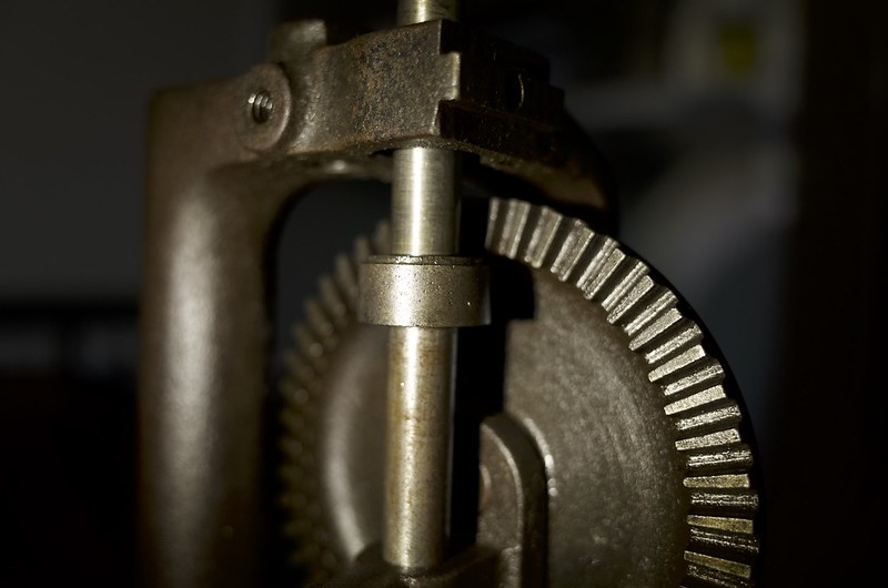
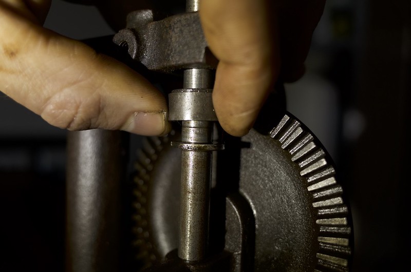
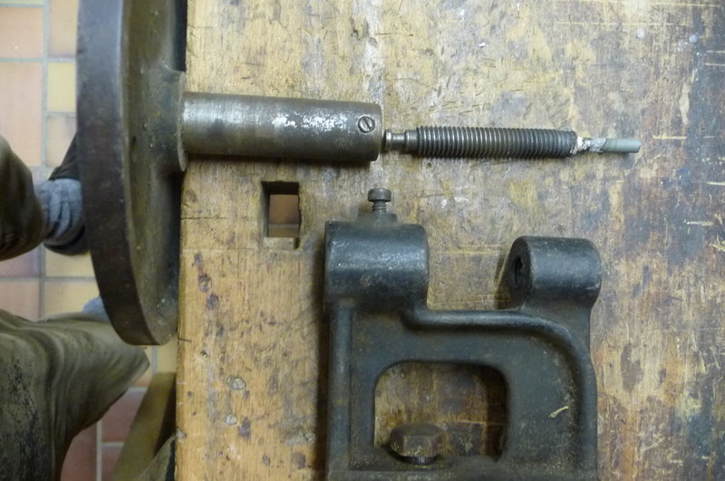
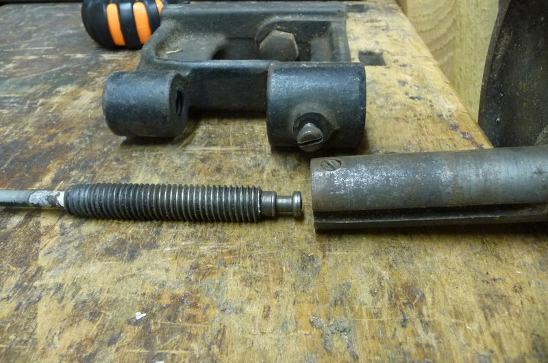
Here is the first part I am stuck with - any tips gladly appreciated!

Y1PMDipYfQYuRRogdi1E53xyL_jahnITkFy0gImtDrQuGAhUDciSyw


I was able to get the table from the main drill body without too much trouble, but I am not sure what to do next. I have degunged the wheel and screw that controls the height of the table and it now moves, but I can't lower it more than 1/2 cm before it stopped by something - I wonder if it is attached to the upper part somehow?

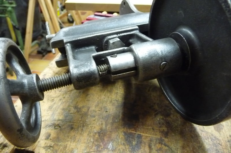
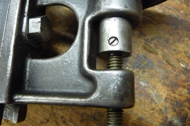
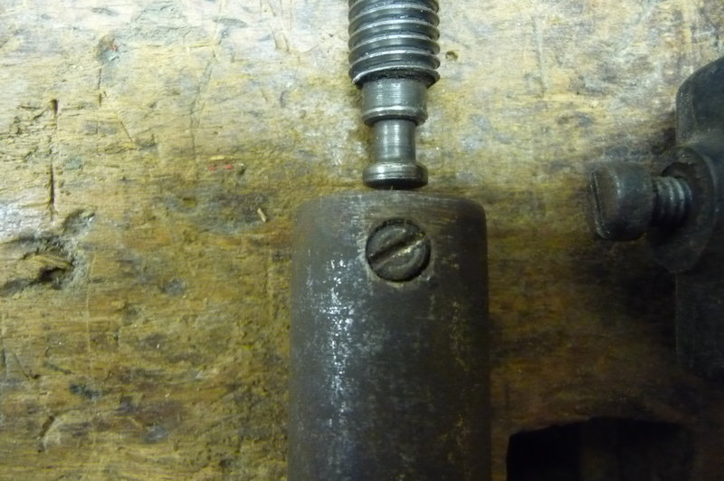
The table is stuck fast - I found an old ad where the grub screw is shown protruding so I guess this locks the table in place. Any suggestions on how to remove the grub screw? it too is stuck fast.

cheers
Nick


hCQ65BzF-M5s76W81QVnNACArT9JXOdnrvLvkBn5L47MmI87ZlN-wQ

4-E5D8CX19praDqDb3V5UISQ7Ym9hdp0veeRtyoTJpRUGBwodHizOg
 
I wonder if what you're experiencing is part of the threading that was exposed and damaged by rusting getting stuck once it gets to the internal threading? This is a common problem with rusted threads in all sorts of situations.
 
If I can understand the pictures right (not having the real thing) I think the set screw shown in your photo would sit in a groove, turned on the end of the threaded rod. This lets the threaded rod (which does rotate) move the upper cylinder up or down, without rotating it. It can't rotate, as the other set screw (as seen in the ad) sits in the long groove.

With the first grubscrew, it would almost certainly have had some thread locking compound on it when it was assembled. It would be set right, and not need to be adjusted. The compound would stop it working loose by vibration.

I don't know how you would free it from the compound, but I guess either a solvent (acetone?) or heat. (Not at the same time, most solvents burn very easily!)

Maybe the same would apply to the other screw too.

So I would try gentle heat, from a hot air gun or plumber's torch.
 
To dismantle the table.
The grub screw at the front, will NOT come out at this stage. It has a square tip that rides in the slot to prevent the table rotating.
The top of the table has a hole, in there, I expect is a screw/bolt/Allen head, this needs to be undone, the table will now lift out, releasing a number of small ball bearings! Don't lose them.
The lower grub screw is a depth stop on the thread, this may have damaged the thread. Hopefully now the wheel will unwind out.
On reassembly the bolt through the table shouldn't be tight, but has to rotate with the wheel, whilst the table is fixed.
The idea is very similar to the Union Drill Quill mechanism, that uses lock nuts to control the slack.
Your 5mm movement may be this slack.

Bod (who hopes he right!)
 
thank you both - I will have another go at the weekend and report back!
 
Nick,

There are family members who call me a drill-addict -- don't know why ...

Anyway, I have both of these nice Yankees, the small #1003 and the larger #1005.

This is the 1003:
You must remove both grub screws, one connects the screw of the handwheel with the table, the other one prevents the table from turning around with the handwheel.
28047495tu.jpg


28047499eo.jpg


This is from the 1005 (which is under restoration) to show the inside (ignore the missing handwheel):

28047502su.jpg


28047507dy.jpg


28047510ly.jpg


Soak the grub screws in WD40 or some other oil, to loosen the gunk and rust, then they should move.

Good luck

Claus

PS: I'm from Germany and my English is a bit rusted too, so excuse any verbal/linguistic faults please.
 
Ah, forgot:

There is NO Allen or other screw in the table top, and there ist NO ball bearing anywhere at the table unit. So just go ahead, nothing can go wrong.

Claus
 
many thanks Claus for the clear explanation and the pictures - it is very helpful indeed.

I must say that the drill seems to be very well made, and I am looking forward to getting it working again.

I'll report back on progress shortly!
 
It must be well made to be 'absolutely accident proof', gotta love old advertising material!
 
success! In the end a bit of gentle heat from a hair dryer (thanks Andy) was enough to start the small grub screw moving.

I slightly marred the slot getting it started but I was able to remove it by applying firm pressure and very gradually turning the screwdriver.

Thanks for all the tips so far - here are my next two daft questions!

I see from ryholith's pic of a partly dismantled 1003 that the part highlighted in red below is sort of a fat circlip with a ball bearing race on top of it (quite possibly these are not the correct technical terms!).

I think this is the bit he is referring to in his article when he says:
Firstly there is a spring mounted ball bearing mounted on the main spindle that fits into a notch inside the down-feed thread, thus driving the down-feed. The bearing comes to of the notch if the strain exceeds a certain level. It kicks in if the down-feed reaches the limit of its travel and also works as part of the automatic ratchet feed
https://flic.kr/p/LcAFkj
.. but I don't understand what it means to be "spring mounted"
How do you think it should be removed ?


Finally, I can't figure out how to remove the handle, although I am sure it should be simple!

Thanks in advance for any pointers...

success:
jxVeolSD_UTw-5Ye_rkXHPlL9al0DKAR2JzwbHtuBVRM6_yDgC2Hbg


ball bearing bit:

FqXWFNE1dvUnWyvF9brdvP65GKMrbodWvMuBNPyJhZLnQbzJEAF9Ug


handle:

bBf3KnDk9S1-JlzWHVbB9R3q9HYV8aU9SkLY6IA39LrwuwhpyVNeRA
 
The spring mounted ball bearing is literally just a ball bearing in a hole with a spring behind it. I have no idea how to remove it though... if the purpose for doing so is cleaning then a but of white spirt and a nylon brush will probably do the job without removing the bearing.

I have never been able to remove the handle or the drive gear on mine. As its clean and working I have never bothered putting a lot of effort into it (or risk of braking something).

These are one of my all time favourite little machines, you won't be disappointed with a working example :) Got mine here if there is anything specific you want to know. Also feedback of that article is useful, I will clear up that bit about the bearing (and the numerous other typos I have not spotted!).
 
ah - I see I did not read your original article properly and we are describing different parts. I must have missed the spring loaded ball bearing when looking at the main spindle. In fact it is the main spindle I would like to remove, but I am not sure how to take off the part highlighted with a red rectangle in my post above - do I just pry the top off so I can get to the "fat circlip"?
 
thanks Rhyolith for the clarification - having cleaned some of the grunge from the spindle I can see the spring loaded ball bearing you were describing. I included a section of your dismantled drill picture to show the bit i am trying to remove - any suggestion from you, Claus or others would be appreciated.

B55ixUFwt02DLfwt1JJEsXi836qPLIF9kRw0RkouHTUyZ36hyuTK8Q


In the meantime I've cleaned all the parts I could remove and reassembled the table. It is testament to how well made the drill is that, despite the fact that it took so much twisting and bashing to remove the seized table from its housing that I feared it would break before it freed up, with a quick rub down using sandpaper and wire wool and it now works as if it were made yesterday.

I also managed to take apart the chuck which required a fair bit of leverage (thanks again to the mighty Record Imp!). It is a very clever design - similar to the spring loaded 3 jaw chuck you find in some old miller falls hand drills, but with the addition of slots in the carrier that receive the 3 jaws and stop them moving from side to side. There is a patent date just about legible on the chuck that says Mar-15-10 - this is a reference to US952320 applied for on March 15th 1910 (see diagram below).

the chuck was very rusty inside, so I used some wire wool stuck to the end of a suitable bit of rod to polish the jaws - a quick rub down of the jaws and it works perfectly. Not bad when you think it is at least 80 years old, and appears to have spent some of it's life underwater!

cheers

Nick
cleaned parts:

5UccDdXfrWL7hgpaLD8P3p2WXRrP65x09pT8xbjfBfAA_paZUsAEHA


mighty imp:

ZWSgz9JRsKJDB5II5nklU1lt6TIh1x3B1uV14HNKUirDcztKfSPaWg


chucks (north bros on the left):

VmW_Gyf0vtxGin5NB5N6ppqDZEOX-_eSDp9f4kLY1lpAcRHOx4YLwQ


patent:

K73gNJ3txXrzEae0dWOyouwQq9M6tAn9NQsiI27pwYzH5flESasfpA
 
Ah ok, the spindle. I will try and remember here, its been a while since I last dismantled it.

I think it comes out downward (toward where the chuck is). The only thing that stops you just pulling it out is that C shaped washer, which is inside the thing the ball bearing rides on (ball bearing bit you have the red square round above). to get it out you just slide the ball bearing bit up the spindle, it should leave the C washer there if my memory serves. The you just remove the C washer and the thing slides out.

If that does not work I can dismantle mine to remind myself exactly what is what.
 
Thanks Rhyolith, that makes perfect sense - I have reassembled the drill and now notice there is a gap between the base of the main thread and the housing holding the ball bearings. The only explanation I can think of is that the housing and c-washer have somehow been knocked down the spindle (and perhaps the top edge has been caught in the slot intended for the c-washer such that it prevents me moving the housing upwards?)

I shall have a closer look tomorrow.

I did have 5 mins trying out the drill and was puzzled to find that the lever for switching the drill between "friction" and "ratchet" mode made no disernable difference no matter what direction it was pointing. Now I look at the pictures on the computer I can see that I have got the part that holds the lever upside down, which might explain it!

The mechanism seems quite sophisticated and, assuming I can figure out how it works, I will report back with an explanation and an action packed video. I hope you are all able to contain your excitement - I may be some time!

Nick

gap:

nebnbrGlCtWqykaIaaILmf8uO3hDGB353fOqoJl3Ae2qvtFFmhnu2Q


thrills to come:

8O0yXwA-s17fRpCfAA4YZiDgGupTCMBHjqpZAuyvnACLfJLqG8jNhQ
 
The mechanism is sophisticated, its takes a few times taking apart and using it to understand I think. Its possibly the best auto-feed mechanism for a hand powered drill anywhere (that I have tried) though :)

I take it you still have not been able to remove the spindle? This might help:

North Brothers "Yankee" No.1003 (bearing) by Rhyolith, on Flickr
North Brothers "Yankee" No.1003 (bearing C-clip) by Rhyolith, on Flickr

So thats with the down-feed thread removed (like in your last photo above) and the spindle dropped down about 1". The Bearing casing is lifted upward (toward the top of the drill) with ease, revealing the C-clip thing, you can see this in the second of those pictures. Once the C clip is gone the whole thing should just slide out downward.


I have also been editing the article based on this so it will hopefully be more useful, like re-wording the bit about the bearing in the spindle and adding pictures of that bit. Any more thoughts on the improvements and the article in general would be appreciated :) (like things being clear enough etc). http://www.timetestedtools.net/2016/08/ ... e-no-1003/
 
Thanks - I am indeed still stuck and it is very kind of you to take those extra pictures.

It is good to know that the housing is supposed to separate easily from the C-washer, since it confirms that somehow mine has been damaged (although the housing spins reasonably freely and independently of the spindle and the C-washer, I simply can't lift it off the washer). My theory about the c-washer having jumped out of the groove was wrong, as when I looked closely I can see it is located in the groove and spins freely.

It is all a little mysterious - the main down feed thread does not reach the top of the bearing casing and this creates around 2mm of play in the mechanism (see pic 1). I can't figure out why though - one (implausible) theory I had was that the small rod that fits in the spindle to drive the eccentric cam had worn shorter allowing the spindle to sit lower than normal in the frame (see second pic below where the original rod is installed)

With the benefit of hindsight this is a daft theory, but before that occurred to me I had cut a new (slightly longer) rod as a replacement. This had the desired effect and lifted the spindle higher and closed the gap between it and the down feed thread, but of course it meant that the screw and washer at the top of the drill was now 2 mm too high and no longer held the ratchet mechanism to the drill body so they would now move up and down and jam. Doh!

So by a process of elimination I concluded the only other explanations must be:
A) the spindle has stretched (!)
B) the housing has somehow been crushed on to the C-washer

Out of the two, B) seemed more likely so it was most disappointing to see your close up picture showed that your part was identical to mine - I had hopped the casing would be somehow sat on top of the C-washer where mine had been forced down on top (which would explain the gap and perhaps why mine was stuck), but sadly not. Arrrrrrrggghh!

I think I may have to just keep applying more force until the housing comes off, but I already chipped a small part from the housing doing just that. Having said that, the drill is not useable at the moment so perhaps I will persevere and then be on the lookout for something I can fashion in to a replacement bearing housing if (when!) it finally breaks/deforms.

I shall leave it to the weekend to see if I have any better ideas in the meantime. Thanks again for the help so far and I will take a look at the updated article!

gap:

NtdgFj1sZXiIyS2cNDRG9pJKRSCNNnq_ELx0aETITiqofBtBEaWl4g


rod:

X0VXp_0YL66JsauY6ylbBjb1xUzPxE6uTwp_Wlol7e6h62MSl5ET0w
 
Could you take some pic's looking up under the bearing casing so I can see the C washer?

Does can the c washer rotate indepentantly of the bearing housing? (I am thinking thry may have fused).
 
so...

the housing is definitely free of the c-washer, although it does seem like the piece on which the ball bearings sit is somehow fused with the housing.

it was a good suggestion to take photos - on closer inspection of the zoomed in picture I noticed that:
a) the groove for the c-washer seems to be much deeper than the example in the your post above.
b) there is a chip on the bottom edge of the groove

what I suspect has happened is that the groove has worn/broken allowing the c-washer to drop down the spindle, and this in turn has allowed the bottom piece of the bearing to slip into the groove, where it is now catching on the top lip. Since the top and bottom part of the housing are stuck together I think it will be very tricky to remove.

I am beginning to have doubts that all this faffing around will result in a working drill <sob>. I am not (quite) defeated yet, so will report back if I have any bright ideas at the weekend. As usual, suggestions - no matter how daft - are welcome.

nSNhORZDX5ZaIOA69lf4cRck39XAwQfOlgSv_om8F17ObG9ZbHz2TA
 
Back
Top