scholar
Established Member
Hello
I am hoping someone may be able to help or advise.
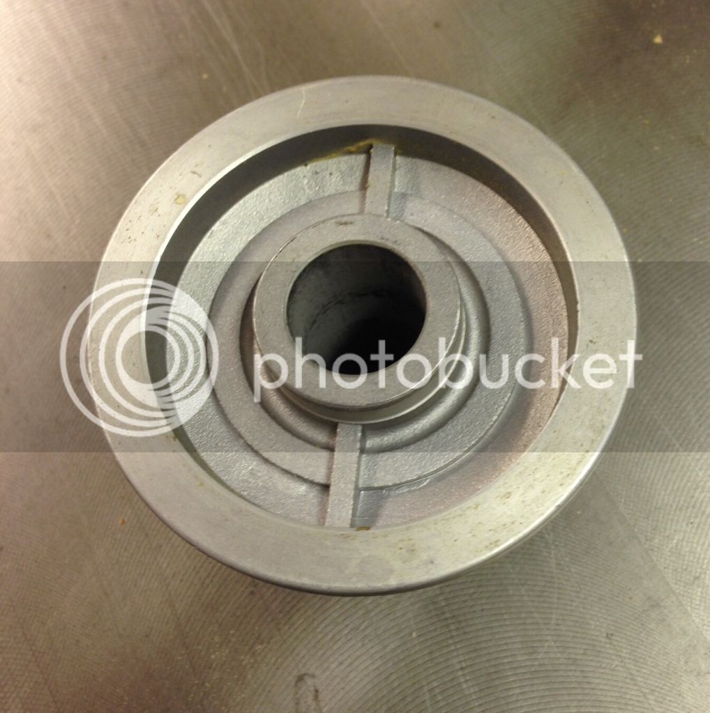
I want to modify a (spare) flange for the spindle on my table saw. A couple of pictures are shown below. I want to trim off approx 6mm from the face of the outer ring to accommodate a small adjustable groover set that will fit on the saw except that it has a thicker central boss (I have another similar groover that has no central boss so fits fine).
The boss on the groover means that the tool is offset towards the end of the spindle, thereby not lining up with the table saw slot and reducing thread for the securing nut.
The spindle (ie the ID of the flange) is 25mm and the OD of the inner ring (ie the tool bore) is 30mm.
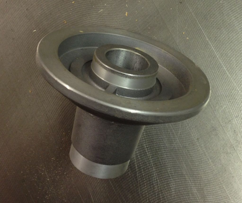
The flange is aluminium alloy of some sort I guess.
I am hoping(?) that it should be a fairly straightforward machining job to trim down the outer ring, although obviously this has to be done precisely so that I do not end up with a wobble blade!
I will check the dimensions when I get the new spare flange, but the existing one has just over 5mm before it gets to the two lateral bars, so 6mm would skim off almost 1mm of those.
I am not really seeking advice on whether to do this, but rather how I could get it done. I do not have a metalworking lathe - Is there a member who could/would do it or does anyone have any suggestions on how I would find a machining shop to do this. In terms of location, I am near Stratford-upon-Avon and travel regularly to Cornwall, so any ports in between!
Any help would be much appreciated.
Cheers
I am hoping someone may be able to help or advise.
I want to modify a (spare) flange for the spindle on my table saw. A couple of pictures are shown below. I want to trim off approx 6mm from the face of the outer ring to accommodate a small adjustable groover set that will fit on the saw except that it has a thicker central boss (I have another similar groover that has no central boss so fits fine).
The boss on the groover means that the tool is offset towards the end of the spindle, thereby not lining up with the table saw slot and reducing thread for the securing nut.
The spindle (ie the ID of the flange) is 25mm and the OD of the inner ring (ie the tool bore) is 30mm.


The flange is aluminium alloy of some sort I guess.
I am hoping(?) that it should be a fairly straightforward machining job to trim down the outer ring, although obviously this has to be done precisely so that I do not end up with a wobble blade!
I will check the dimensions when I get the new spare flange, but the existing one has just over 5mm before it gets to the two lateral bars, so 6mm would skim off almost 1mm of those.
I am not really seeking advice on whether to do this, but rather how I could get it done. I do not have a metalworking lathe - Is there a member who could/would do it or does anyone have any suggestions on how I would find a machining shop to do this. In terms of location, I am near Stratford-upon-Avon and travel regularly to Cornwall, so any ports in between!
Any help would be much appreciated.
Cheers