bandsaw motor help

UKworkshop.co.uk

Help Support UKworkshop.co.uk:

This site may earn a commission from merchant affiliate links, including eBay, Amazon, and others.

bob_c

Established Member
Joined
8 Jan 2008
Messages
246
Reaction score
0
Location
Cumbria
I ,ve been running a 3 phase Jet JWBS-18 bandsaw off an inverter that has 1ph 240v input and 3ph 400v output, the inverter has suddenly gone dead and ive decided id rather fit a replacement single phase motor instead of going the invertor route again or trying to get it fixed.
I need help in the type of motor i need .Id rather find a cheaper motor than the direct Jet 1ph replacement which is around £200.Also the 1ph Jet motor is only 2hp as oppsed to 3hp 3ph.Do i have to fit a 1.5kw motor or can i fit a 2.2kw 1ph.Machine mart and other places sell motors around £100 which is half the price of what id been quoted.
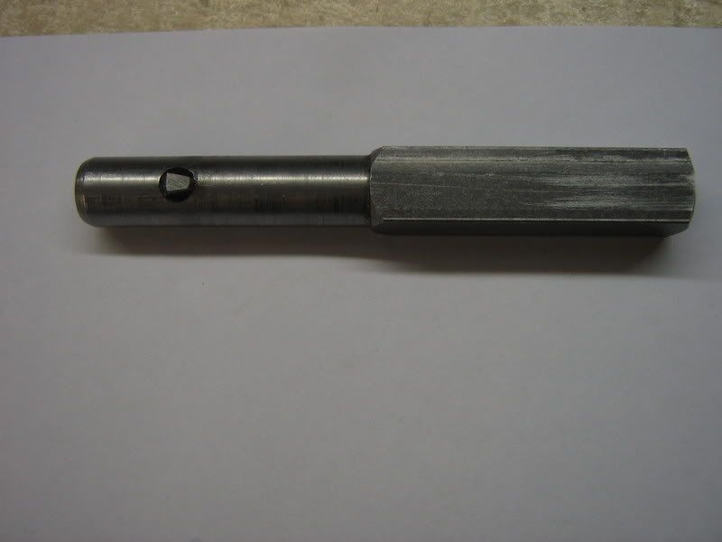
Ive taken a pic of the 3 ph motor removed and the mounting plate.
The shaft is 65mm in length from the motor ,or 61mm with the mounting plate in place.The shaft is 19.00mm (having been reduced from around 20.00mm) .The keyway goes almost the full length of the shaft and is 6mm x 3mm(to fit a 6mmx 6mm key).The motor is secured to the bandsaw side by two bolts one at either end of the mounting plate(see pic).The motor fixes to the mounting plate by the four bolts which arent on a circumference of a circle,being approx.100mm and 80mm apart.
Any suggestions appreciated .Also im a bit confused by the motor terminology. 2pole/4pole etc? Capacitor start/capacitor run???The original motor has a speed of 1400.
399628109-002.JPG

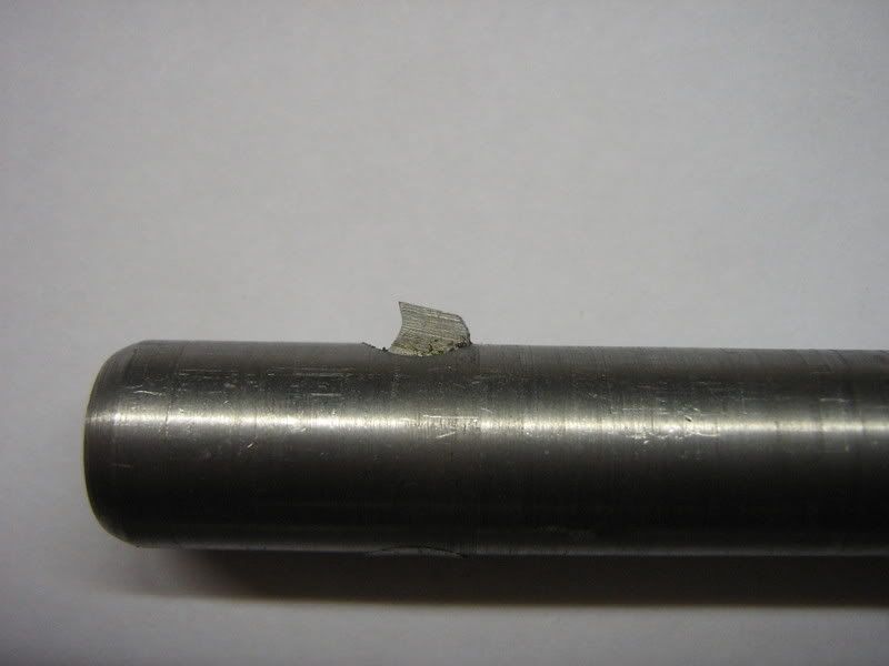
Heres a pic from inside the bandsaw showing the 2 mounting holes ,the large hole cut out is 120mm diameter.
980829107-002.JPG
 
First criteria is that you will need a 4 Pole induction motor, to get the equivalent 1450 rpm @ 50 HZ.

If you go for anything above 2HP (1.5KW) you may need to improve your supply source to accommodate the start surge demanded by the single phase motor.
 
Thanks for the reply so 4 pole,why??Im thick concerning motors.The supply at the moment if through armoured cable from a dedicated 20amp type B mcb.(i was told that these are better as they dont trip with a startup surge)
 
bob_c":p37c3432 said:
Thanks for the reply so 4 pole,why??Im thick concerning motors.The supply at the moment if through armoured cable from a dedicated 20amp type B mcb.(i was told that these are better as they dont trip with a startup surge)

Your supply should be adequate, for either motor choice,

Poles: A 2 pole motor (the more common) runs at a nominal 2800 rpm a 4 pole motor at 1450 rpm, this is inherent in the design & governed by the supply frequency.
 
Secondly, the existing motor might not use a standard mounting arrangement. It does not look standard flange but I could be wrong.

19mm shaft is on the small side for 2 HP motors, 24 being more common.

When you go to buy the replacement take the plate with you. You might have to drill new holes in the plate to mount the motor if there is enough metal

Alternatively you might need to make a new plate which should be easy enough if you have metal working kit. Similarly the shaft diameter can be reduced and a new keyway cut.
If you have to pay a local engineering shop to do these jobs then you are possibly better off buy the correct motor from Jet to be honest.

I have a feeling that there is a JET representative who lurks on this forum.
It maybe that he could offer a more economic solution??

Bob
 
thanks for the explanation of 2 pole /4 pole.
Bob, i can see what you mean,the motor doesnt appear to have what id call a flange,more just like 4 threaded holes in the end of the motor housing. I have a small milling machine and equally small lathe. I dont think making a mounting plate is a problem.But problems seem to be the shaft diameter and keyway.Also mounting the plate to the motor.The existing plate isnt that robust ,and i assume a 3hp motor as opposed to the Jet 1ph replacement at 2 HP will be heavier.Or will a 3 hp 3ph motor weigh the same as a 1ph 3hp motor??Also i assume i,ll lose alot of power putting the JET 2hp motor on?
Also will a dual voltage motor be alright for single phase,or are they meant for inverter use?
 
Another thought,wouldnt it be easier just getting a new pully to fit the shaft,rather than mess with the motor??
 
Bob,
Dual voltage is something normally associated with 3 phase motors. I've not seen dual voltage single phase apart from very small/low power motors.
Can you cite an example of dual voltage in this power range?

The greatest impact on motor weight is cast iron or aluminium casings. Cheaper motors tend to be CI ( a complete contrast to the tables on ww machines!) and weigh a lot more. I guess the current Jet one is CI?
Like for like a 3phase motor will be a little lighter than the equivalent single phase version.

Yes the mounting plate does not look very substantial but no point in beefing that up if the body it bolts to is only sheet metal.
2 bolt fixing is poor practise anyway as it defines a single axis for flexure. ideally the two bolt holes would be in line with the tension in the belt but that does not give much adjustment for belt tension.

Getting a pulley of correct diameter, correct V section (or is it poly v or toothed?) and the correct bore might not be easy. There might not be enough meat on the old one to bore out to 24 and a larger key way.

If you have a lathe then shaft reduction is simple if you can get the rotor between centres. Cutting a keyway in a shaft is a trivial milling job (unlike cutting one in a pulley)

hth
Bob
 
Doesnt matter about the dualvoltage, thats just me talking rubbish,i said i`m thick where motors are concerned. Heres a pic of the pulley,not sure what sort of belt it is.Poly?? It seems to be cast iron or steel.Has a key way and four grub screws. the thick bit is 40mm diameter.So not sure if there would be enough room for a 24mm shaft.
41971441-001.JPG

59459987-003.JPG
 
Hi Bob,

That is a single vee pulley (poly V have a number of small vee grooves and a special belt to match - often found in washing machines).

24 mm bore in a 40mm boss is a bit marginal to allow room for the keyway and a grub screw on top but in this case, the saving grace are the two grub screws in the bottom of the vee groove. They will take most of the load and keep the key locked in place.
All you will have to do is to set the pulley in the 4 jaw chuck and get it perfectly centred on the existing bore and then open out to 24mm then cut the new keyway in the same position as the old one.

hth

Bob
 
Thanks Bob, i know what you mean by poly vee belt now. Any tips on cutting the keyway,would an hacksaw and a square file work with alot of effort.Im guessing a 24mm shaft will have a 8mm keyway?So that would only be around 4 mm deep across 40mm in length.SHouldnt be that hard?

Just noticed now that all the cheaper 3hp motors are 28mm shaft size.Some 2 pole have 24mm shafts.
Is capacitor start/capacitor run 4 pole the right type to get?
 
Hi Bob,

Keyways cut the way you suggest are a bit hit and miss.

I cut them in the lathe with the mandrel locked (motor off!!) and a slotting tool set in the tool post at centre height. The carriage is racked back and forth advancing the tool about a thou at a time.
Here are pictures of a tool I made recently for a much smaller keyway
Slottingtool001.jpg


Slottingtool002.jpg


The width of the cutting tool is ground to be a thou wider than the key
with a few degrees clearance on the sides and back. The top rake is cut by touching the edge of the grinding wheel behind the cutting edge and final honing to sharpen.
The tool bit is set in the holder by a grub screw threaded in from the end of the holder.

Bob
 
bob_c":15wql7yf said:
.... Any tips on cutting the keyway,

Having opened up the bore in your lathe, with the pulley still mounted centrally in the chuck, mount a TCT tipped 3-4 mm parting tool on its side in the toolpost so that its top is facing you.

Lock the the lathe spindle, and by advancing the saddle by hand, progressively form (shape) the keyway in the side of the pulley bore.

Adjust the tool height in the post to achieve the required keyway width.

Edit: Beaten to it by Bob. with the proper tool.
 
I use the same technique. Slow, but guaranteed to get you there.

Roy.
 
Bob,

I've just been following another thread about 230-400v inverters.
TECO are one of the few of these on the market and one sure way to kill these is to have any switching between the output of the inverter and the motor. All the motor controls must be done via the inverter and power disconnection done on the input side of the converter.

I wonder if there is any connection between this failure mechanism and the way you were driving your bandsaw motor?

Just a thought?

Bob
 
IIRC, Jet cite output power, rather than input power, in their specs so the 2hp motor is likely to be around 3hp input anyway. If that makes a difference to your decision making.
 
Thanks for the suggestions for cutting keyways.
The inverter i had was connected up with nothing between the inverter and motor.I had an isolator between the mcb and the inverter.I controlled the speed,on /off etc.. with the digital panel on the invertor.I havent a clue what happened because the bandsaw wasnt even on at the time,i just heard a small bang like a fuse and it went dead.Ive looked inside and nothing looks burnt,no smell or anything.I wrote to the maufacturer who reckoned it could be one of the capacitors and if it is then its fatal.But since that ive heard that they make a bit of a mess when they blow.They look fine.I was also told they dont have a changable fuse either.Totally stumped as to what the bang was.
 
Jake":3ilup9s5 said:
IIRC, Jet cite output power, rather than input power, in their specs so the 2hp motor is likely to be around 3hp input anyway. If that makes a difference to your decision making.
Where does it say this?
In these specs it says 1400w input and 2200w for 3 ph which is what i have now.
Mine is the mk1 version.
http://www.jettools.co.uk/jwbs18mk2.html
 

Latest posts

Back
Top