Stimpi
Established Member
Under Stairs cupboards. No live animals, rules or tapes were used during the making of this post.
This is a project I have been considering for some time to which I have now made a start.
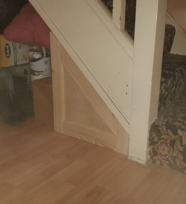
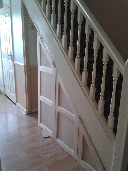
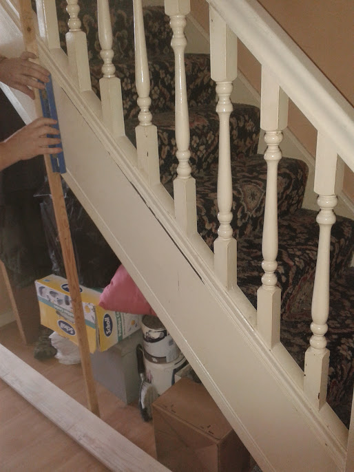
These are the stairs in question, quite normal, a straight flight with a quarter space landing top and
bottom.
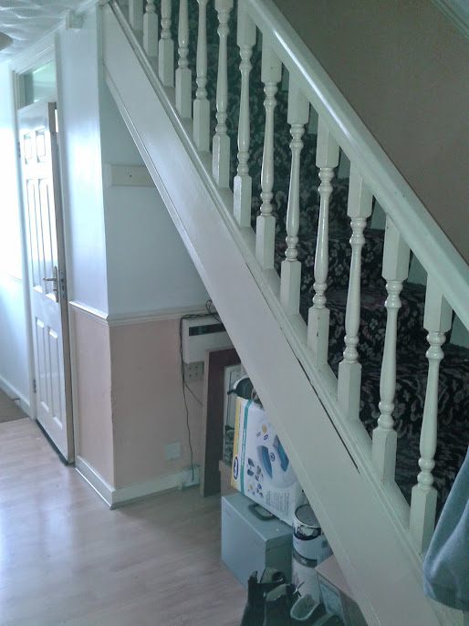
It has been a rainy day project for some time now with me toying with ideas with how the design should go. The job is now a goer and with Sharpy86 showing an interest last April I need to be prepared for questions and plenty of pictures .
One factor always constant in my mind is it is on the top floor level of a block of London flats with no lift. Everything has to be humped up a load of stairs. Another factor is I can only get up to London one day a week which will affect progress.
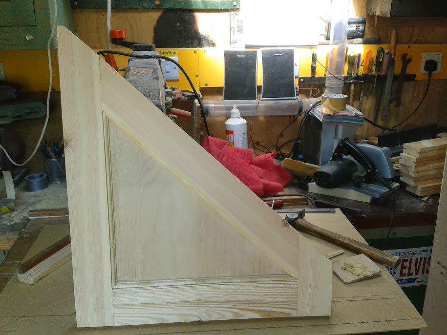
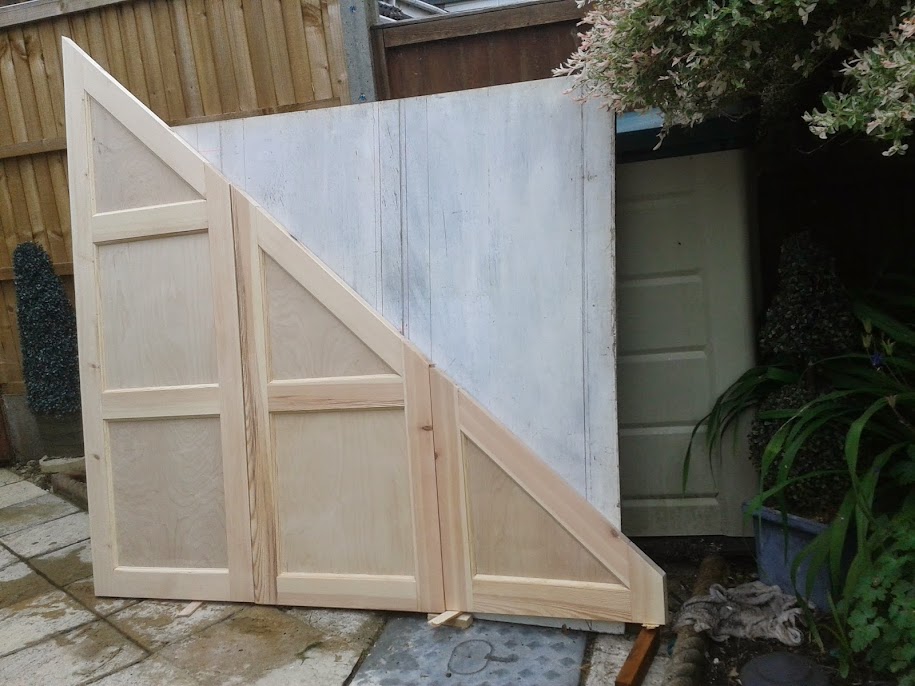
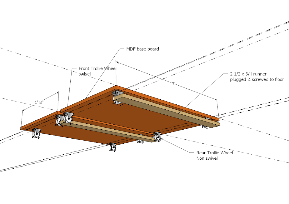
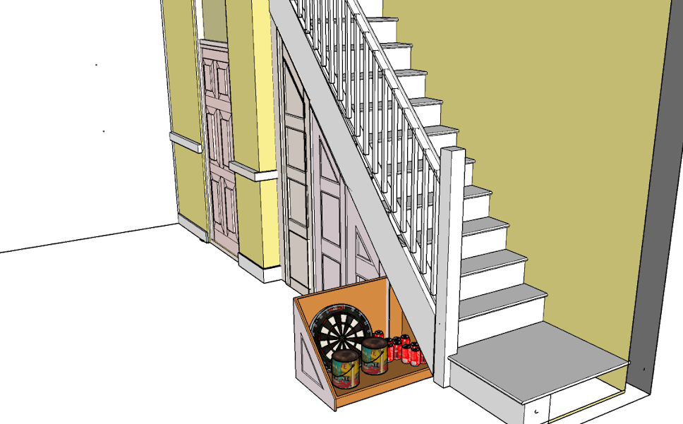
The way I wanted to go was constructing pull out cupboards on trolley wheels but the client did not want this with the and had a preference for a flush surface using MDF.
In the end it has come down to cost. Framed/paneled softwood is cheaper than MDF, easier to hump up stairs, I can transport it my self with own transport (£18.00 delivery charge on MDF), fabrication easier and I can fabricate at home in my own workshop. Still have to transport the gear to London.
So this is the plan
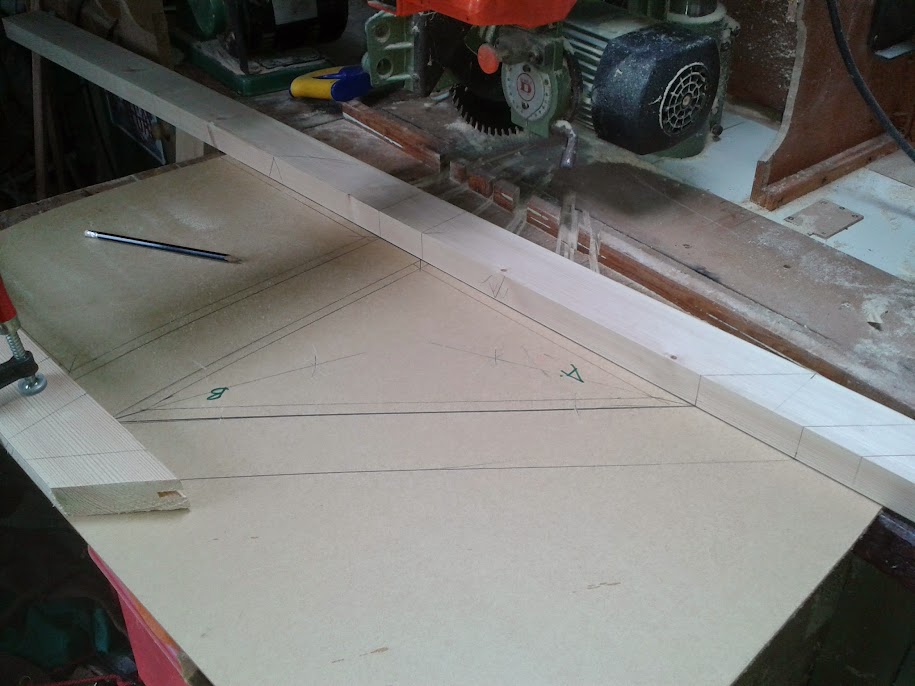
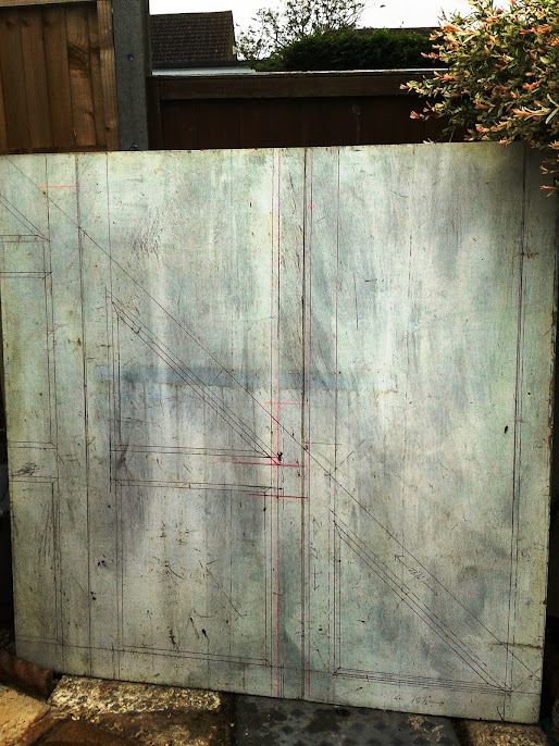
Staircase work is all about angles and work with angles is unforgiving, due to inaccuracies being exaggerated. Accuracy is the key which is why I prefer the use of Rods. Rules and tapes are left at home. Example, if I cut a joint 1/32”, out the discrepancy will grow just short of ¾ “ in a foot.
The first task was to secure a 3” x 1 ½” vertical post plumb in both directions on the face at the high point of the spandrel. This is my reference in producing a rod. I call this reference point A
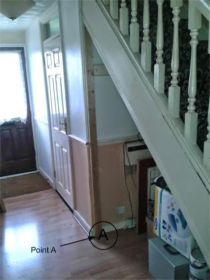
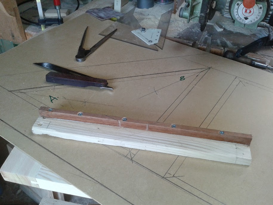
Reference Points for the rod. That is, physical marks are made between the reference point A and the newel Reference point B
This then has to be divided equally into four. I did this using geometry on a flat surface.
The flat surface I used was the client’s kitchen floor which was covered with a grey vinyl tile.
I will try and illustrate the theory with sketches rather than photo’s and then try and explain what I did and, why it was a simple process even without the use of rules or tapes.
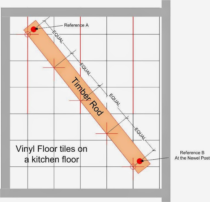
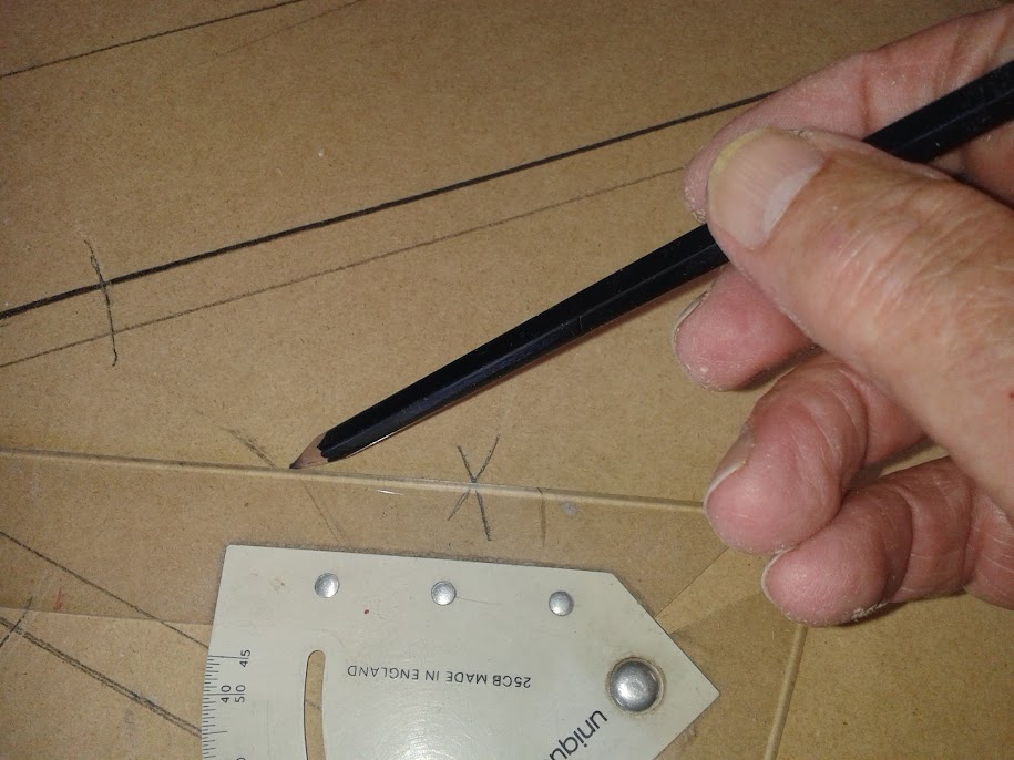
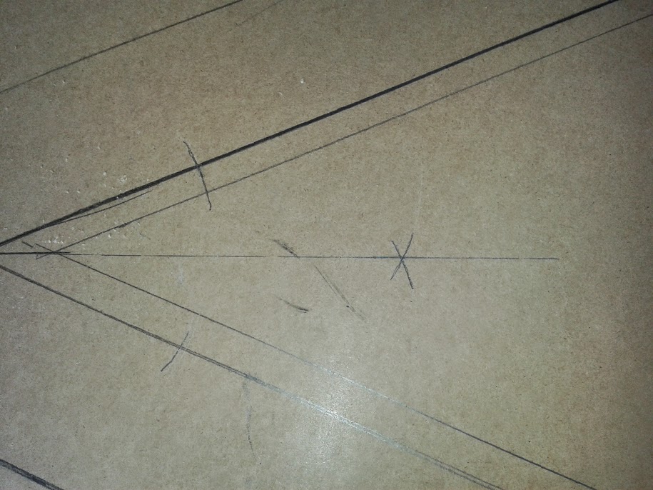
I selected eight tiles as the A – C line fist placing pencils and bits of wood as demarcation. Brought to it the Rod with its two reference points matching the A reference with the first demarcation pencil. And swinging the B reference to form the angle till it met the tile line.
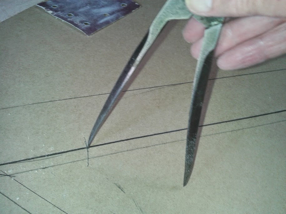
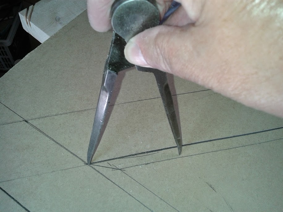
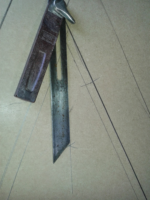
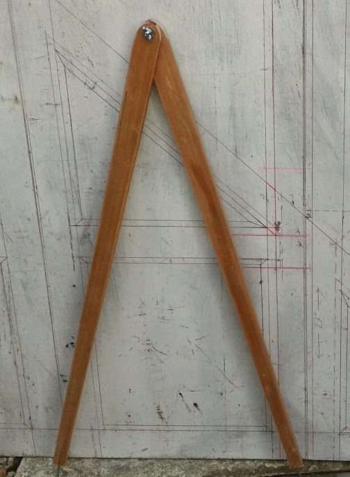
A useful piece of kit, easily made was used to check the spaces are equal which are, an overgrown pair of dividers. Useful for checking the divisions are equal.
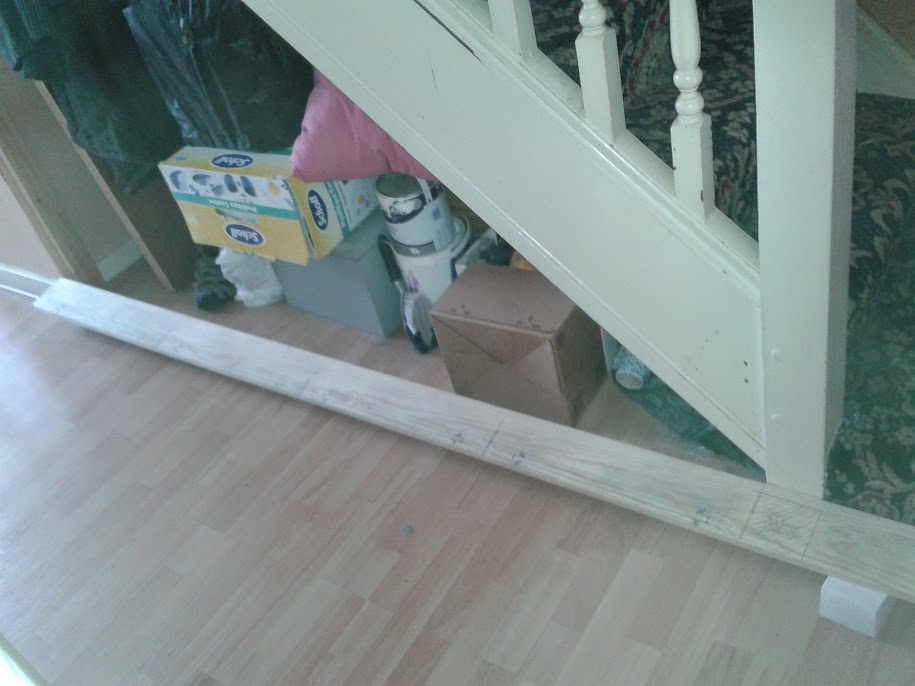
I then took this Rod to the stairs, lined up the reference points and transferred the divisions on to the floor.
These marks were plumbed up and marked on the stair string plus marking the heights on a story Rod
With this information I drew more detail into the Rod using short ends of material positioned either sides of the marks.
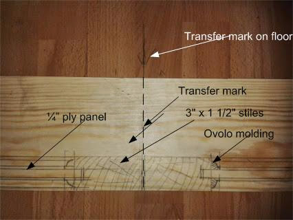
With this information I drew more detail into the Rod using short ends of material positioned either sides of the marks.
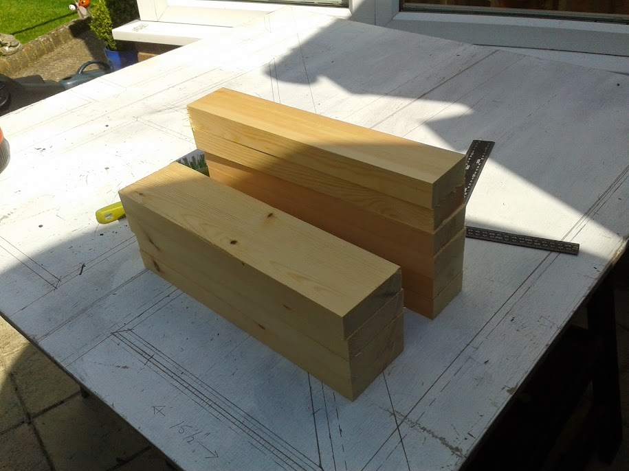
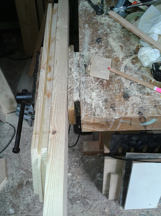
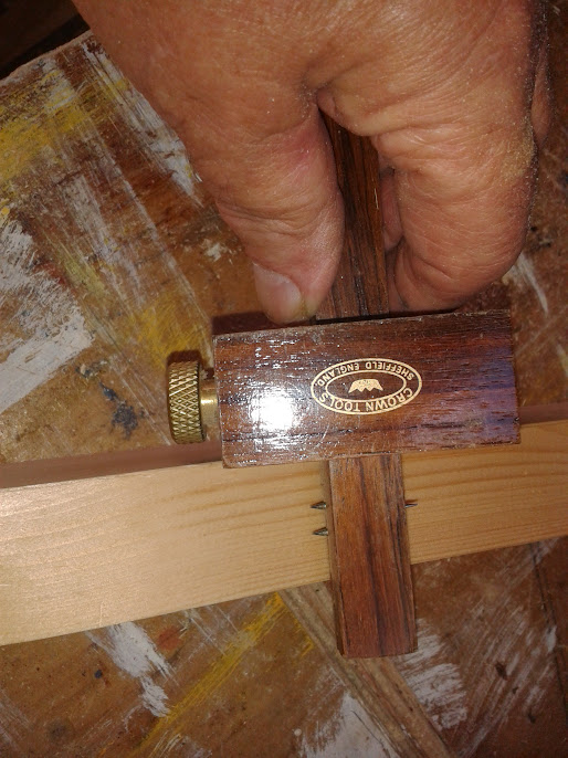
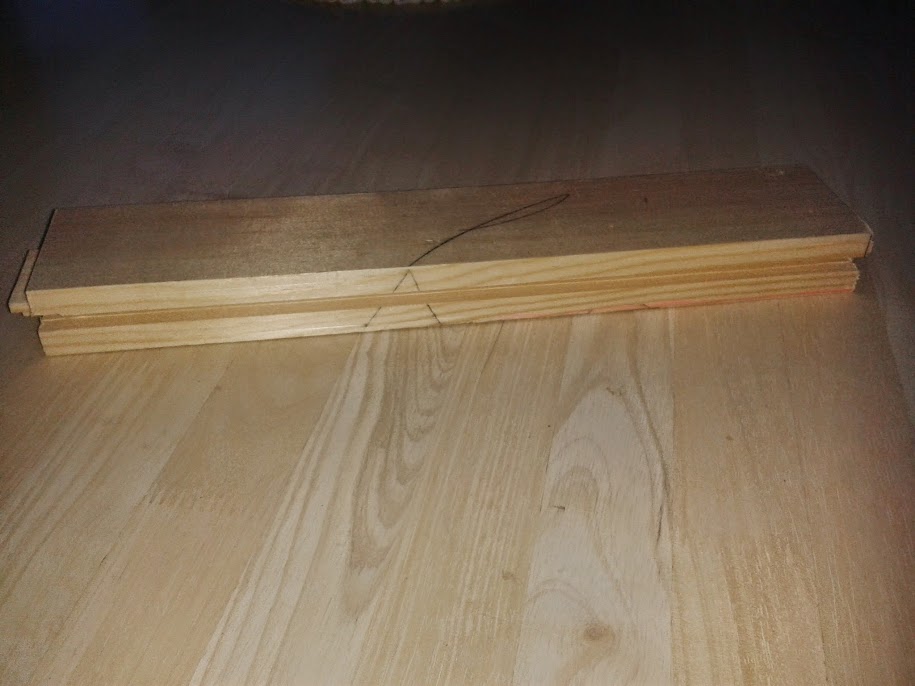
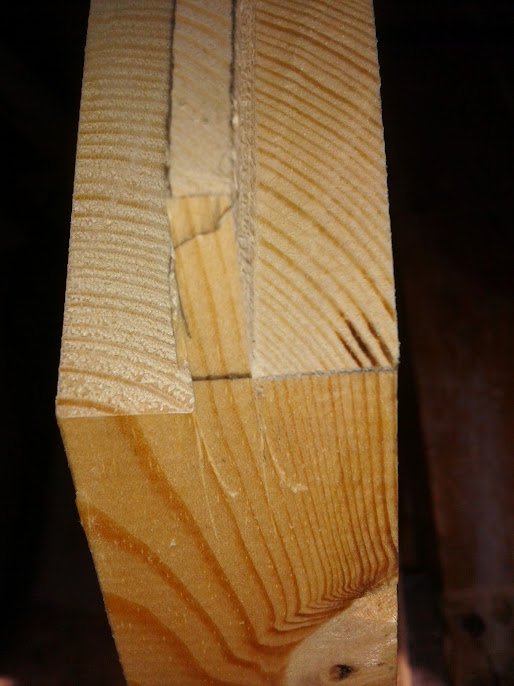
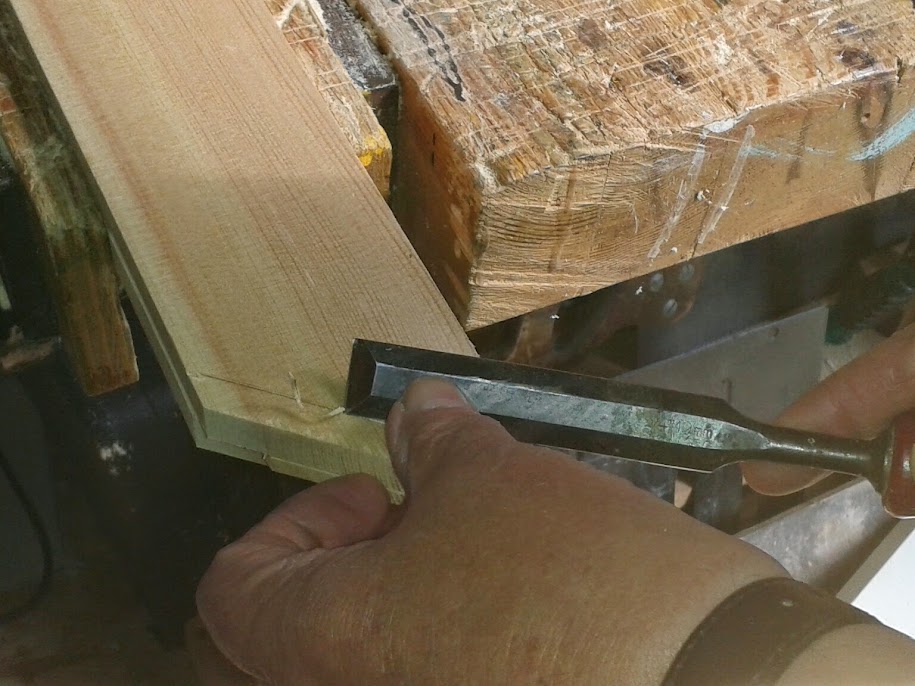
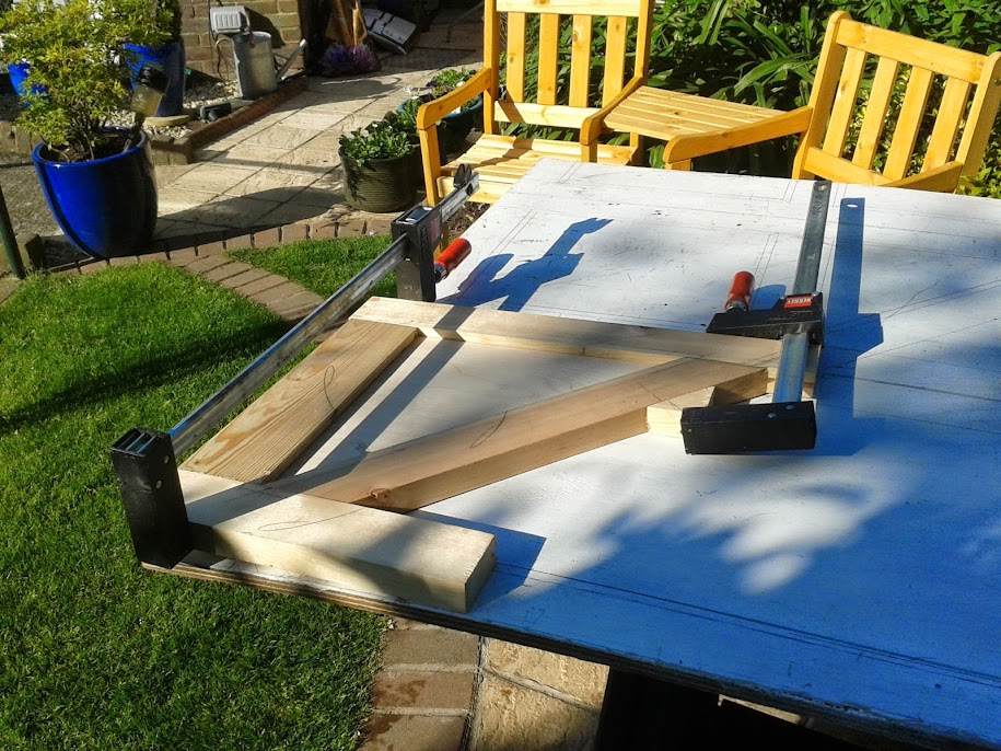
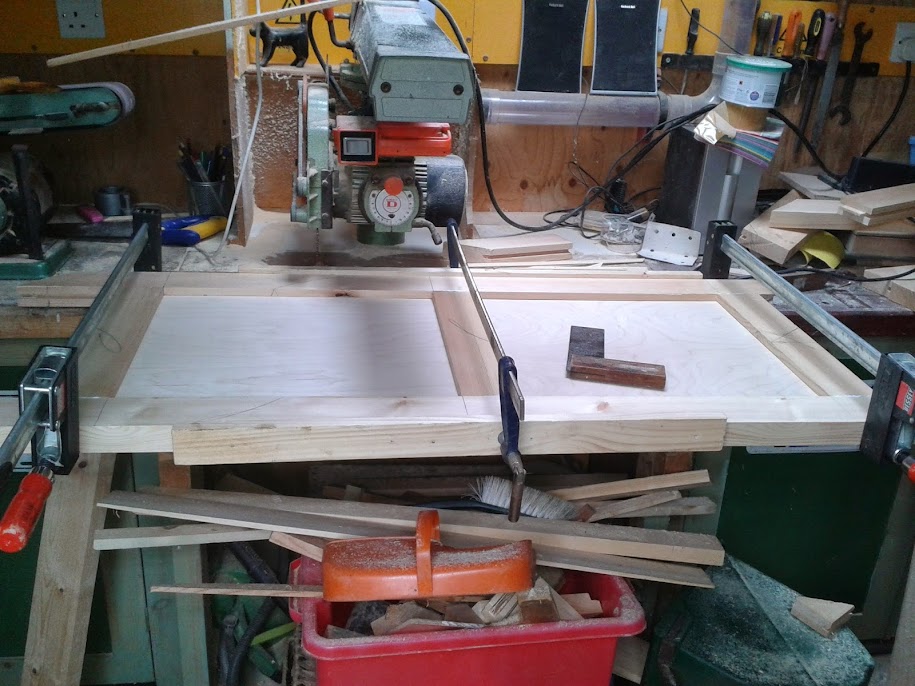
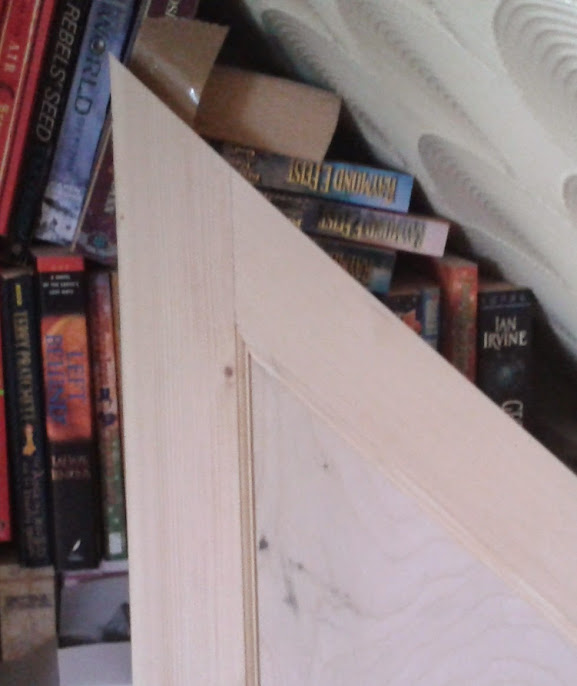
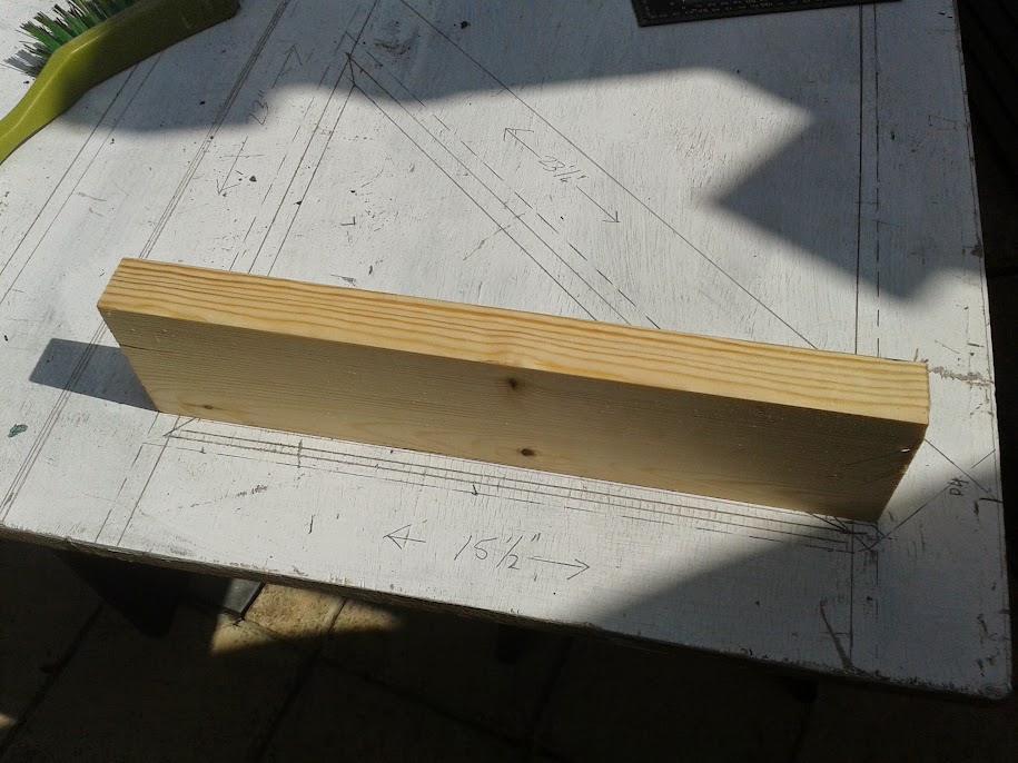
This was the setting out complete and cutting the stock to size began, gauging all like members to these Rods.
This is a project I have been considering for some time to which I have now made a start.
These are the stairs in question, quite normal, a straight flight with a quarter space landing top and
bottom.
It has been a rainy day project for some time now with me toying with ideas with how the design should go. The job is now a goer and with Sharpy86 showing an interest last April I need to be prepared for questions and plenty of pictures .
One factor always constant in my mind is it is on the top floor level of a block of London flats with no lift. Everything has to be humped up a load of stairs. Another factor is I can only get up to London one day a week which will affect progress.
The way I wanted to go was constructing pull out cupboards on trolley wheels but the client did not want this with the and had a preference for a flush surface using MDF.
In the end it has come down to cost. Framed/paneled softwood is cheaper than MDF, easier to hump up stairs, I can transport it my self with own transport (£18.00 delivery charge on MDF), fabrication easier and I can fabricate at home in my own workshop. Still have to transport the gear to London.
So this is the plan
Staircase work is all about angles and work with angles is unforgiving, due to inaccuracies being exaggerated. Accuracy is the key which is why I prefer the use of Rods. Rules and tapes are left at home. Example, if I cut a joint 1/32”, out the discrepancy will grow just short of ¾ “ in a foot.
The first task was to secure a 3” x 1 ½” vertical post plumb in both directions on the face at the high point of the spandrel. This is my reference in producing a rod. I call this reference point A
Reference Points for the rod. That is, physical marks are made between the reference point A and the newel Reference point B
This then has to be divided equally into four. I did this using geometry on a flat surface.
The flat surface I used was the client’s kitchen floor which was covered with a grey vinyl tile.
I will try and illustrate the theory with sketches rather than photo’s and then try and explain what I did and, why it was a simple process even without the use of rules or tapes.
I selected eight tiles as the A – C line fist placing pencils and bits of wood as demarcation. Brought to it the Rod with its two reference points matching the A reference with the first demarcation pencil. And swinging the B reference to form the angle till it met the tile line.
A useful piece of kit, easily made was used to check the spaces are equal which are, an overgrown pair of dividers. Useful for checking the divisions are equal.
I then took this Rod to the stairs, lined up the reference points and transferred the divisions on to the floor.
These marks were plumbed up and marked on the stair string plus marking the heights on a story Rod
With this information I drew more detail into the Rod using short ends of material positioned either sides of the marks.
With this information I drew more detail into the Rod using short ends of material positioned either sides of the marks.
This was the setting out complete and cutting the stock to size began, gauging all like members to these Rods.