Here is the info I've got so far.
Parts 148 and 150. I have measured these in place on my machine. Your diagram shows 150 as two components (probably pivoting using a rivet) - the bar that the riving knife holder slides along and part of the parallelogram assembly; part 148 is the horizontal part of the parallelogram. On my machine the two parts of the parallelogram are held together and pivot on what looks like a rivet and the riving knife support bar is separate.
The horizontal bar of part 150 is 8.1mm x 40mm x 150 mm. The holes for the mounting bolts are centred 6mm from the end of the bar and 24mm between the centres of the two holes.
The two parts of the parallelogram assembly are 5mm x 25mm x 110mm and 6mm x 20mm x 175mm;the holes on the longer horizontal bar are 10mm on centre from the ends of the bar.
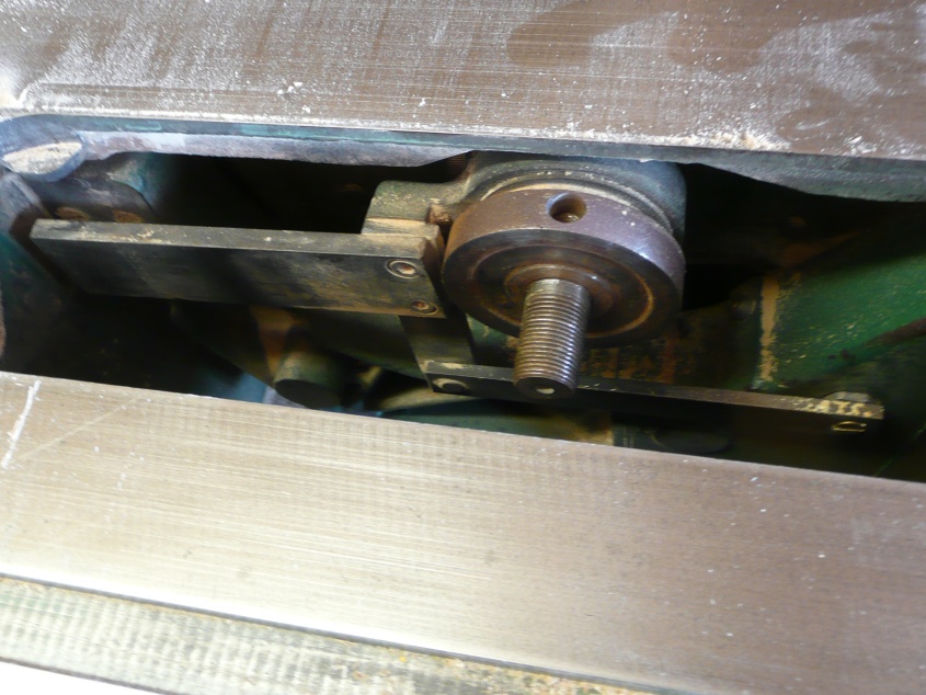
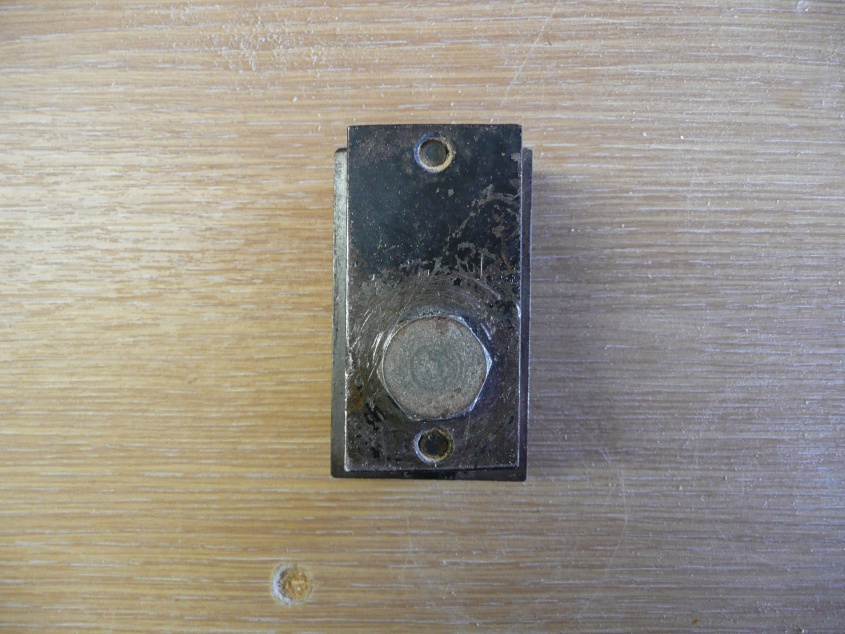
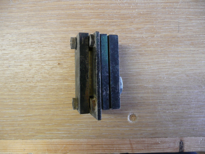
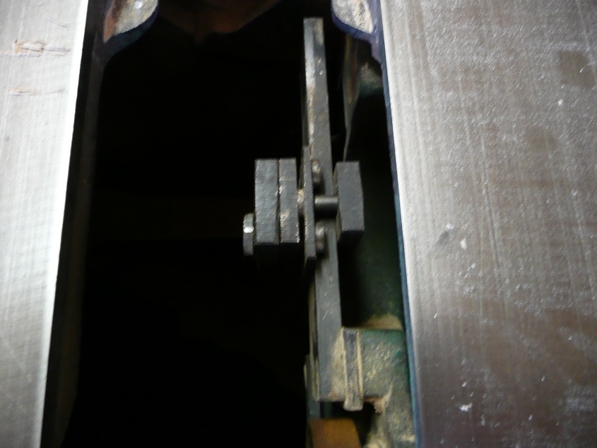
Now for the parts to hold the riving knife/guard - parts 151-156 shown in place in the saw and removed as an assembly
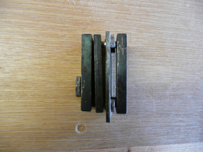
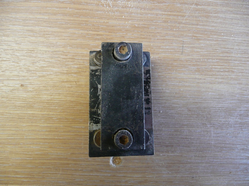
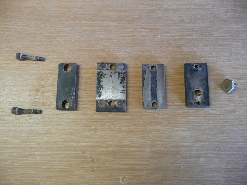
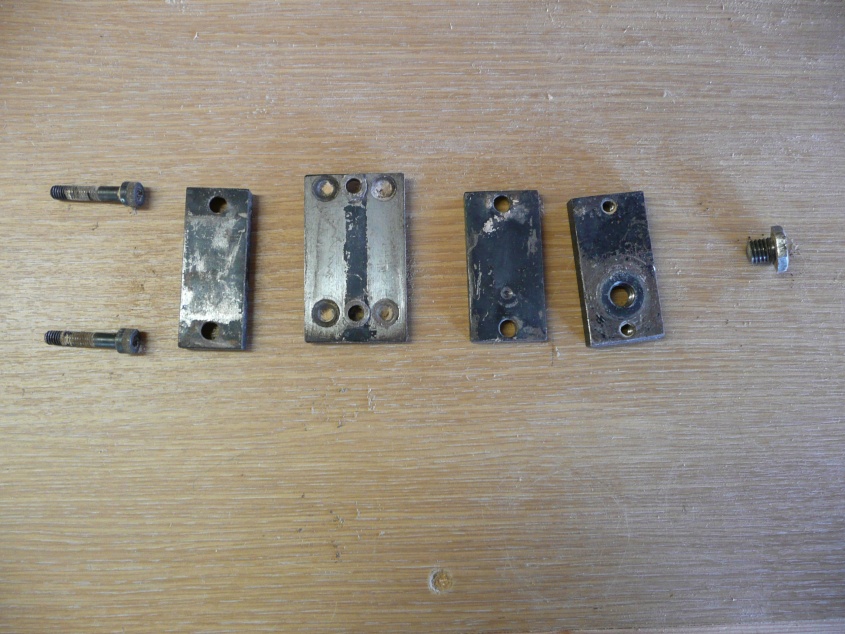
Now showing the separate parts
156 - 10mm bolt 14mm long with a thinnish (4mm)head
155 - 60mm x 30mm x 8mm with three threaded holes for the bolts 151 and 156. The 6mm holes are 50mm on centre apartand the 10mm bolt hole centre about 13.5mm from the 6mm bolt hole centre.
154 - 60mm x 30mm x 6mm with the holes 7mm to allow the 151 bolts to pass through
153 - 60mm x 40mm x 3mm. One side had 4 studs 3mm high and 10mm diameter - these allow the assembly to slide along the main support bar. On the other side there are 2 mm collars around the 7mm holes over which the riving knife slots and allows the height of the riving knife to be set. You can see the details in the pictures above.
152 - 60mm x 25mm x 8mm. These have the two 7mm holes but they are countersunk by 6mm for the 151 bolts
151 - 6mm bolts
I shall have to look at part 144 to see if I can ascertain any detail. It has to rotate around the arbor assembly but a quick look hasn't helped me understand how it does so and how it is held in place.
Hope this is of some help. If you need any more info on these parts please ask.
Misterfish