Restoration and upgrade of an old Mini Mill

UKworkshop.co.uk

Help Support UKworkshop.co.uk:

This site may earn a commission from merchant affiliate links, including eBay, Amazon, and others.

sploo

Somewhat extinguished member
Joined
8 Nov 2014
Messages
4,009
Reaction score
1,338
Location
West Yorkshire
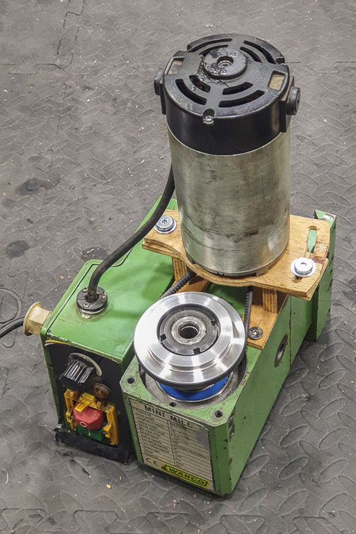
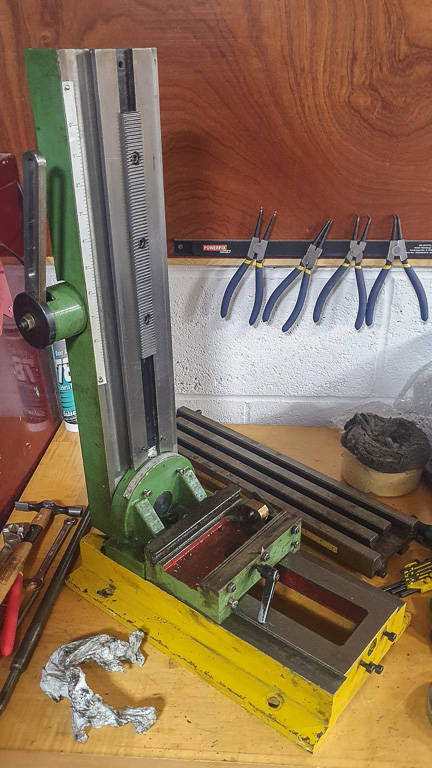
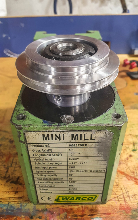
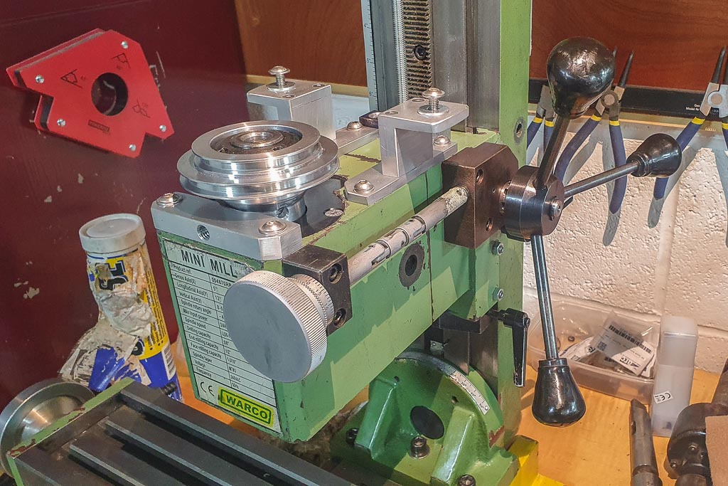
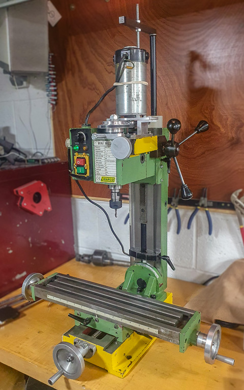
A few months ago I got a decent deal on an old Warco Mini Mill (one of the many SIEG SX2 clones). I say it was a decent deal... but on firing it up, the motor emitted plumes of smoke, and the machine itself made some fairly horrific noises. I'd planned to strip it down anyway, so...

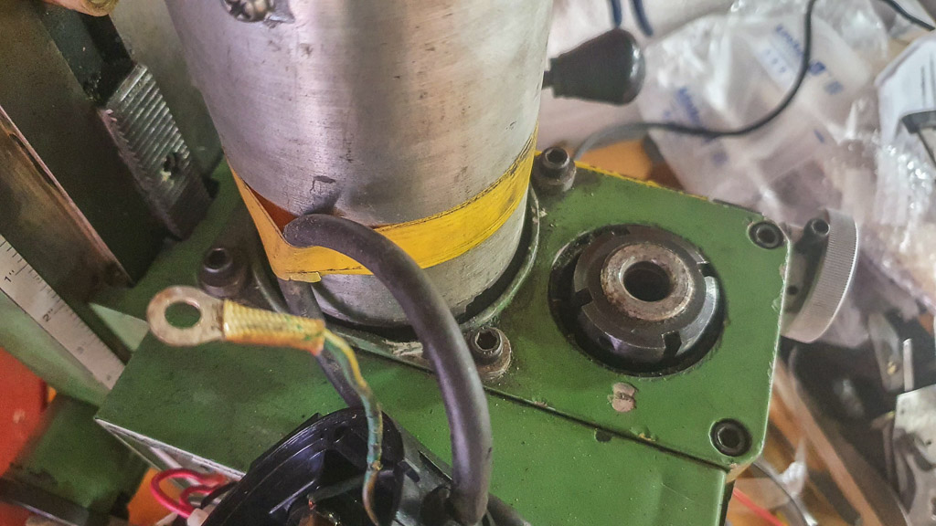
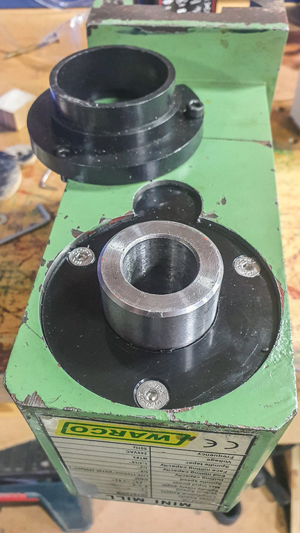
First the motor was removed, and the head taken off the vertical column:

01.jpg


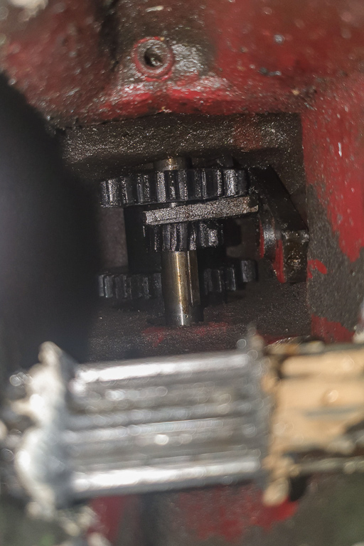
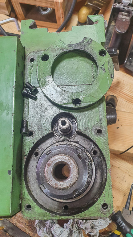
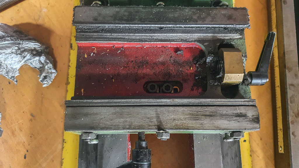
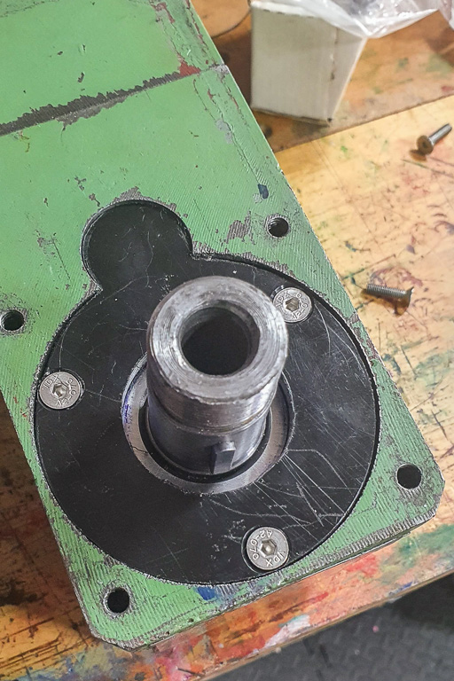
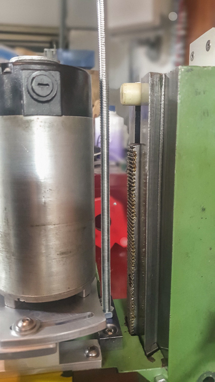
Looking inside the head it was clear the internal gearing was basically trash (apparently a common problem with this design):

02.jpg


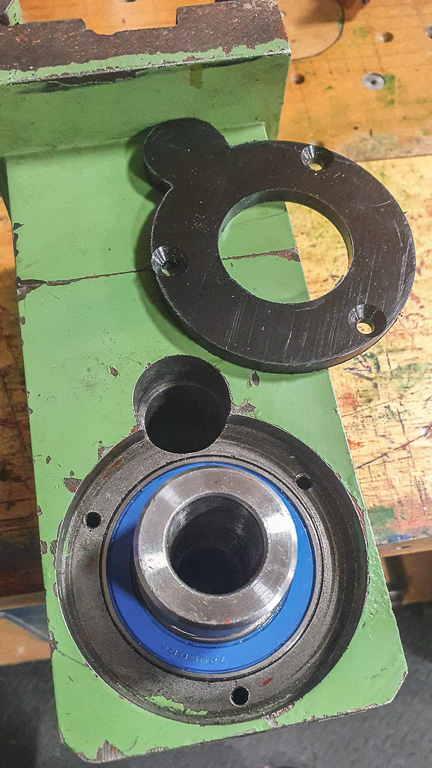
I stripped more of the head:

03.jpg


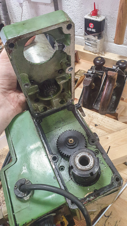
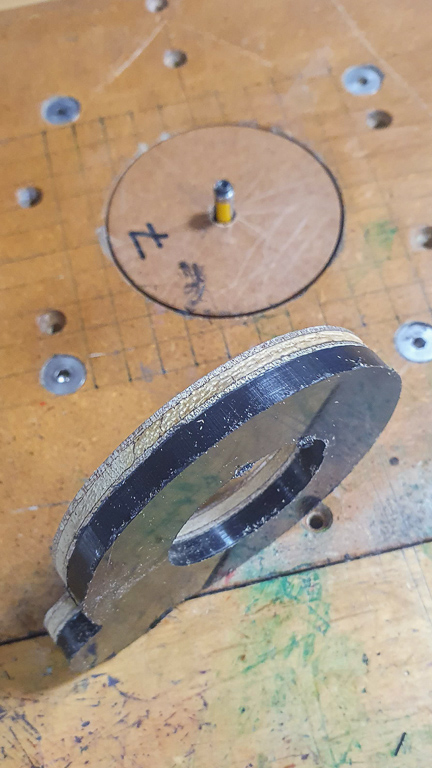
And the gears at the top looked ok:

04.jpg


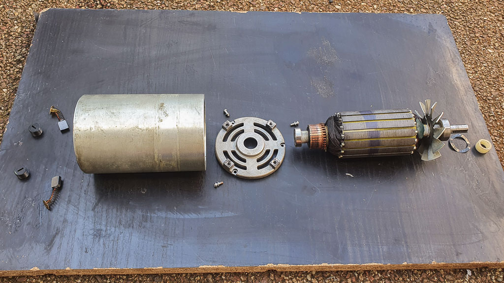
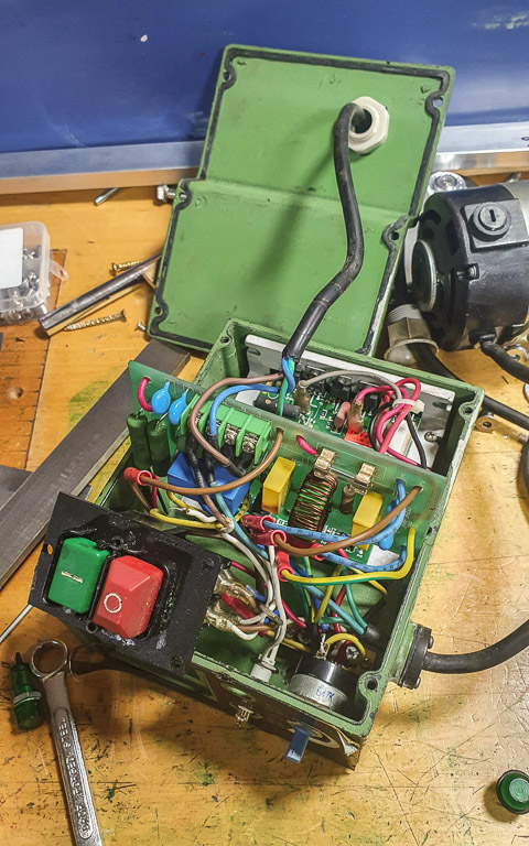
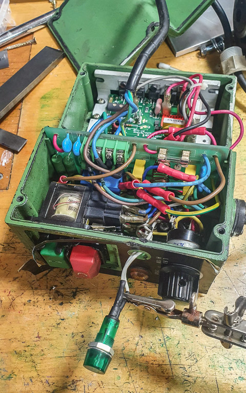
The motor was dismantled, and it turns out that a problem with the brush holders meant they'd damaged the commutator (smearing the metal and creating shorts). Fortunately I was able to clean it up:

05.jpg


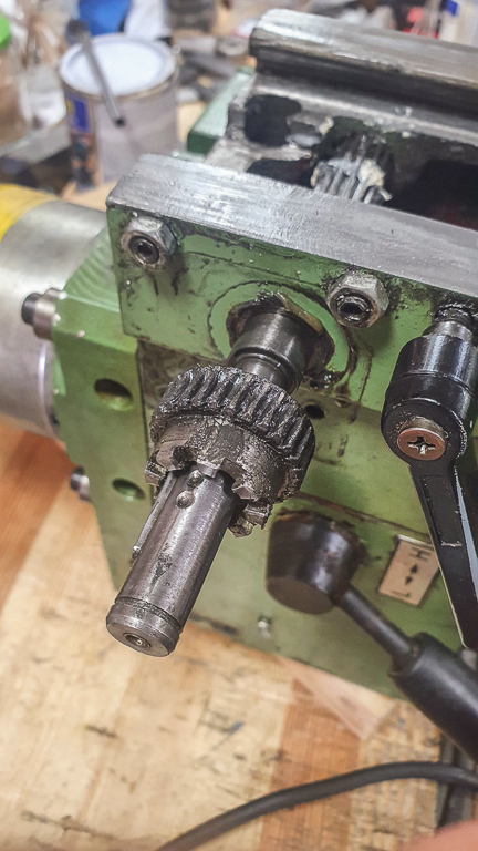
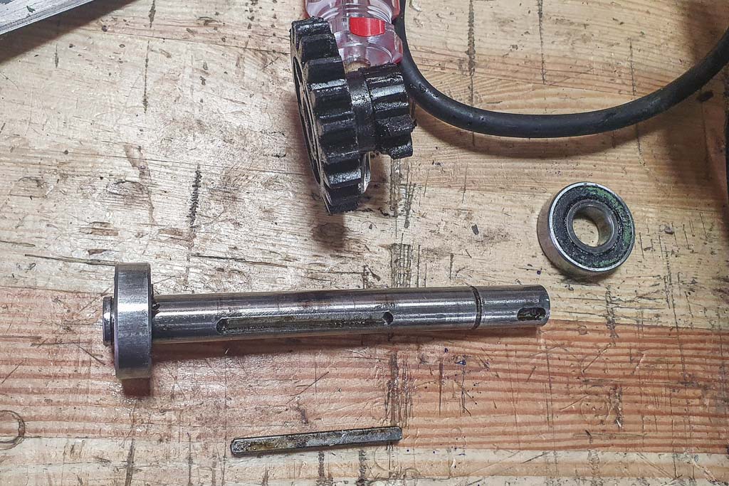
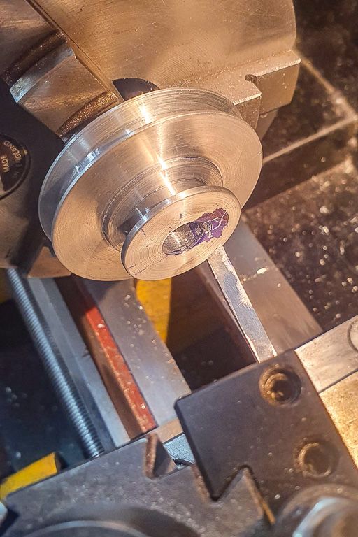
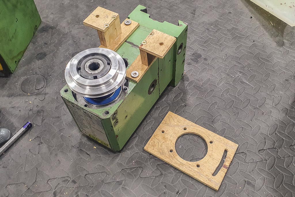
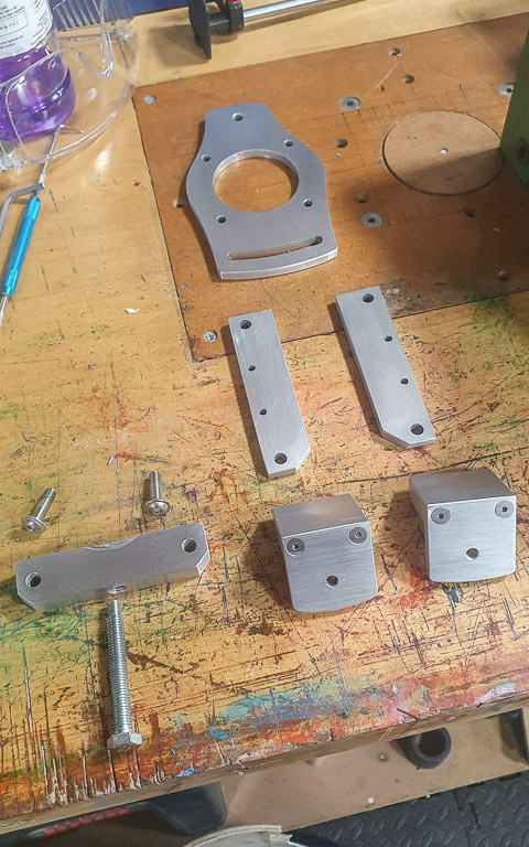
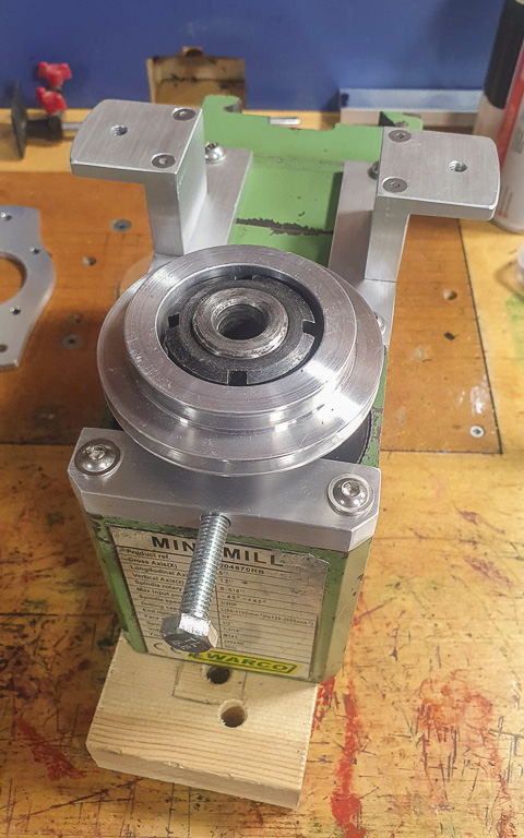
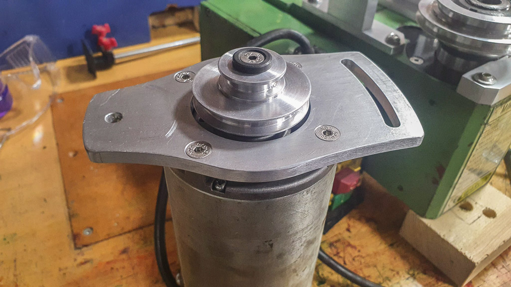
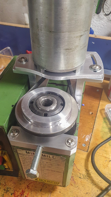
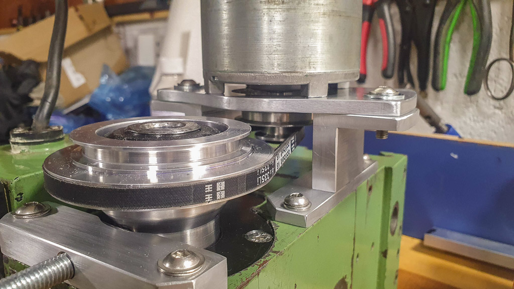
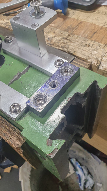
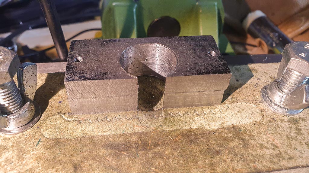
Having looked into replacement gears I decided it would be better to attempt a belt drive conversion, so the shaft carrying the change gear had to be removed:

06.jpg


07.jpg


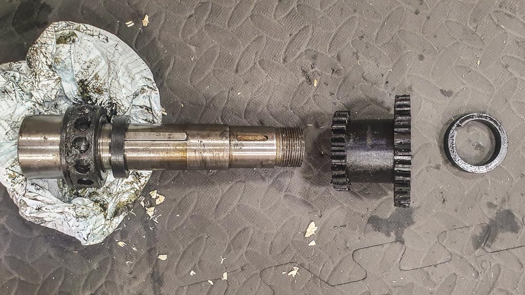
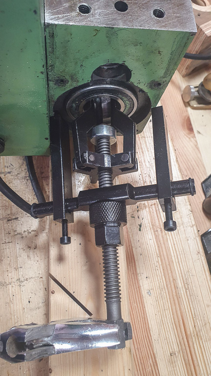
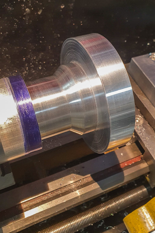
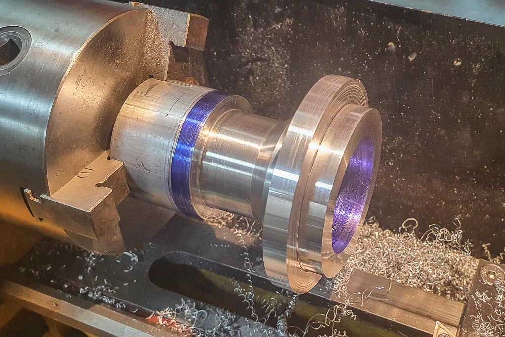
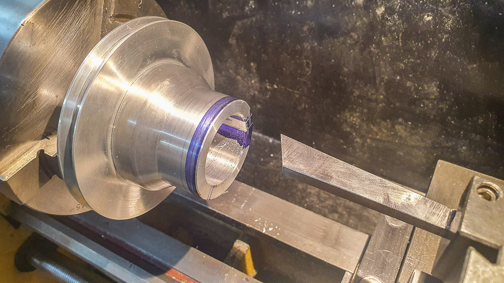
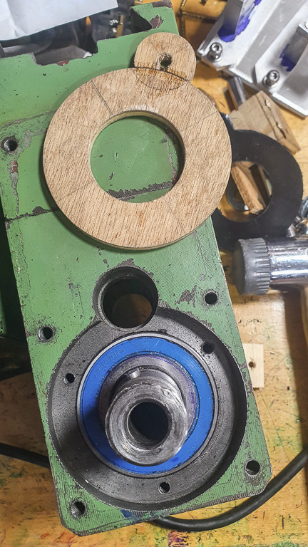
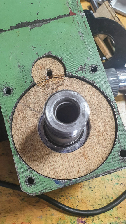
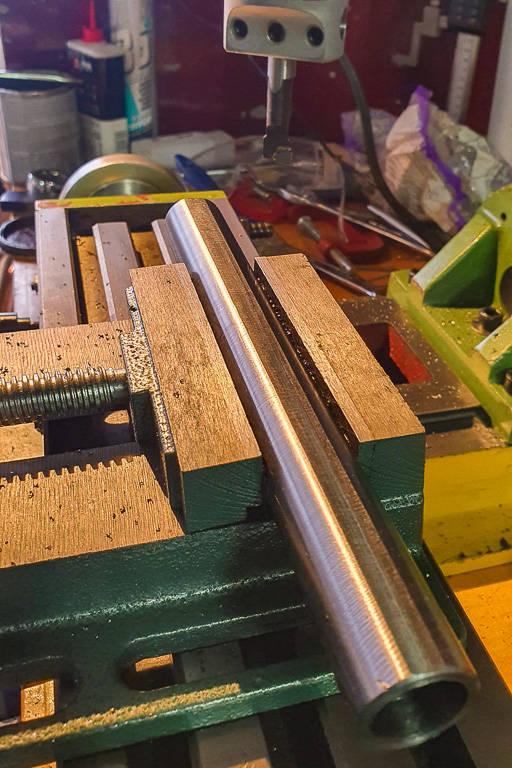
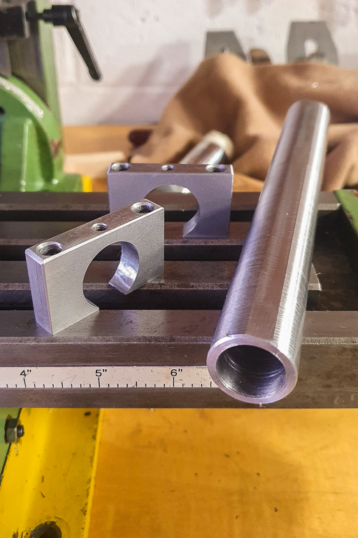
Finally, the spindle itself was pressed out:

08.jpg


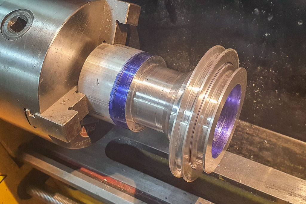
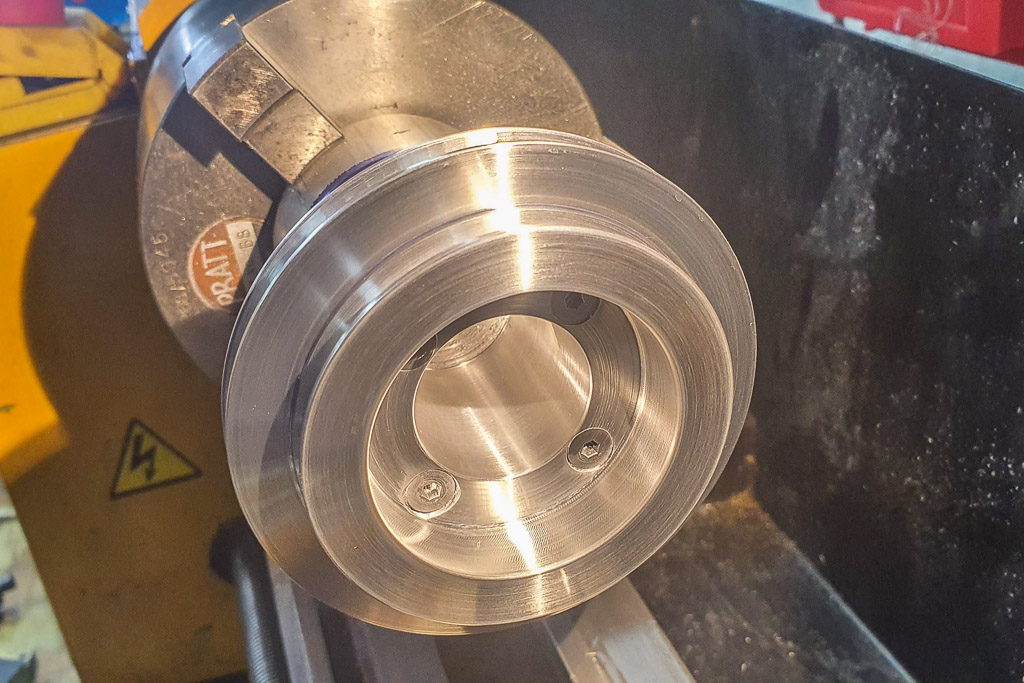
And the last of the bearings removed:

09.jpg


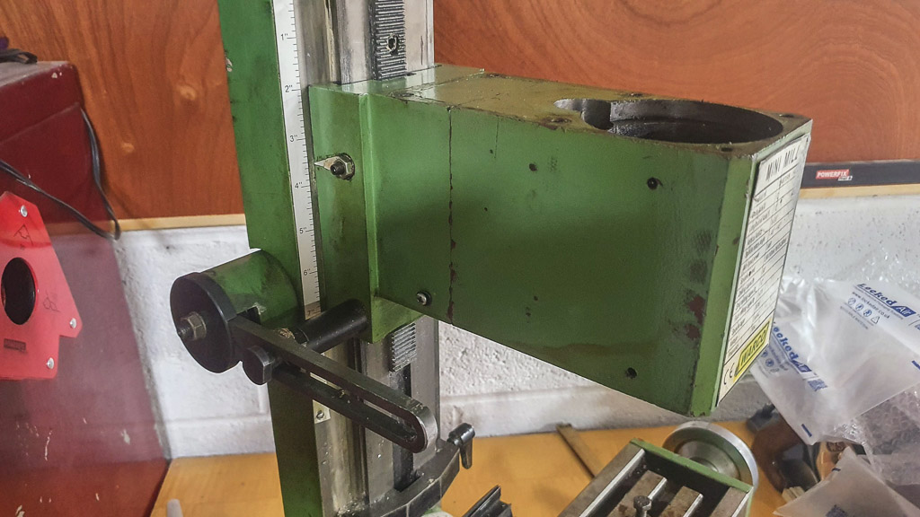
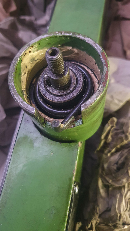
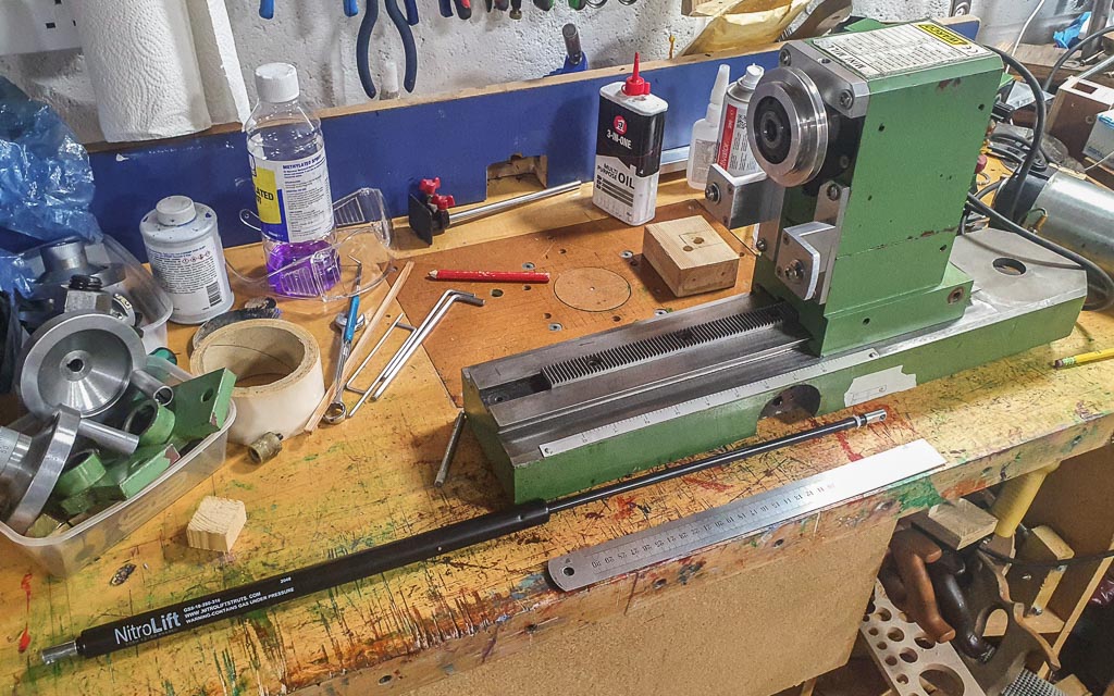
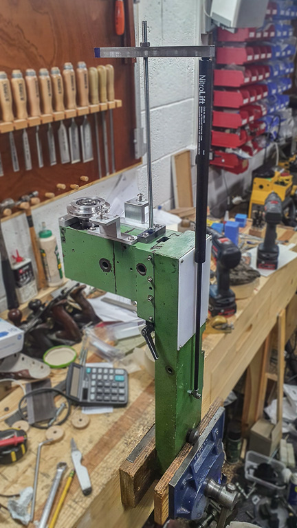
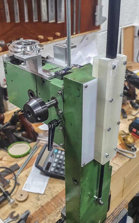
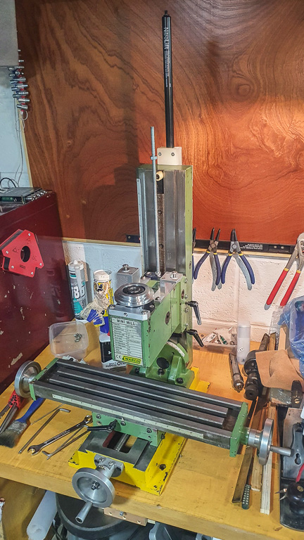
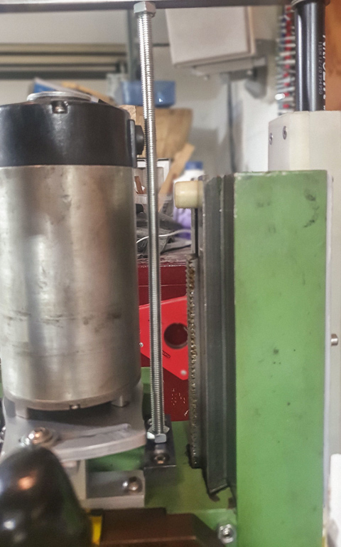
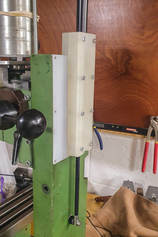
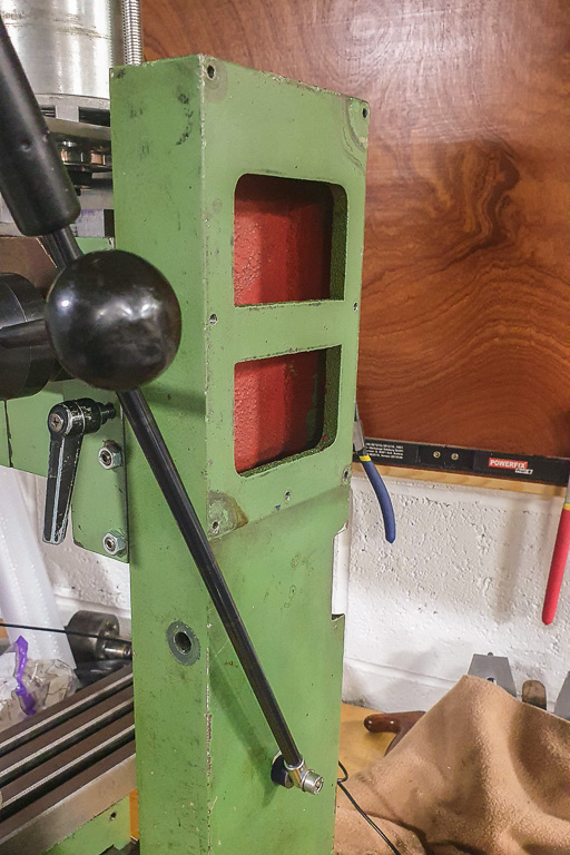
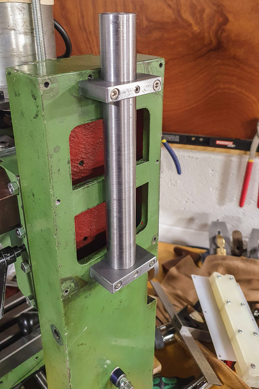
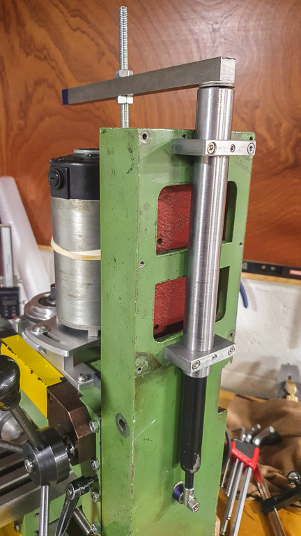
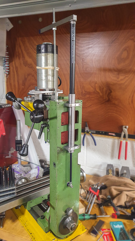
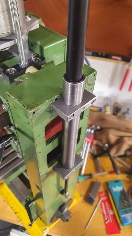
Here you can see the spring loaded arm that balances the weight of the (now stripped) head. They're apparently not particularly even in the force they produce, so I planned to remove it and add a gas strut instead:

10.jpg


Many more images coming soon...
 
Previous owner had no business being near that! 2 rocks to rub together would be his level I reckon.
 
Time to make pulleys for a belt drive conversion.

I got some 6082 T6 aluminium to make the small pulley that will fit onto the motor shaft:

11.jpg


12.jpg


13.jpg


14.jpg


The larger pulley (for the spindle) was made from two pieces; otherwise I'd have had to remove a huge amount of material from large diameter stock.

First the large section for the pulley itself:

15.jpg


Then the smaller section:

16.jpg


The two were joined with some bolts:

17.jpg


Steps for the two pulley diameters:

18.jpg


Pulley grooves:

19.jpg


Central section bored out to fit the spindle:

20.jpg


Lacking any keyway broaches, I ground some cutters from steel:

21.jpg


And slotted the large pulley:

22.jpg


Then the small pulley:

23.jpg


More later...
 
Previous owner had no business being near that! 2 rocks to rub together would be his level I reckon.
To be fair, the motor problem might have been caused (by me) in transit, and when I looked into the internal gearbox issue with the SX2 clones I found it's a very common occurrence - hence the number of belt drive conversions!
 
With the belt drive conversion I needed a new way to mount the motor, using a swinging arm so the belt can be changed/moved/tensioned. First a prototype in plywood:

24.jpg


25.jpg


That seemed to work well, so onto a version from aluminium. Ignoring the warning sign, I fired up the CNC machine:

26.jpg


Basic parts before finishing:

27.jpg
 
The next steps were stripping down the rest of the frame; including all the dovetails on the axes:

28.jpg


29.jpg


And removing the old Z axis lifting mechanism:

30.jpg


Having removed the spindle for the old geared drive I would be left with a hole at the top and bottom of the head casting, so a template for a new cover was made:

31.jpg


32.jpg


Copied in HDPE plastic using a template following bit on the router table:

33.jpg


Bottom of the casting:

34.jpg


New cover fitted (with old cover in the background):

35.jpg


And the top:

36.jpg


Finally with the new pulley fitted. At this point I'd also drilled a pair of holes near the bottom of the pulley for a locking pin:

37.jpg
 
By this point I'd done a final clean up of the external parts, so it was time to begin putting the machine back together. First job was finishing the new motor mount, and also installing a locking pin holder (with a temporary, overly long, bolt):

38.jpg


39.jpg


Motor plate on the bottom of the motor, also showing the smaller pulley:

40.jpg


Fitted:

41.jpg


At some point I may make a knob for the motor mount screw (so the belt can be changed without using an allen key), but it's fine for the moment:

42.jpg
 
The next job was working out how to install a gas strut (for supporting the weight of the head). Little Machine Shop in the US offer a gas strut kit, and their strut is rated for 35lbs. 35lbs is 15.9kg (which seemed ballpark ok for the head on my machine), so I placed an order with SGS Engineering here in the UK. Their struts are ordered by Newtons, so I went for 155N as the closest "round number". The model I ordered is the GS8-18-280-310; though perhaps the next shorter version would have worked too.

Measuring out:

43.jpg


A block was drilled and tapped into the top of the head:

44.jpg


The rear of my machine has a thin metal panel, which I replaced with a sheet of HDPE plastic (assuming the strut might rub on the sheet):

45.jpg


On some of the newer SX2 clones the electronics box is on the rear of the machine and the top of the casting is open instead. As such, the strut can be mounted further forward (towards the head). The vertical column on this mini mill has a solid top, and there's a rib running through the middle of the inside towards the lower half. As such, it would've been difficult to put the strut inside the column.

With the strut being further away from the head I found that at the top of the stroke, the strut wants to bend out in the middle (away from the rear of the column) when the head is lowered. To prevent this I put together a "box" with some more HDPE to contain the strut and ensure it only runs vertically:

46.jpg


That seems to work pretty well. I have an alternate idea for the strut, but that's a job for the future.
 
Last set of "historical" updates.

One kit of parts for a mini mill:

47.jpg


Slowly going back together:

48.jpg


49.jpg


Time to look at the electronics. Neither bulb on the front panel appeared to be working, so time for a look:

50.jpg


The green bulb was dead, but I'd ordered a spare from Arc Euro Trade so I soldered that on. The orange/yellow bulb turned out to be OK, but one of the wires had broken off, so that was soldered back on too:

51.jpg


Having put everything fully together for the first time, a problem was evident. When the motor is swung back to tension the belt, the brush holder on the rear hits the rod supporting the head:

52.jpg


The rod could be moved back a few mm, but for the moment I just rotated the motor so the brush holders are on the sides. It means the cable now faces forward, but a cable tie or band should fix that:

53.jpg


And finally, all together, with a collet holder and bit:

54.jpg


That's about four months of work, on and off.

I have now done a bit of milling (aluminium and mild steel) and it's gone pretty well. Lots still to tune, but the machine appears to be working well.
 
Updates...

I finally got round to the "proper" solution for supporting the gas strut. Two pieces of mild steel were drilled and then bored:

57.jpg


A 12mm end mill was used to clean up the slot:

58.jpg


The ends (with the tapped holes) will later be cut off, and holes drilled in the top for attaching to the mill body:

59.jpg


The gas strut will ride inside a metal tube, but the gap between the strut and the mill body required a small flat to be milled onto the tube:

60.jpg


Parts cleaned up and ready for fitting:

61.jpg


A reminder of the current plastic guide for the gas strut:

62.jpg


All removed:

63.jpg


New system fitted. Grub screws are used to position the height of the tube:

64.jpg


Fully lowered:

65.jpg


Fully raised:

66.jpg


Another angle:

67.jpg


Early days yet, but it feels very solid, and the movement is really smooth - the head can be raised and lowered the whole travel with just one finger spinning the arm on the right side of the mill. I may blank off the remaining open section at the back of the mill at some point, and obviously clean up the over sized rod and metal bar that attach the gas strut to the head.

What's next? A taster...

68.jpg
 
VERY nice work sploo.
Thanks. It works surprisingly smoothly; but don't look too hard at the machining quality of the parts!

Certainly I'm learning the limits of the mini mill and mini lathe, and appreciating why the "proper" machinery is usually 10 to 20 times the mass.
 
Which collets did you buy? I have the same mill and would like to use collets rather than a chuck.

When I got mine the entire motor was loose, you could rock the top of the motor at least 10mm, resulting in a lot of noise. All the gears were is surprisingly good condition though.
 
Which collets did you buy? I have the same mill and would like to use collets rather than a chuck.

When I got mine the entire motor was loose, you could rock the top of the motor at least 10mm, resulting in a lot of noise. All the gears were is surprisingly good condition though.
IRC It's an ER20 collet adapter with an MT3 taper (and importantly, M12 drawbar thread). I also bought a set of imperial and metric ER20 collects. All from banggood.

ER20 only goes up to a maximum of 13mm, so I also bought a 16mm MT3 collet for a cutter I have with a 5/8" shank (though it may be too big for that little mill).

You're lucky with the gears though; I understand they're essentially a "consumable" component. If you're fortunate you break one on the top. If you break the internal gears you're in for a very long day. Given that the internal gears were lunched on my unit I opted to do the belt drive conversion.
 
Excellent work. With the skills people have on here I can’t help but wonder if this group couldn’t design and build its own set of community machines and then have them manufactured....

A couple of questions about the gas strut. Can you mount them either way up or does the cylinder have to go on top? Is the force applied in a linear fashion, I.e. is the resistance the same when fully extended or compressed? I’m looking at ways of supporting a Startrite drill head and a gas strut is one option....

thanks.
I think generally they're intended to be used with the thinner rod facing upwards, but it doesn't actually matter. However, the advice for mills is that by facing them downwards there's less risk of it clogging up with chips or dust.

The force is surprisingly linear (unlike the spring loaded arm that was originally fitted). As noted; I can raise and lower the ~16kg head on the mill by spinning the rotating arm with a single finger.

Work out the weight of your drill head in kg and multiply by 9.81 to get a suitable force value in Newtons (e.g. with my 16kg head I went for a 155N strut as close enough).
 
Thanks. It works surprisingly smoothly; but don't look too hard at the machining quality of the parts!

Certainly I'm learning the limits of the mini mill and mini lathe, and appreciating why the "proper" machinery is usually 10 to 20 times the mass.

Yup, it really IS true about "price". With my "budget" (!) one of the things I'm still having to learn (lathe only, me, no mill) is that you really DO need to appreciate how the light-weight components lead to inherent lack of "real" rigidity. But if one isn't in a hurry (what's 4 x 10 mm cuts against 1 x 40 mm cut?) is that it's "only" my time! No real problem, and I don't have the space for "proper" machines anyway. :)
 
Back
Top