


Chems
Established Member
A bit of a different one. I've been a bit unhappy with my last 2 router tables, either the table or the router. So this time around I'm doing it properly. First I wanted a cheap powerful router so got this for £60something:

Which seems to be a very nice router, coupled with a extended collet. Soft start, very powerful nice functions. The first job was to remove the springs, couldn't find a way to take them out of the top, so yanked them out through the bottom which was great fun. There aren't many pictures of this bit.
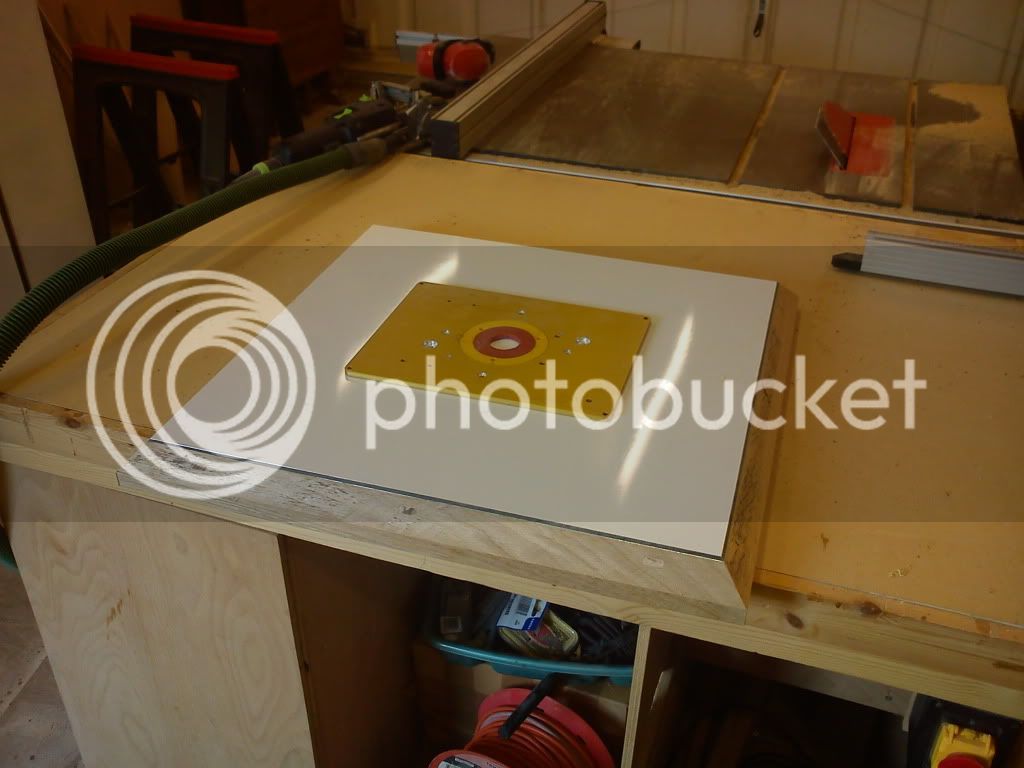
Onto the table, I used a sign making material for my top, its a aluminium composite, .3mm ally with plastic sandwiched between. Glued to an old kitchen worktop using mitre fast, made sure it was nicely flat this time as last time I used some fireback it had some bobbles in it. Chamfered the edges to ensure not sticking as things get caught on the edge of the table, a problem with previous ones:
This has since been put into a nice oak veneered router cabinet, odd for me, no photos! Next I removed the fine height adjuster from the router, and used that nice channel left to put a M12 threaded rod through. On this I drilled through a bolt to captivate that at the top within the bottom of the base. And then use a bolt at the top of the adjuster tunnel. So when the rod turns the bolt lifts the router up and down.
I could just hook it up to like an old drill or multi tool which I thought I might originally, but I decided to go a bit further. What I'm after is having 1 button to do a +1mm another to do a -1mm and another 2 to do fully up and fully down. Perhaps a 10mm up 10mm, the possibilities are endless! The problem with a standard DC motor is they just spin theres no accuracy, so I decided to use a stepper motor which can be controlled to the degree. This particular one has 42 steps at 1.7 degrees.
After a bit of soldering and learning Arduino (google it if your a tech lover) I finished doing a quick program to get it working.
Red Buttons = +1mm
Green = -1mm
White = All the way up
Blue = All the way down
http://www.youtube.com/watch?v=n2djhhEnGqU
The bit to note here is when pressing the white and blue buttons at the end the masking taped shaft goes exactly back to where it was which is the idea of the extra work involved in using the stepper motor vs normal.
And heres the basic code, I'll next implement a counter so it knows where it is so it can do the fully up fully down without limit switches.
So next up is to remove the tiny motor, and couple it with a powerful motor and controller. The problem there was working out how much torque it was taking to turn and lift the 9kg router using just a standard threaded rod. So I bought a proper measuring torque wrench after the only torque wrench I had its lowest setting was 5 feet pounds. The new one didn't even register so I'm just going to go with a 4nm stepper and hope for the best which looks like this:

So sorry for the long post with little saw dust, but hopefully interesting to others and a future alternative to:
http://www.mlcswoodworking.com/ordersta ... rlift.html
Which seems to be a very nice router, coupled with a extended collet. Soft start, very powerful nice functions. The first job was to remove the springs, couldn't find a way to take them out of the top, so yanked them out through the bottom which was great fun. There aren't many pictures of this bit.
Onto the table, I used a sign making material for my top, its a aluminium composite, .3mm ally with plastic sandwiched between. Glued to an old kitchen worktop using mitre fast, made sure it was nicely flat this time as last time I used some fireback it had some bobbles in it. Chamfered the edges to ensure not sticking as things get caught on the edge of the table, a problem with previous ones:
This has since been put into a nice oak veneered router cabinet, odd for me, no photos! Next I removed the fine height adjuster from the router, and used that nice channel left to put a M12 threaded rod through. On this I drilled through a bolt to captivate that at the top within the bottom of the base. And then use a bolt at the top of the adjuster tunnel. So when the rod turns the bolt lifts the router up and down.
I could just hook it up to like an old drill or multi tool which I thought I might originally, but I decided to go a bit further. What I'm after is having 1 button to do a +1mm another to do a -1mm and another 2 to do fully up and fully down. Perhaps a 10mm up 10mm, the possibilities are endless! The problem with a standard DC motor is they just spin theres no accuracy, so I decided to use a stepper motor which can be controlled to the degree. This particular one has 42 steps at 1.7 degrees.
After a bit of soldering and learning Arduino (google it if your a tech lover) I finished doing a quick program to get it working.
Red Buttons = +1mm
Green = -1mm
White = All the way up
Blue = All the way down
http://www.youtube.com/watch?v=n2djhhEnGqU
The bit to note here is when pressing the white and blue buttons at the end the masking taped shaft goes exactly back to where it was which is the idea of the extra work involved in using the stepper motor vs normal.
And heres the basic code, I'll next implement a counter so it knows where it is so it can do the fully up fully down without limit switches.
Code:
#include <AFMotor.h>
AF_Stepper motor(48, 2);

void setup() {
  Serial.begin(9600);
  pinMode(2, INPUT);
  pinMode(3, INPUT);
  pinMode(11, INPUT);
  pinMode(10, INPUT);
  motor.setSpeed(500);
}

void fturn(int amount){
      motor.step(amount, FORWARD, MICROSTEP);
}

void bturn(int amount){
      motor.step(amount, BACKWARD, MICROSTEP);
}

void loop() {
  int btn_one = digitalRead(2);
  int btn_two = digitalRead(3);
  int btn_three = digitalRead(11);
  int btn_four = digitalRead(10);


 if(btn_one == HIGH){
    fturn(1);
    Serial.print("Button 1 Pressed: ");
    Serial.println(btn_one, DEC);
 }

 if(btn_two == HIGH){
    bturn(1);
    Serial.print("Button 2 Pressed: ");
    Serial.println(btn_two, DEC);
 }

  if(btn_three == HIGH){
    fturn(20);
    Serial.print("Button 3 Pressed: ");
    Serial.println(btn_three, DEC);
 }

  if(btn_four == HIGH){
    bturn(20);
    Serial.print("Button 4 Pressed: ");
    Serial.println(btn_four, DEC);
 }

}
So next up is to remove the tiny motor, and couple it with a powerful motor and controller. The problem there was working out how much torque it was taking to turn and lift the 9kg router using just a standard threaded rod. So I bought a proper measuring torque wrench after the only torque wrench I had its lowest setting was 5 feet pounds. The new one didn't even register so I'm just going to go with a 4nm stepper and hope for the best which looks like this:
So sorry for the long post with little saw dust, but hopefully interesting to others and a future alternative to:
http://www.mlcswoodworking.com/ordersta ... rlift.html

