Homemade belt sander / linisher

UKworkshop.co.uk

Help Support UKworkshop.co.uk:

This site may earn a commission from merchant affiliate links, including eBay, Amazon, and others.

DennisCA

Established Member
Joined
26 Apr 2014
Messages
1,058
Reaction score
211
Location
Finland
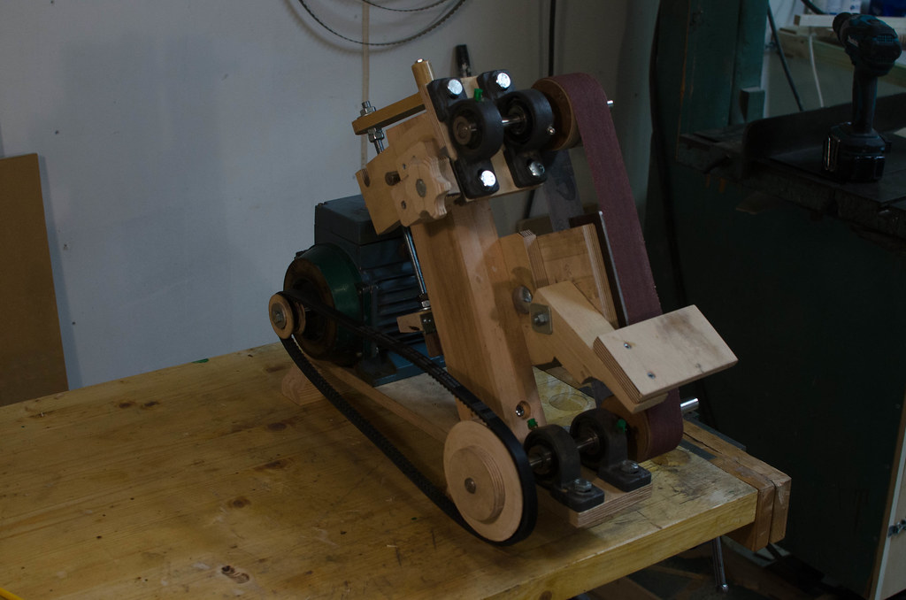
Well, kinda. I really liked the concept of the sorby pro edge sharpening system. But the price wasn't very agreeable and I like homemade tools. The design isn't mind but copied from John Heisz 's forums, by another user called Pekka.

25537853885_df05976d0d_b.jpg


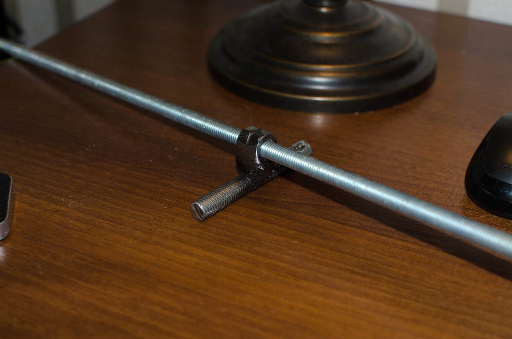
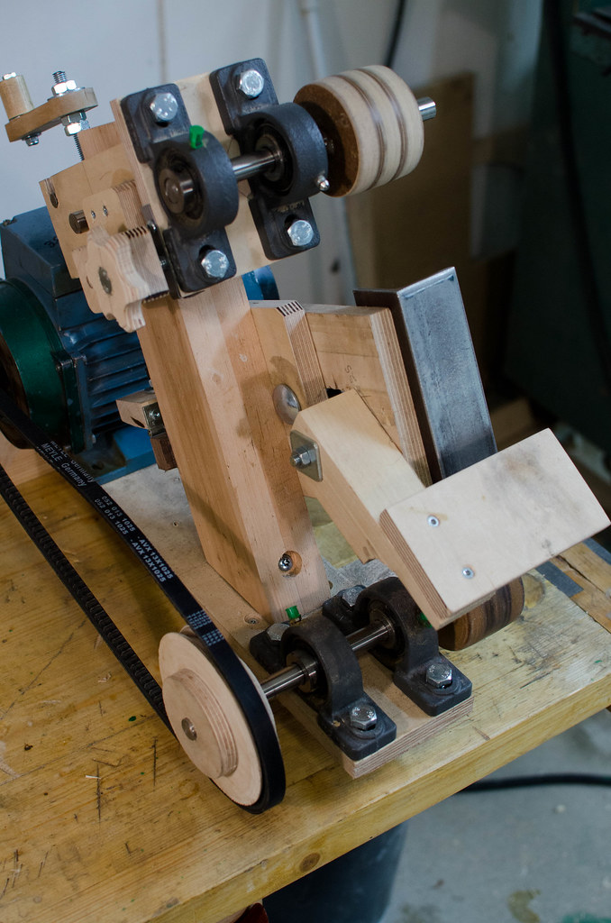
Got some extra bolts, and replaced the tracking adjusting rod with a bolt and knob:
25242237740_8e4baeceaf_b.jpg


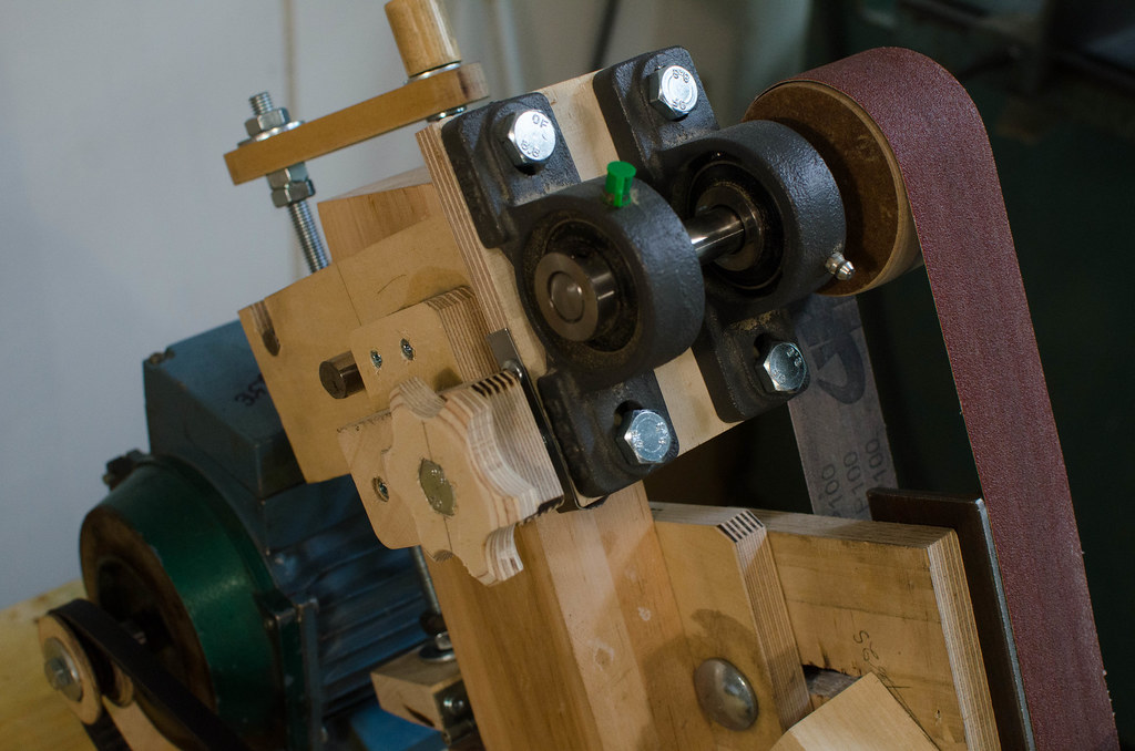
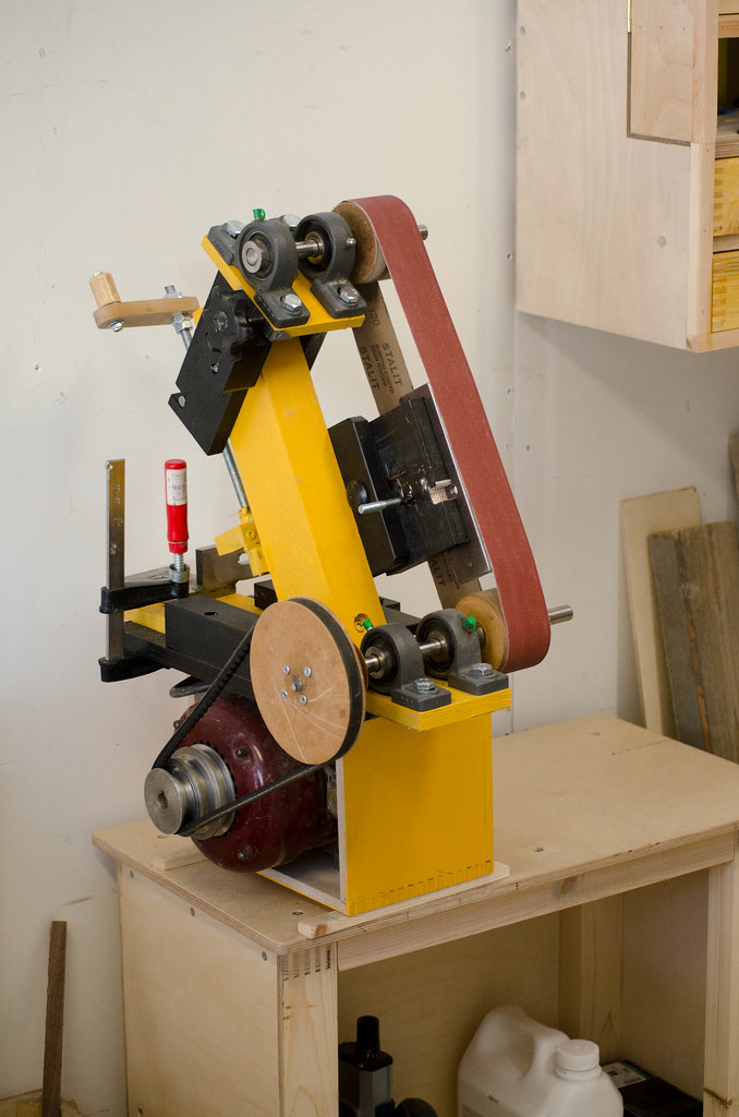
The tensioning mechanism works real nice and I calculated that I can take up to a 50x1000mm sanding belt. So this sander can take belts from 790mm (sorby belts) up to 1000mm long, a span of 210mm.
25242247710_af56a9887f_b.jpg


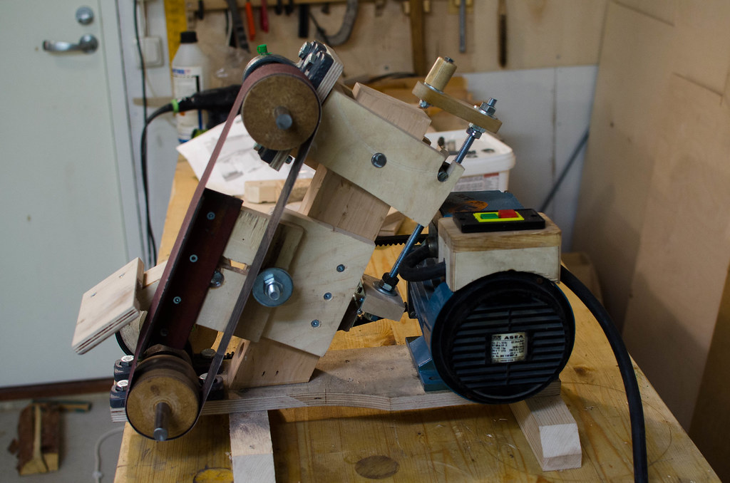
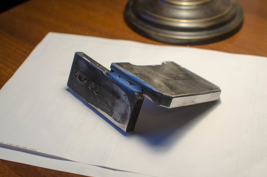
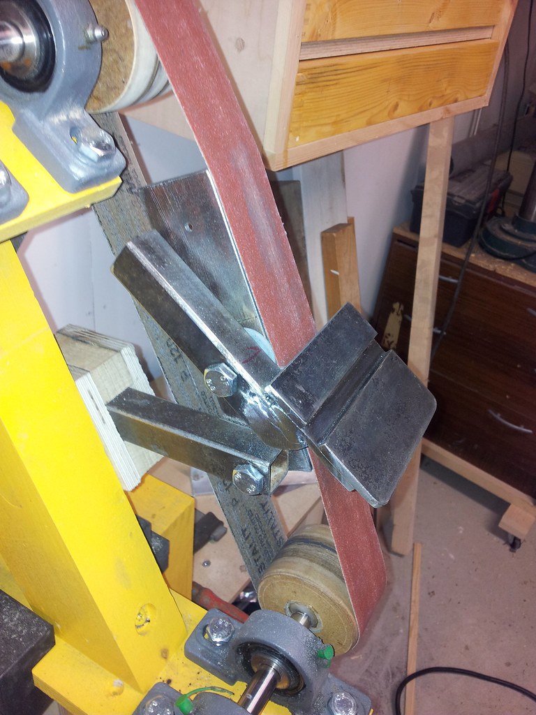
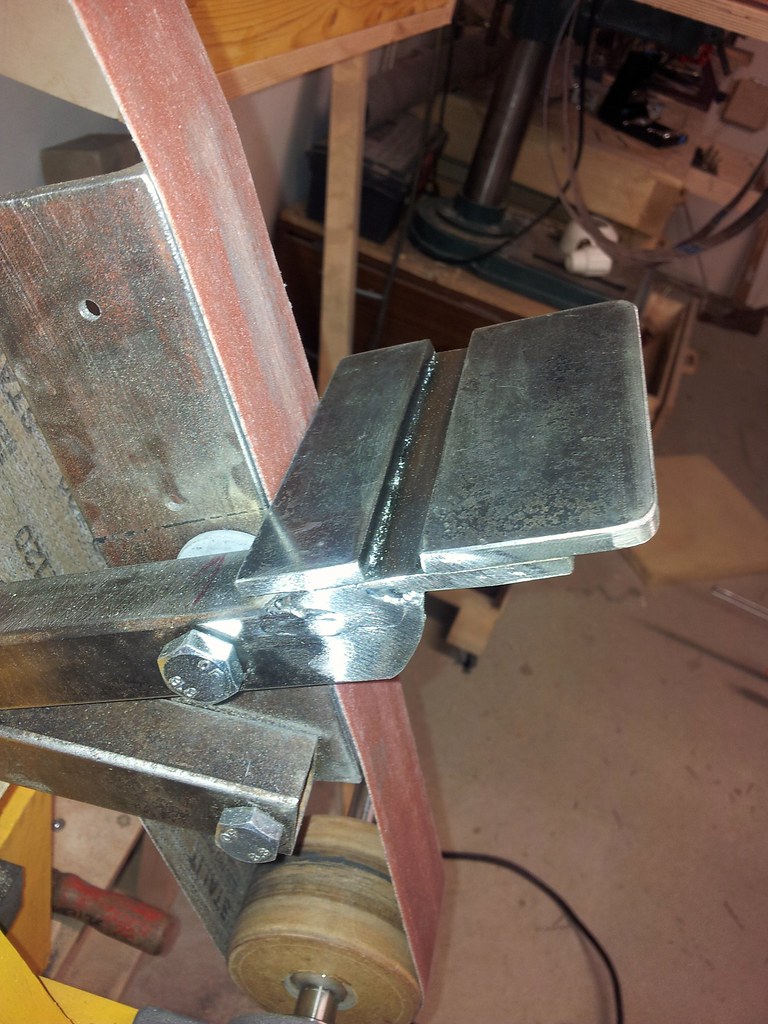
Because of this wide span of possible belt sizes, the upper and lower wheels will be in different positions depending on belt length. So I made the platen so it could be moved and adjusted for various belt lengths.

25537886545_2ae1b0cf2e_b.jpg


The platen is made from a piece of angle iron that I literally found rusting under my deck this summer (some of the house builders must've left it behind) and had forgotten about, just the right size too.

Next step is to paint it, I am thinking black and yellow. The belt speed is not very fast so the dust mainly falls straight down. Some more fiddling with the tool rest is needed too.
 
Thanks, one of the things I believe I need to chance is the tool rest, would be better if I could move the pivot point as near the belt as possible.
 
Nice job Dennis. It might be an idea for you to route a slot in the table for mounting jigs? That's what I've done with my sander. I've also mounted a round shaft for using a jig to sharpen wood turning gouges.
 
Looks really good DennisCA, thanks for posting.

Yet another item to add to my "gettaroundtoit" list!

=D>

AES

Edit for P.S. Is the motor/pulley drive belt a toothed belt? If so was there a special reason, or was it just a question of "what I had lying around" please?
 
Thanks, all :)

woodpig":1njohhyk said:
Nice job Dennis. It might be an idea for you to route a slot in the table for mounting jigs? That's what I've done with my sander. I've also mounted a round shaft for using a jig to sharpen wood turning gouges.

That's definitely the plan, but the table was the part I had thought through the least and I am already replacing it. I am building a metal table instead to make it sturdier. I'm new to working with metal, I cut up some pieces of 12mm steel I had and shaped it as best I could. Still working on the slot on the side, that way I can always keep the table near the belt regardless of angle. Not quite sure how I will mill a slot in the top but I'm sure I'll think of something.

25558677415_8212f65ae2_b.jpg
 
This is the table I fabricated from a couple of pieces of steel fixed together with two M8 bolts.
_IGP2941.jpg
 
AES":35qizgyf said:
Edit for P.S. Is the motor/pulley drive belt a toothed belt? If so was there a special reason, or was it just a question of "what I had lying around" please?

It was just what I found in the local store that was in the right length. I understand they are better for making a tight bend though.
 
woodpig":mzfrjf1h said:
This is the table I fabricated from a couple of pieces of steel fixed together with two M8 bolts.
_IGP2941.jpg

are the slots in the table milled?
 
Yes Dennis they are milled. Another option though is to bolt two strips of metal on top of another piece leaving a gap between them leaving a slot.
 
woodpig":3j085pik said:
Yes Dennis they are milled. Another option though is to bolt two strips of metal on top of another piece leaving a gap between them leaving a slot.

That's what I've been considering. But after going through the options it seems it'd be best to JB weld or solder the plates together. Real welding would probably warp it, screws and tapping is imprecise (or so I was told).
 
Screws on there own wouldn't be ideal. It would be better to use dowel pins and screws.
 
Well the upper portion pivots up and down on a piece of 15mm axle, to force the rear part down and thus the front part up, I made this thing:
24847262774_34925c8d02_b.jpg


I welded some M10 nuts to a piece of metal, then I welded that to a threaded rod to get this cross shape.

25242247710_af56a9887f_b.jpg


I made hooks in the rear of the pivoting part for the short rod to hook into, and then using a hinge, some washers and jam nuts I made a pivoting base that retains the long threaded rod. By spinning the rod now I can force the back down and thus tension the rod. I used a drill to start with, but then fitted a turn crank.
 
If I were making one I would be tempted to try to make a twin belt machine, to run course and fine grits without a belt change.
 
I have updated this machine a bit, new motor and mount and step pulleys for various speeds.
26599926880_b90c67b1f8_b.jpg


And today I finished a new table and a better way of mounting it and the backing plate:
26512288563_269b0722cf_b.jpg


27047714891_3bd2ee02f7_b.jpg


Plug welded three pieces of steel together to make this. That stuff in the slot in the last picture is just metal from grinding.
 
Back
Top