


I have been looking around for a small table saw for my single car garage workshop. I considered a few brand new models that are popular here but as I have already rebuilt a Sedgwick Planer thicknesser http://www.ukworkshop.co.uk/forums/sedgwick-pt255-strip-down-and-rebuild-t66864.html, I decided that I wanted to try and find another older British machine. The old Wadkins are fantastic machines but much too large for my single garage. I wanted a compact footprint similar to the TS200 / Kity 419 but I found it really difficult to identify a smaller British industrial tablesaw that was around this sort of size. Doing a bit of research, I thought the Startrite TA 145/156/175 series was a possibility.
I picked this particular one up from well known auction site for £100 + another £63 inc vat to get it delivered. It was described as a single phase model that was functional with a few items missing. Althought the saw was too far away from me to go and look at, at the price I was prepared to bid, I decided to take a chance as single phase machines are a bit harder to get around this price.
This was the machine as delivered.
The Startrite TA145 It is a very nicely made and compact table saw with plenty of cast iron and good quality steel. Not in the Wadkin league for construction but a good workshop saw that should manage to do everything that I need it for. It will take up to a 235mm diameter saw and should just about manage a 75mm depth of cut. Table size is around 56cm by 59cm wide.
Front
View attachment 1
Right hand side

Left hand side
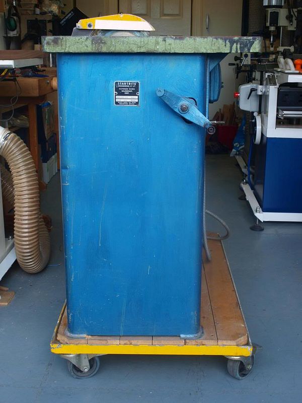
When delivered, it ran, albeit a bit noisy and rattled but otherwise I was really happy with the purchase as all the basic elements were fine and overall despite missing a few bits, it was in far better condition than the Sedgwick Planer Thicknesser I rebuilt!
It came bolted to a very sturdy stand. the problem was that the stand was rectangular and as well as taking up more space than I wanted, it raised the height too much for me to work comfortably.
Original stand
I have "previous" for building stands, see post here: build-your-own-simple-mobile-machine-base-with-photos-t67483.html but I needed a completely different type of stand to allow the saw to be moved around in any direction easily.
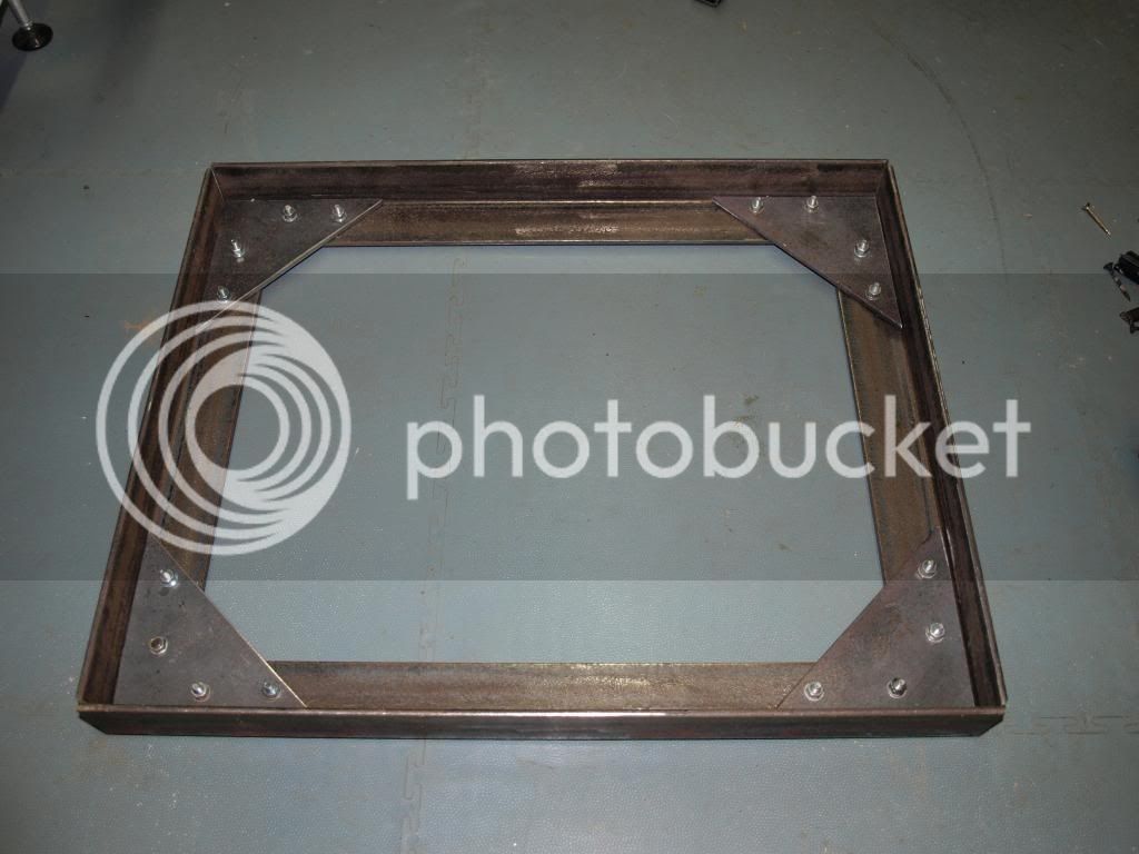
I started by cutting some 50mm angle iron and bolting it together for my local blacksmith to weld
Top
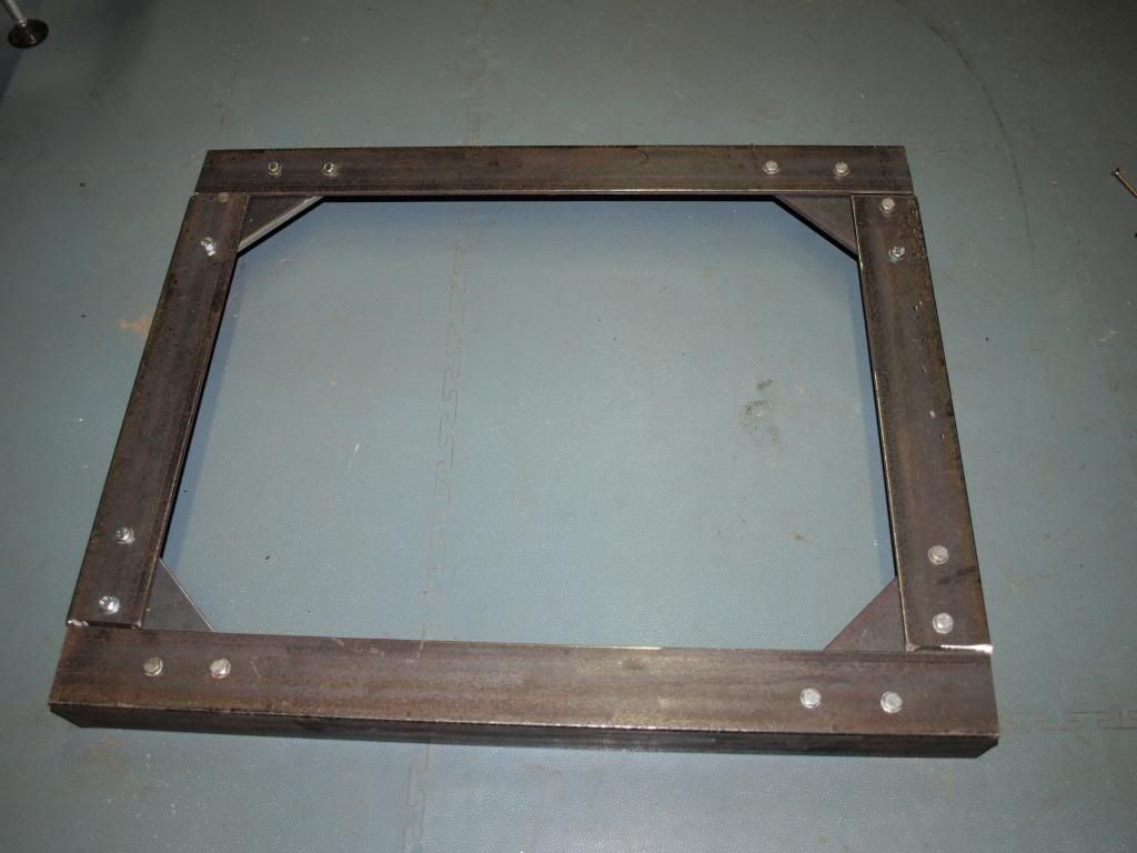
Bottom
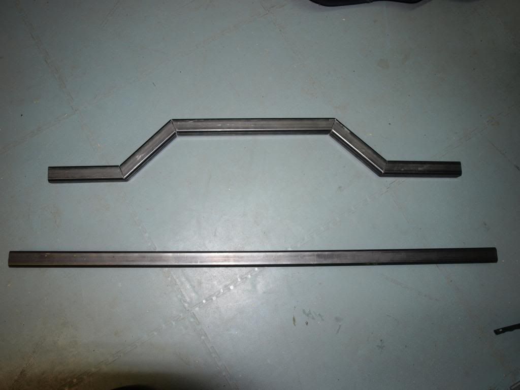
One of the two outrigger legs, cutting some 30mm box section like so with a hacksaw
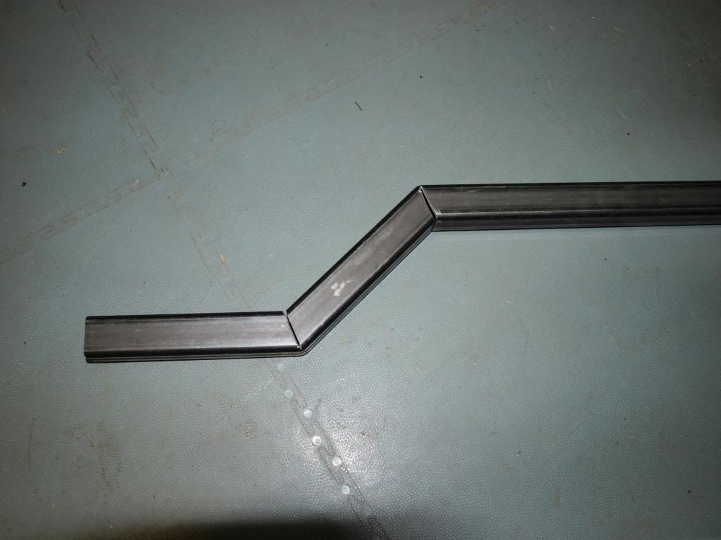
The next photo shows before and after cutting and bending
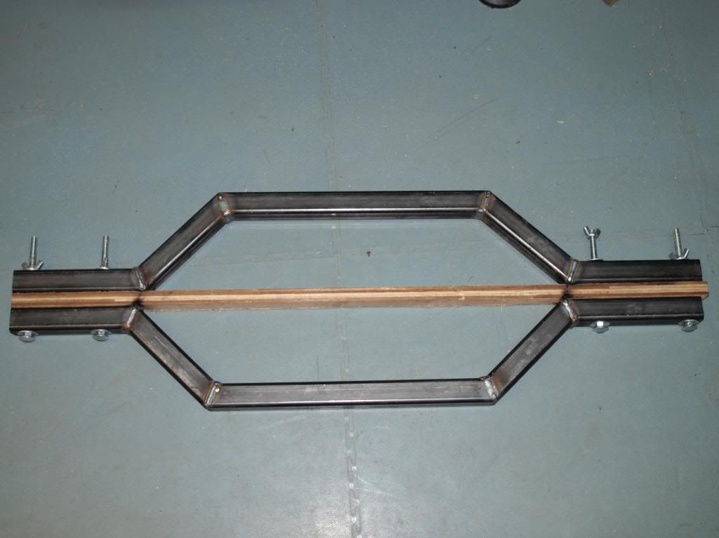
And then temporarily bolted together to a plywood strip to allow them to be welded in the correct shape
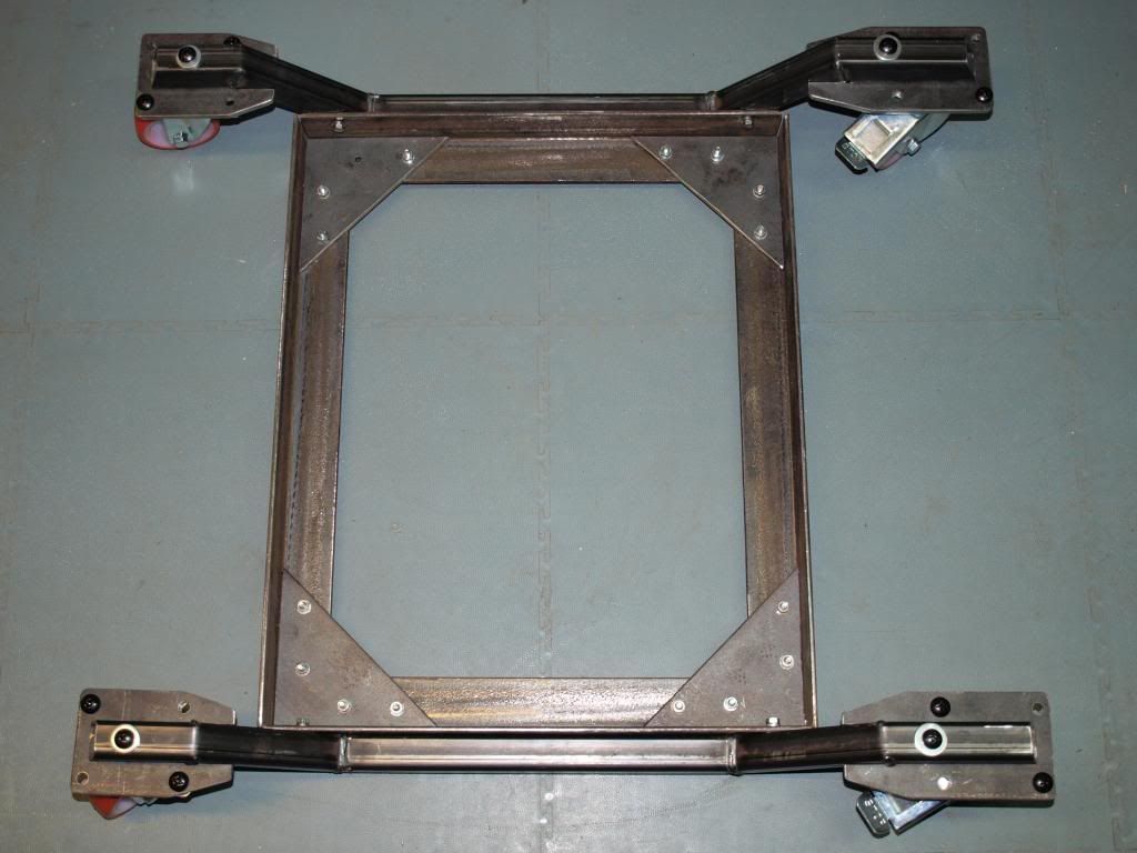
I then made four flat plates and bolted everything together to try the table saw stand out before it was taken to get it welded up
Front
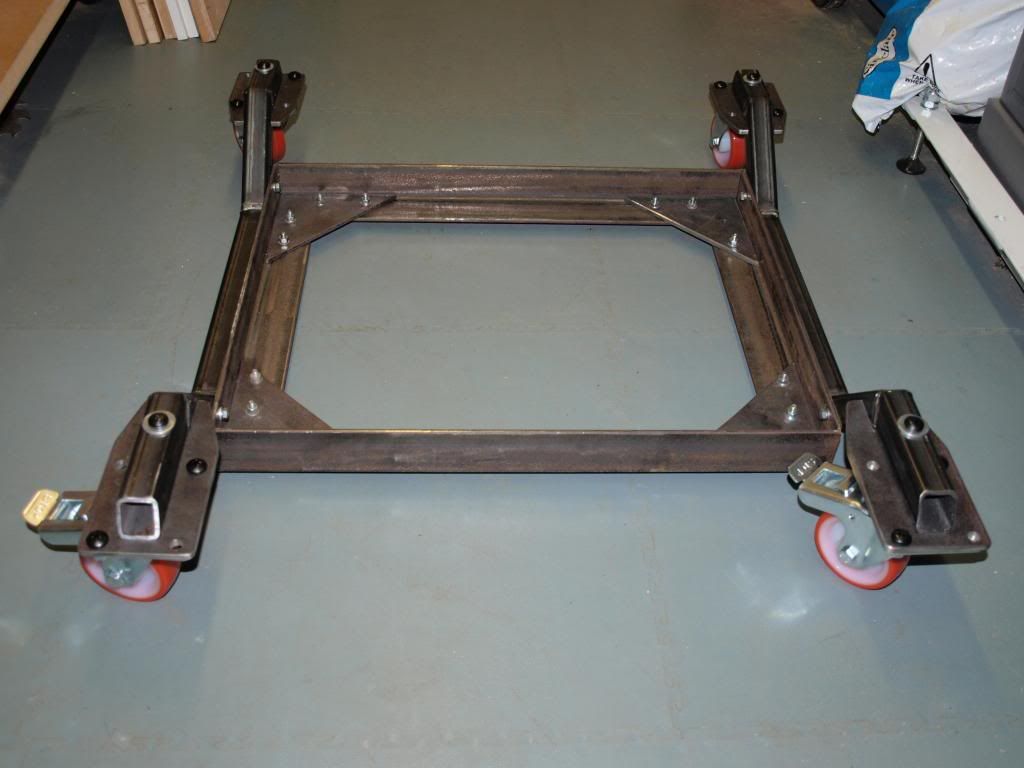
And top view
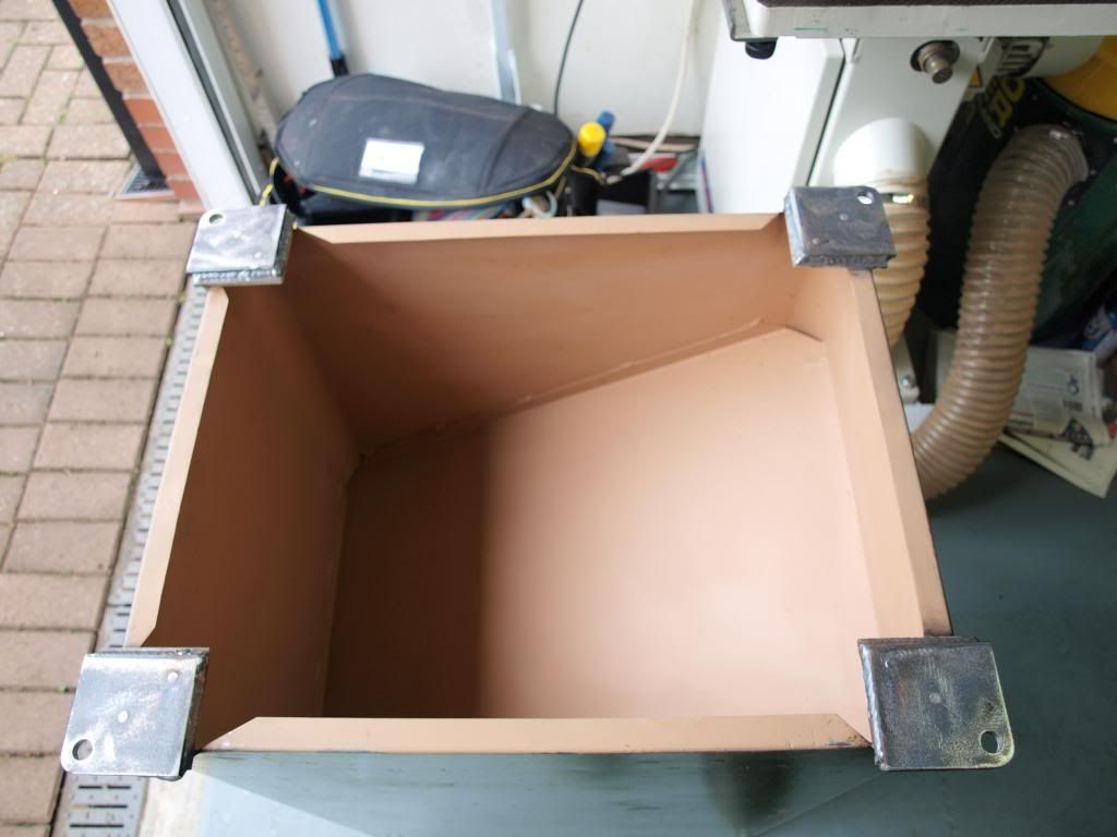
Now some TA series saws have mounting holes in their feet to allow them to be bolted down but my version had only enough area in the feet to locate screws. I needed something more substantial, so I made four square plates up to weld to the original feet at the bottom of the sheet metal base. Again, i bolted them in place to ensure they did not move when being welded.
Four plates shown here
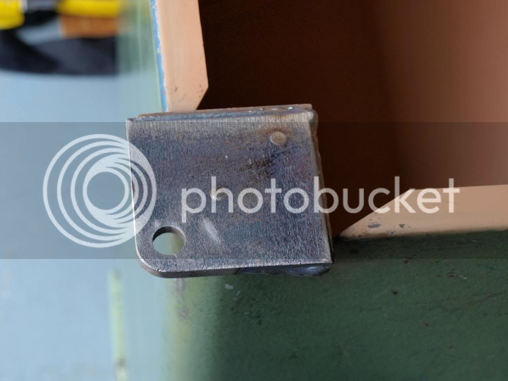
And close up of the underside of one here
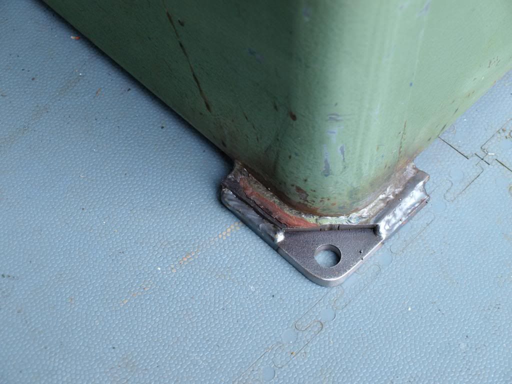
Top side after welding
And bolted temporarily to the finished stand here
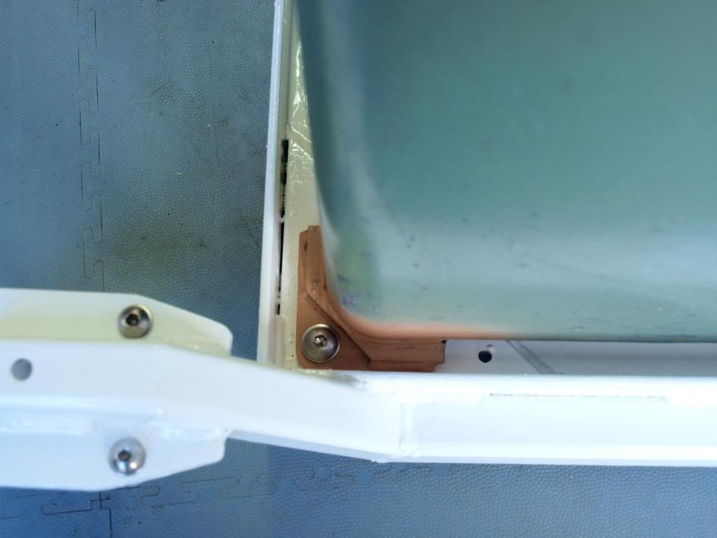
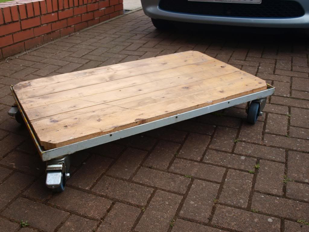
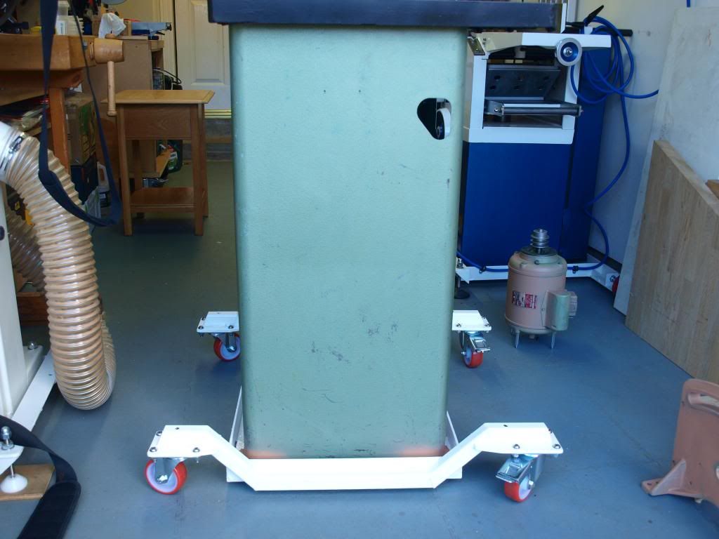
The finished mobile base with the stripped down Startrite TA145 temporarily fitted is shown below
Front
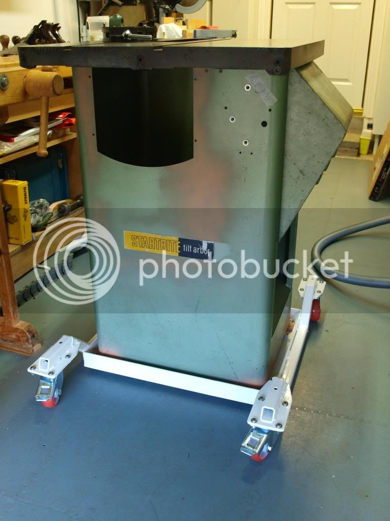
Side
I stripped the poorly applied blue paint off fairly easily with the new "green and friendly" Nitromors but one of the few good things about the new formula was that it left the original Startrite pain untouched. Unlike my Sedgwick, I decided not to strip back to bare metal and will simply be giving it a freshen up with a couple of coats of the correct colour from Alt Saws.
Next step, strip down of single phase Brook Gryphon motor (Updated 21/02/2014)
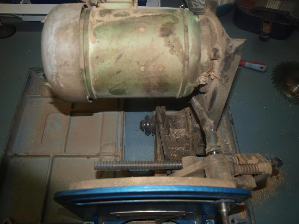
The Gryphon motor was full of fine sawdust, probably as a result of the saw being used for some time without any dust extraction. The next photo shows the Motor before removal from the trunnion/table assembly
The motor can be removed from the trunnion fairly easily by loosening the three cap head socket bolts that tension the two drive belts with an allen key. Being careful to support the end of the motor (its quite heavy!), then remove the three L shaped clamps that hold the motor mounting plate onto the support bracket. The motor mounting plate can then be removed from the front of the motor by removal of the three M8 bolts.
Before removal
Remove the plastic fan cover from the four pointed motor studs by carefully prising it off. It is just a press fit. Then remove the plastic fan blade at the end of the motor VERY Carefully. This fan blade is just a press fit on a splined part of the motor shaft. Don't use a bearing puller to remove it as it will just break. Remove it with two long screwdrivers as wedges under the moulded boss that fits onto the motor shaft.
Th belt drive pulley is keyed onto the shaft and even after removing the grub screw, it was still a really tight fit. I removed it with a bearing puller without any difficulty. A bearing puller can be bought fairly cheaply now and is well worth having if you are going to do machine rebuilds on a regular basis.
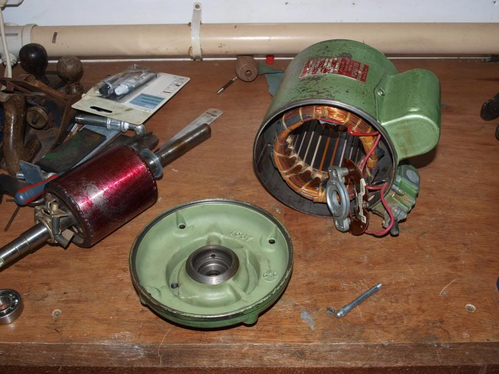
The nuts from the motor end plate can then be removed allowing the whole motor to come apart. I wish I had taken a photograph of the motor before I cleaned out the sawdust but what I can say is that I was surprised that it was still able to turn considering the amount of fine dust in it. With the aid of a soft brush and a shop vacuum cleaner, I was able to remove all the dust leaving the motor in it's component parts as shown below. Note, the bearings came out along with the motor shaft.
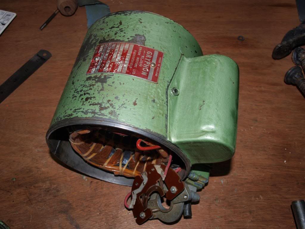
The next image shows the motor casing disassembled with the centrifugal switch attached at the bottom
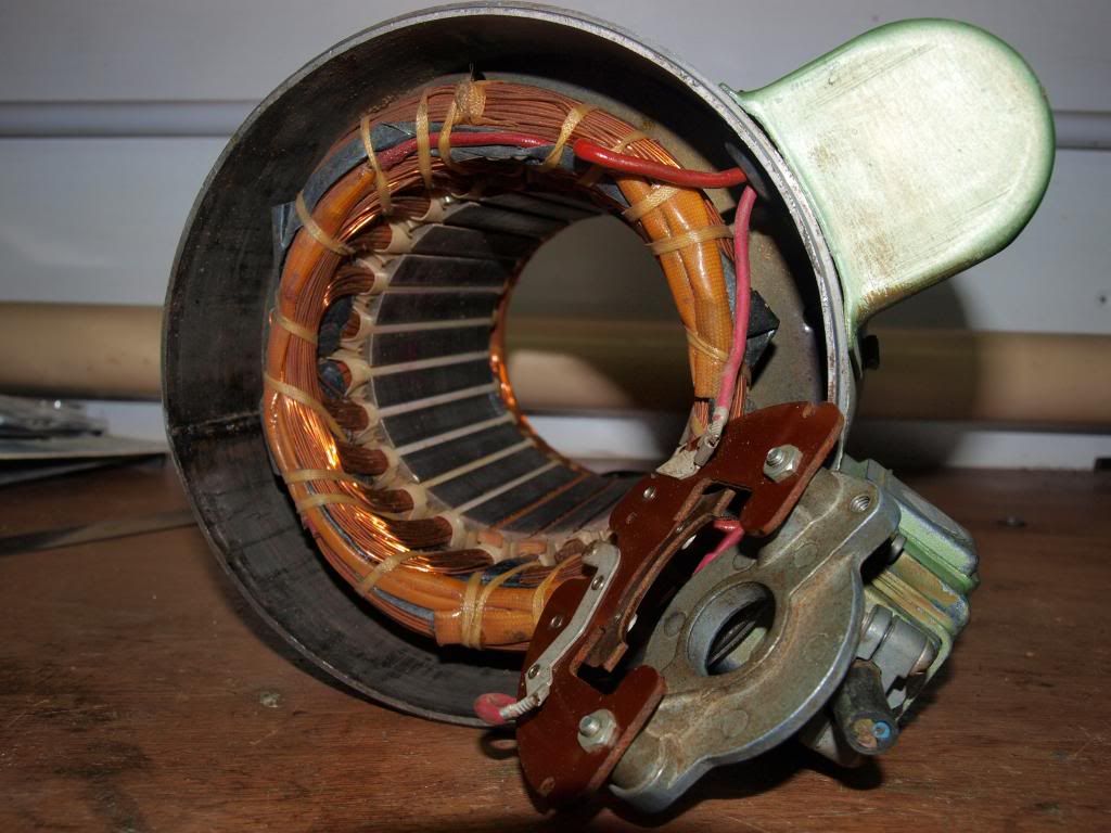
The next image shows the motor casing on the inside with the field coils (Stator). Everything was in good condition with no signs of overheating. These motors are really well made.
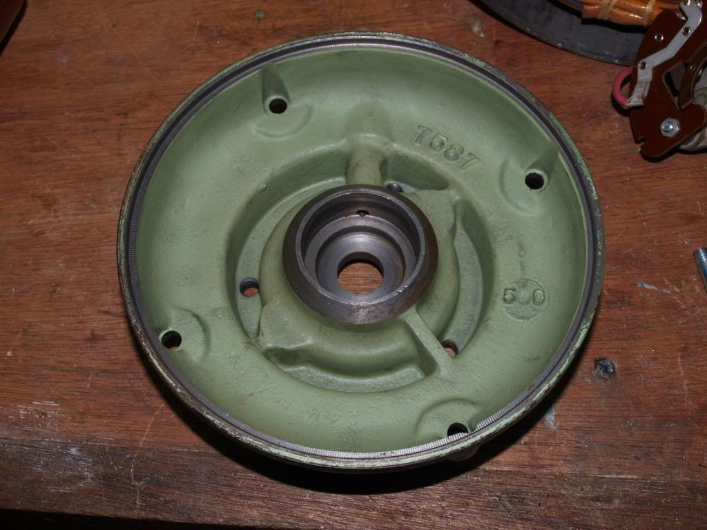
This image is of one of the cast iron motor end plates. The bore in the middle where the bearing was located has a hole at the top allowing grease to be carried down from the grease nipple on the outside
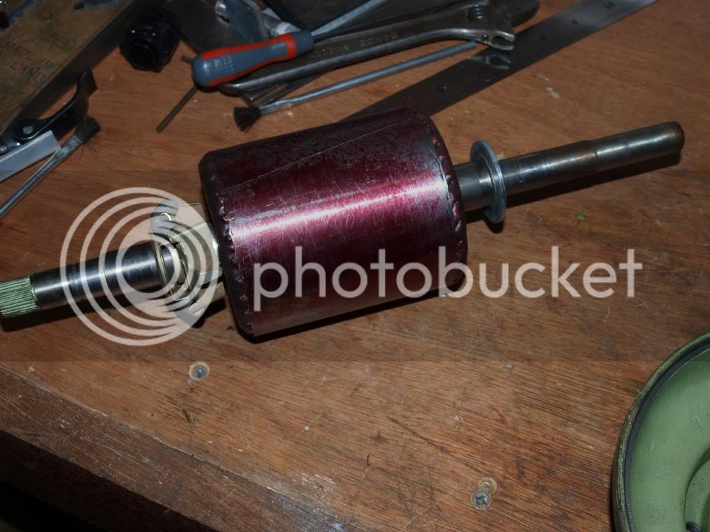
The next image shows the motor shaft (Rotor) with bearing already removed with a bearing puller. Again, there was no wear to the shaft and everything looked fine
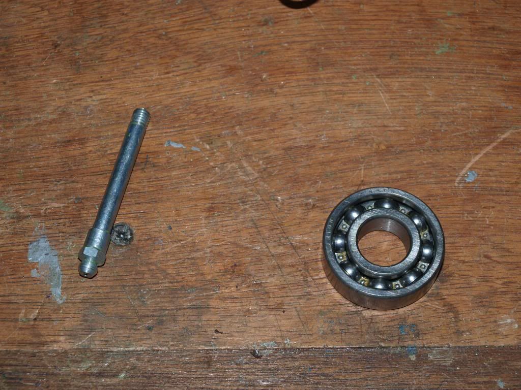
Examining the bearings, there was a little bit of wear and although they were probably still serviceable, I decided that as the motor had been stripped down to this extent, I would replace them with good quality sealed SKF replacements.
Image of bearings on removal below - the original bearings shown are open cage without any grease seals and were originally installed with a grease tube
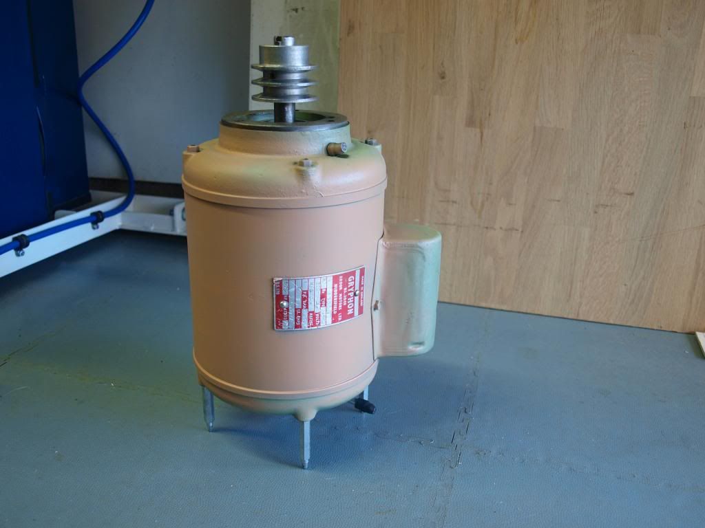
The next image shows the motor rebuilt with new bearings before the fan has been fitted. Check the motor turns freely when assembled. The motor was then temporarily fitted with a cable and a plug and ran smoothly and quietly. A quick coat of primer was applied to the motor after masking of the shaft and pulley.
I will post further updates on the trunnion rebuild shortly
I picked this particular one up from well known auction site for £100 + another £63 inc vat to get it delivered. It was described as a single phase model that was functional with a few items missing. Althought the saw was too far away from me to go and look at, at the price I was prepared to bid, I decided to take a chance as single phase machines are a bit harder to get around this price.
This was the machine as delivered.
The Startrite TA145 It is a very nicely made and compact table saw with plenty of cast iron and good quality steel. Not in the Wadkin league for construction but a good workshop saw that should manage to do everything that I need it for. It will take up to a 235mm diameter saw and should just about manage a 75mm depth of cut. Table size is around 56cm by 59cm wide.
Front
View attachment 1
Right hand side
Left hand side

When delivered, it ran, albeit a bit noisy and rattled but otherwise I was really happy with the purchase as all the basic elements were fine and overall despite missing a few bits, it was in far better condition than the Sedgwick Planer Thicknesser I rebuilt!
It came bolted to a very sturdy stand. the problem was that the stand was rectangular and as well as taking up more space than I wanted, it raised the height too much for me to work comfortably.
Original stand

I have "previous" for building stands, see post here: build-your-own-simple-mobile-machine-base-with-photos-t67483.html but I needed a completely different type of stand to allow the saw to be moved around in any direction easily.
I started by cutting some 50mm angle iron and bolting it together for my local blacksmith to weld
Top

Bottom

One of the two outrigger legs, cutting some 30mm box section like so with a hacksaw

The next photo shows before and after cutting and bending

And then temporarily bolted together to a plywood strip to allow them to be welded in the correct shape

I then made four flat plates and bolted everything together to try the table saw stand out before it was taken to get it welded up
Front

And top view

Now some TA series saws have mounting holes in their feet to allow them to be bolted down but my version had only enough area in the feet to locate screws. I needed something more substantial, so I made four square plates up to weld to the original feet at the bottom of the sheet metal base. Again, i bolted them in place to ensure they did not move when being welded.
Four plates shown here

And close up of the underside of one here

Top side after welding

And bolted temporarily to the finished stand here

The finished mobile base with the stripped down Startrite TA145 temporarily fitted is shown below
Front

Side

I stripped the poorly applied blue paint off fairly easily with the new "green and friendly" Nitromors but one of the few good things about the new formula was that it left the original Startrite pain untouched. Unlike my Sedgwick, I decided not to strip back to bare metal and will simply be giving it a freshen up with a couple of coats of the correct colour from Alt Saws.
Next step, strip down of single phase Brook Gryphon motor (Updated 21/02/2014)
The Gryphon motor was full of fine sawdust, probably as a result of the saw being used for some time without any dust extraction. The next photo shows the Motor before removal from the trunnion/table assembly
The motor can be removed from the trunnion fairly easily by loosening the three cap head socket bolts that tension the two drive belts with an allen key. Being careful to support the end of the motor (its quite heavy!), then remove the three L shaped clamps that hold the motor mounting plate onto the support bracket. The motor mounting plate can then be removed from the front of the motor by removal of the three M8 bolts.
Before removal

Remove the plastic fan cover from the four pointed motor studs by carefully prising it off. It is just a press fit. Then remove the plastic fan blade at the end of the motor VERY Carefully. This fan blade is just a press fit on a splined part of the motor shaft. Don't use a bearing puller to remove it as it will just break. Remove it with two long screwdrivers as wedges under the moulded boss that fits onto the motor shaft.
Th belt drive pulley is keyed onto the shaft and even after removing the grub screw, it was still a really tight fit. I removed it with a bearing puller without any difficulty. A bearing puller can be bought fairly cheaply now and is well worth having if you are going to do machine rebuilds on a regular basis.
The nuts from the motor end plate can then be removed allowing the whole motor to come apart. I wish I had taken a photograph of the motor before I cleaned out the sawdust but what I can say is that I was surprised that it was still able to turn considering the amount of fine dust in it. With the aid of a soft brush and a shop vacuum cleaner, I was able to remove all the dust leaving the motor in it's component parts as shown below. Note, the bearings came out along with the motor shaft.

The next image shows the motor casing disassembled with the centrifugal switch attached at the bottom

The next image shows the motor casing on the inside with the field coils (Stator). Everything was in good condition with no signs of overheating. These motors are really well made.

This image is of one of the cast iron motor end plates. The bore in the middle where the bearing was located has a hole at the top allowing grease to be carried down from the grease nipple on the outside

The next image shows the motor shaft (Rotor) with bearing already removed with a bearing puller. Again, there was no wear to the shaft and everything looked fine

Examining the bearings, there was a little bit of wear and although they were probably still serviceable, I decided that as the motor had been stripped down to this extent, I would replace them with good quality sealed SKF replacements.
Image of bearings on removal below - the original bearings shown are open cage without any grease seals and were originally installed with a grease tube

The next image shows the motor rebuilt with new bearings before the fan has been fitted. Check the motor turns freely when assembled. The motor was then temporarily fitted with a cable and a plug and ran smoothly and quietly. A quick coat of primer was applied to the motor after masking of the shaft and pulley.

I will post further updates on the trunnion rebuild shortly


")


