


siggy_7
Full time tool collector, part time woodworker
Following on from my queries about how to make the joints for glazed doors, I thought I'd write up my project to build a pair of double doors to go on the back of my garage workshop. Currently there is a pedestrian door on one side of the back wall and little space around the side of the house, so the idea is to enable vehicular access to the back garden so I can build a dedicated workshop for woodwork. I've included some details of how I worked out the joint geometry - I make no claims that this is the right way to do it, but the lack of detail on the set-up process meant I worked most of this stuff out myself, so the info may be useful to others.
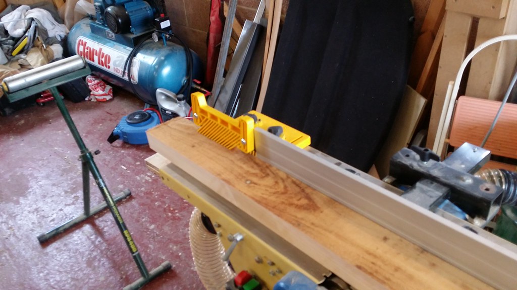
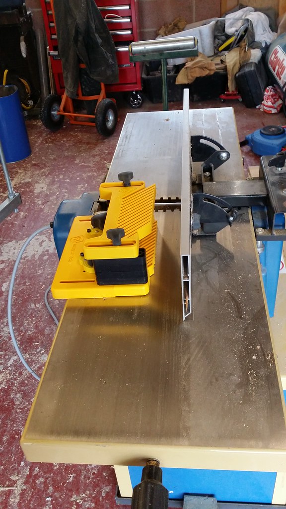
Started out on Saturday morning with a big pile of rough sawn cedar that's been drying in the garage since last summer. Usual ripping and planing operations to get down to the right size of timber. I recently bought some new magswitch accessories which I found useful when planing to help control the longer pieces which are a little over 2m in length - the downward pressure on the outfeed table was particularly useful for surface planing, and it was also much easier squaring the edge off of wider pieces with the featherboards set to push against the fence.
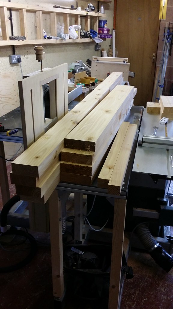
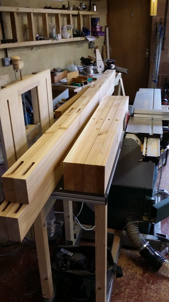
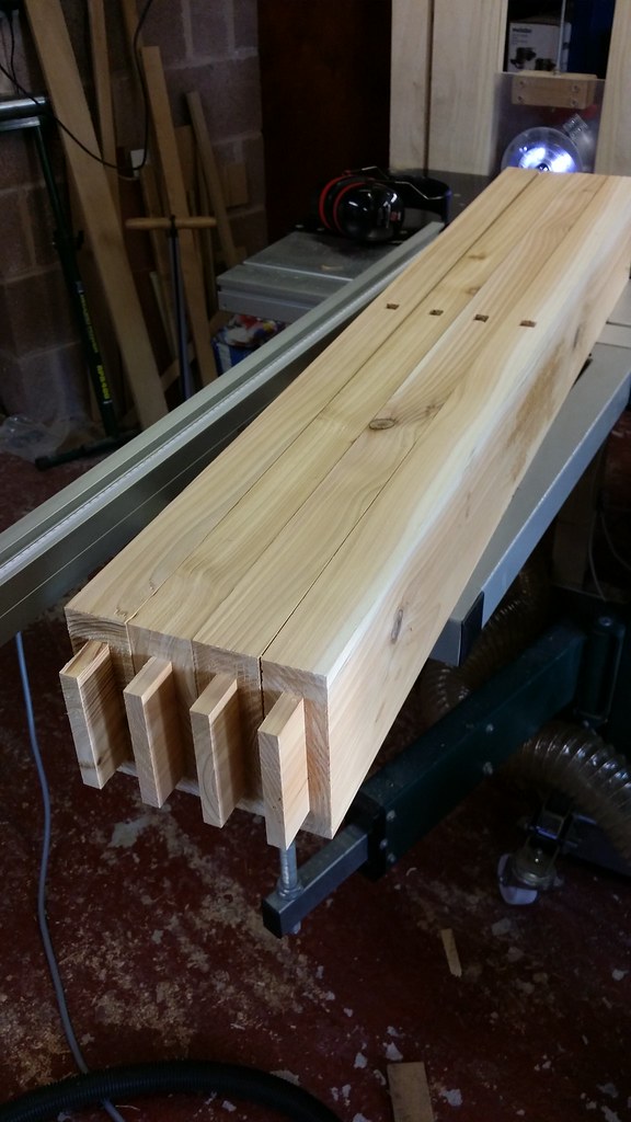
After the first day's work, a nice load of square and straight timber ready for making into the frames.
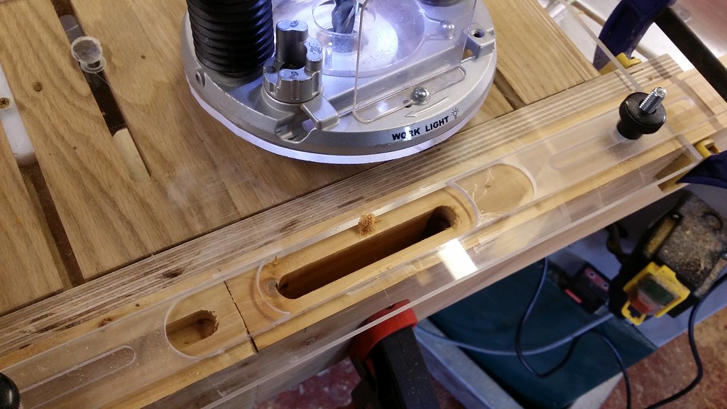
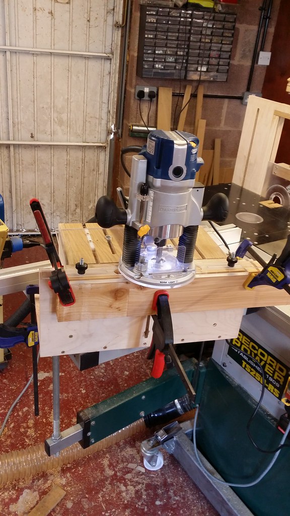
Next up was morticing the stiles and also the rails for the mullions. I built a mortice jig for routing these with - it was inspired by the Trend mortice and tenon jig mainly. There is a perspex plate on the top that supports the router with two sliding dovetail guides made of UHMW plastic, this keeps the plate attached and perpendicular to the body of the jig. There is a 30mm slot routed into the perspex plate for a guide bush to ride left-right in, and adjustable end stops. I made a small gauge from an offcut of the perspex to enable me to line everything up. A 1/2" spiral up-cut bit made really clean mortices.
All mortices cut ready for squaring off with a chisel (which I am terrible at).
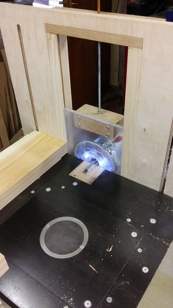
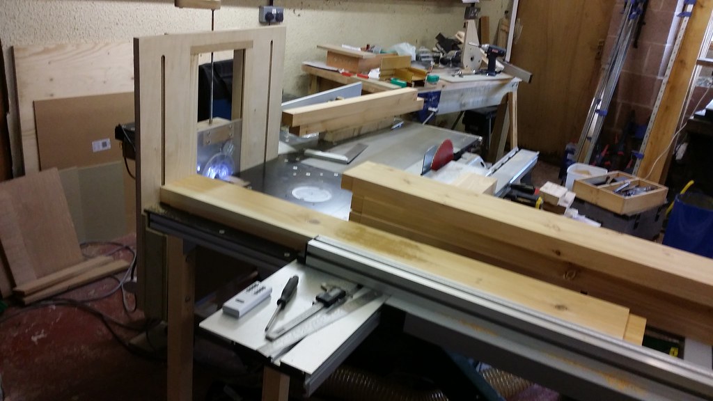
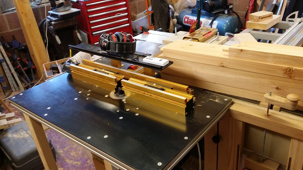
For the tenons on the end of the rails and mullions I used my horizontal router table and a half inch spiral up-cut bit, which is built into the end of my table saw and of my own design. I can adust the height of the perspex plate holding the router by winding a 1mm pitch threaded rod, which gives very precise adjustment of the cutter height (tenon thickness). The horizontal router table is positioned so that I can use the sliding beam of my tablesaw, which makes this job really easy. I have dust extraction from both the router and the table insert, which is very effective. The router is held in place by two toggle clamps so can be fitted or removed in seconds. At some point I intend to make up a proper tenoning sled as the support from the exising cross-cut fence on the saw is not too great.
It took me a while to figure out the length of the tenons and the length of the rails I would need because of all the details around the glazing assembly. I eventually worked it out as follows:
* Starting with the final width of the door (1240mm), subtract twice the width of the stiles (100mm) and add the mortice depth (52mm), I ended up needing the rails to be 1144mm long
* I'm making the doors with an 18mm glazing rebate, therefore the tenons need to be 52mm minus 18mm for the glazing rebate so 34mm
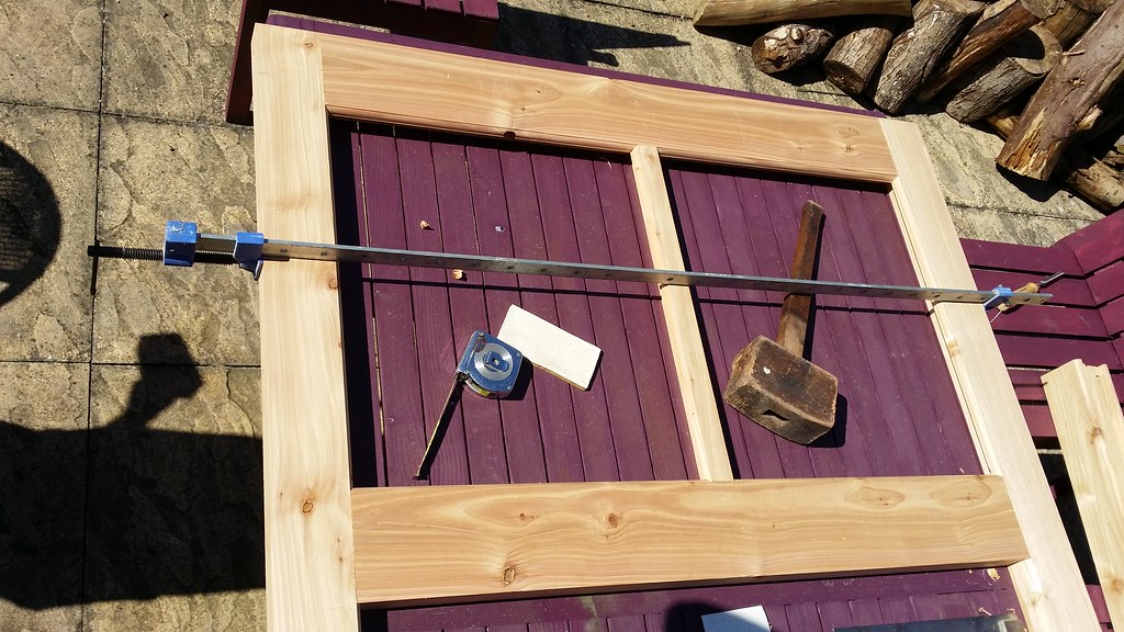
Due to the length of time it took me to square off all the tenons and a long Easter Sunday lunch, this was where I was by the end of day two:
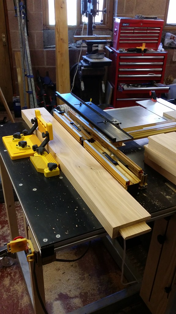
Now the fun really begins with all the coping and profiling cuts. I decided to start with the rebate for the glazing (18mm wide rebate, cutter height set to be flush with the top of the mortices which was about 28.5mm). I cut the rebates on the stiles, rails and mullions in three stages with a 30mm cutter. Having an Incra fence makes all the set-up and staging really easy. As only the top section of the door is glazed, I only machined the glazing rebates part way. Working out the outside faces and orientation of all pieces before you start is really essential here. I find it best if I am really methodical with the way I position the pieces ready for cutting and take my time to not make a cut in the wrong face - I have done this so many times it's not even remotely funny. The second image shows some experimentation with the Magswitch featherboards again, which worked out pretty good. My table saw extension (which is my router table) is made from 6mm blackened steel, no T track to fill with dust is really wonderful!
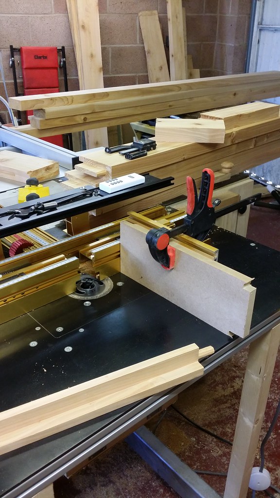
After earlier experimentation, I settled on coping the ends of the rails and mullions before cutting the profiles around the glazing. I'm building the doors so that the glazing bars go on the inside, so all of this work is on what will become the outside bits. The thickness of timber left after the glazing rebates were cut is 15.5mm, but I wanted to leave a quirk on the frame around the glazing. I'm using Wealden's Sash Ovolo cutters (T1360 and T1365), and the round-over profile has a height of 12mm so to leave an even-looking quirk I set the cutter height at 13.7mm. The cutter height needs to be exactly the same on the scribing and profiling cutters for the end result to match. With the scribing cutter, a second pass flush with the cutter height flush with the glazing rebate (15.5mm) is needed so the top of the tenon fits. To get the matching quirk on the stiles, I needed to cut into the shoulder of the already cut tenon by the glazing rebate minus the quirk height - so approx. 16.3mm on each side. This is the set-up I used to cut the scribes, with a piece of sacrificial MDF clamped to the Incra right angle fixture to control blow-out. This worked ok, although the size of pieces are really on the limit of what this setup is capable of and I would opt to use a proper sliding tenoning carriage in the future - something to make for the other side of my saw/router setup.
I then set the cutter height for the profiling cutter. It's bearing guided, but rather than rely on that I decided to use the router fence to creep up a bit on the final setting, and I'm glad I did because somehow scribing the tenons ended up about half a mm out on what I planned, so just jumping straight to the final setting would have left the rails 1mm too short on the scribed side, which would have looked rather pants. The final length is a critical dimension to get right for a good fit.
Testing the fit afterwards - looking good!
The quirk on the profiled stile was removed after machining with a chisel. Likewise I had to remove a small bit of the glazing rebate in the stiles to get the lower rail to fit.
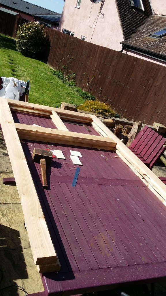
I then cut a rebate in the lower sections of the stiles and the bottom glazing rail, this will accept some tongue and groove panelling. Both doors put together for a test.
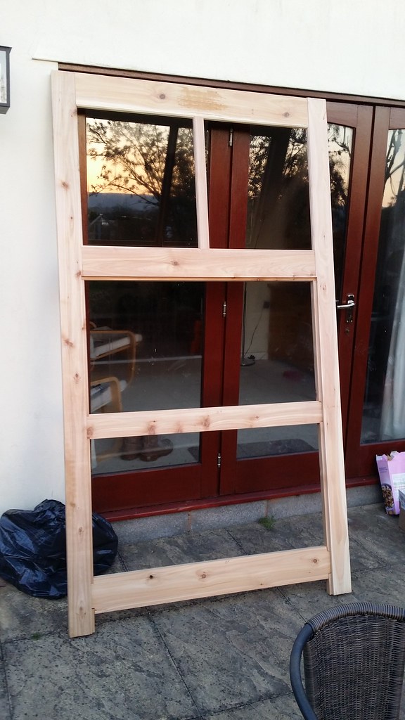
Last job on Monday way to plane up the lower rails and cut half tenons to fit. The thicknessing took ages to get the wood down to the right dimensions, because the thickness is reduced by the tongue and groove panelling that will go on the front. Test assembly at the end of Monday:
All in all considering it's my first attempt at glazing in a door and first proper attempt at scribed tenons I'm happy with how it's turning out. Next up I need to cut some half lap joints in the lower rails for some cross bracing, glue up with Aerolite and then make the tongue and groove boards before sanding and finishing. All the complex stuff is done now, the most head scratchy parts were done in less than a day and it looks like it will turn out ok. The time was probably spent evenly between the stock prep, mortice and tenons and the profiling/scribing. After three days running machines in my workshop over a bank holiday, I'm not sure my neighbours share my enthusiasm for woodworking though.
Started out on Saturday morning with a big pile of rough sawn cedar that's been drying in the garage since last summer. Usual ripping and planing operations to get down to the right size of timber. I recently bought some new magswitch accessories which I found useful when planing to help control the longer pieces which are a little over 2m in length - the downward pressure on the outfeed table was particularly useful for surface planing, and it was also much easier squaring the edge off of wider pieces with the featherboards set to push against the fence.
After the first day's work, a nice load of square and straight timber ready for making into the frames.
Next up was morticing the stiles and also the rails for the mullions. I built a mortice jig for routing these with - it was inspired by the Trend mortice and tenon jig mainly. There is a perspex plate on the top that supports the router with two sliding dovetail guides made of UHMW plastic, this keeps the plate attached and perpendicular to the body of the jig. There is a 30mm slot routed into the perspex plate for a guide bush to ride left-right in, and adjustable end stops. I made a small gauge from an offcut of the perspex to enable me to line everything up. A 1/2" spiral up-cut bit made really clean mortices.
All mortices cut ready for squaring off with a chisel (which I am terrible at).
For the tenons on the end of the rails and mullions I used my horizontal router table and a half inch spiral up-cut bit, which is built into the end of my table saw and of my own design. I can adust the height of the perspex plate holding the router by winding a 1mm pitch threaded rod, which gives very precise adjustment of the cutter height (tenon thickness). The horizontal router table is positioned so that I can use the sliding beam of my tablesaw, which makes this job really easy. I have dust extraction from both the router and the table insert, which is very effective. The router is held in place by two toggle clamps so can be fitted or removed in seconds. At some point I intend to make up a proper tenoning sled as the support from the exising cross-cut fence on the saw is not too great.
It took me a while to figure out the length of the tenons and the length of the rails I would need because of all the details around the glazing assembly. I eventually worked it out as follows:
* Starting with the final width of the door (1240mm), subtract twice the width of the stiles (100mm) and add the mortice depth (52mm), I ended up needing the rails to be 1144mm long
* I'm making the doors with an 18mm glazing rebate, therefore the tenons need to be 52mm minus 18mm for the glazing rebate so 34mm
Due to the length of time it took me to square off all the tenons and a long Easter Sunday lunch, this was where I was by the end of day two:
Now the fun really begins with all the coping and profiling cuts. I decided to start with the rebate for the glazing (18mm wide rebate, cutter height set to be flush with the top of the mortices which was about 28.5mm). I cut the rebates on the stiles, rails and mullions in three stages with a 30mm cutter. Having an Incra fence makes all the set-up and staging really easy. As only the top section of the door is glazed, I only machined the glazing rebates part way. Working out the outside faces and orientation of all pieces before you start is really essential here. I find it best if I am really methodical with the way I position the pieces ready for cutting and take my time to not make a cut in the wrong face - I have done this so many times it's not even remotely funny. The second image shows some experimentation with the Magswitch featherboards again, which worked out pretty good. My table saw extension (which is my router table) is made from 6mm blackened steel, no T track to fill with dust is really wonderful!
After earlier experimentation, I settled on coping the ends of the rails and mullions before cutting the profiles around the glazing. I'm building the doors so that the glazing bars go on the inside, so all of this work is on what will become the outside bits. The thickness of timber left after the glazing rebates were cut is 15.5mm, but I wanted to leave a quirk on the frame around the glazing. I'm using Wealden's Sash Ovolo cutters (T1360 and T1365), and the round-over profile has a height of 12mm so to leave an even-looking quirk I set the cutter height at 13.7mm. The cutter height needs to be exactly the same on the scribing and profiling cutters for the end result to match. With the scribing cutter, a second pass flush with the cutter height flush with the glazing rebate (15.5mm) is needed so the top of the tenon fits. To get the matching quirk on the stiles, I needed to cut into the shoulder of the already cut tenon by the glazing rebate minus the quirk height - so approx. 16.3mm on each side. This is the set-up I used to cut the scribes, with a piece of sacrificial MDF clamped to the Incra right angle fixture to control blow-out. This worked ok, although the size of pieces are really on the limit of what this setup is capable of and I would opt to use a proper sliding tenoning carriage in the future - something to make for the other side of my saw/router setup.
I then set the cutter height for the profiling cutter. It's bearing guided, but rather than rely on that I decided to use the router fence to creep up a bit on the final setting, and I'm glad I did because somehow scribing the tenons ended up about half a mm out on what I planned, so just jumping straight to the final setting would have left the rails 1mm too short on the scribed side, which would have looked rather pants. The final length is a critical dimension to get right for a good fit.
Testing the fit afterwards - looking good!
The quirk on the profiled stile was removed after machining with a chisel. Likewise I had to remove a small bit of the glazing rebate in the stiles to get the lower rail to fit.
I then cut a rebate in the lower sections of the stiles and the bottom glazing rail, this will accept some tongue and groove panelling. Both doors put together for a test.
Last job on Monday way to plane up the lower rails and cut half tenons to fit. The thicknessing took ages to get the wood down to the right dimensions, because the thickness is reduced by the tongue and groove panelling that will go on the front. Test assembly at the end of Monday:
All in all considering it's my first attempt at glazing in a door and first proper attempt at scribed tenons I'm happy with how it's turning out. Next up I need to cut some half lap joints in the lower rails for some cross bracing, glue up with Aerolite and then make the tongue and groove boards before sanding and finishing. All the complex stuff is done now, the most head scratchy parts were done in less than a day and it looks like it will turn out ok. The time was probably spent evenly between the stock prep, mortice and tenons and the profiling/scribing. After three days running machines in my workshop over a bank holiday, I'm not sure my neighbours share my enthusiasm for woodworking though.


") ) formic acid and phosphoric acid. Or maybe the other way around. They seemed to be interchangeable in use.
) formic acid and phosphoric acid. Or maybe the other way around. They seemed to be interchangeable in use.