misterfish
Established Member
I've done a quick analysis of my machine and there are some obvious differences.
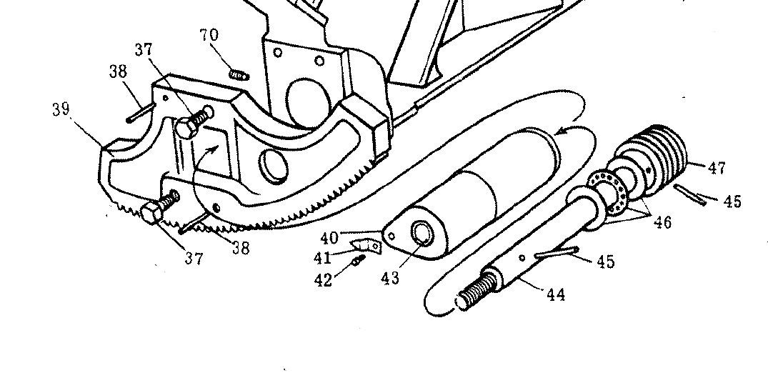
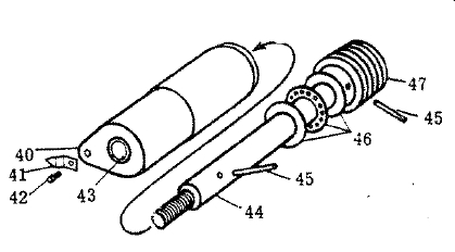
First the details of the parts
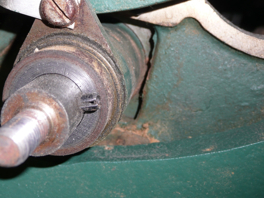
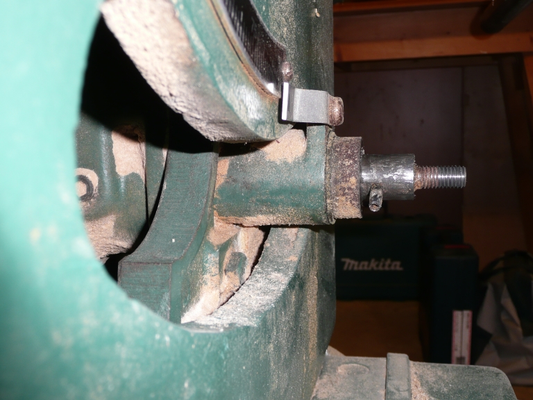
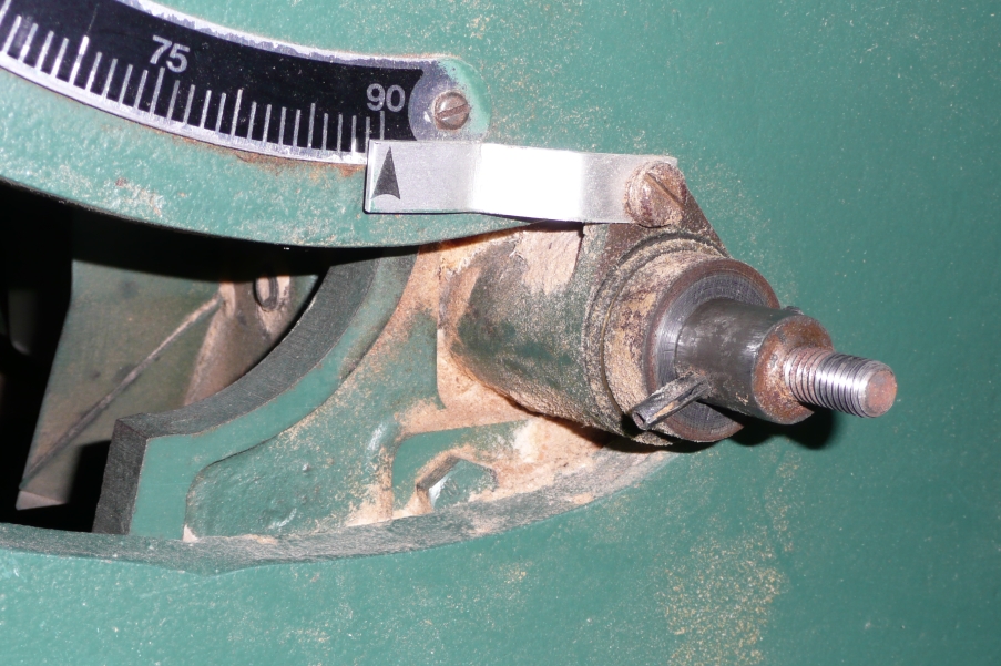
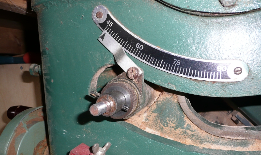
Now the external appearance of the mechanism - on my machine the whole shaft assembly is further in the machine and the actual angle pointer is a different shape and closer in to the body of the saw.
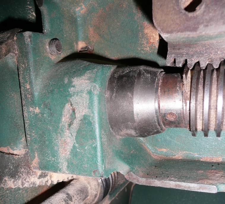
As for the inner bits I have an inner partially coned (to miss the trunnion teeth) spacer, then the thrust washers and finally the the worm gear held right beneath the teeth on the trunnion.
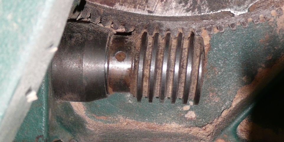
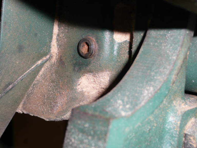
My immediate thoughts are that maybe part 40 is fixed too far forwards. Maybe the whole assembly has been disassembeled in the past and not put back together correctly. In fact looking at the pictures it looks as if there is a repaired part of the trunnion casting just below the worm gear. It is quite possible that if and when it was put back together incorrectly that the end of the worm gear reached far enough to just mesh with the teeth on the trunnion - after use the end of the worm gear has worn and no longer meshes.
With the handle components removed and the front roll pin(s) also removed the whole shaft ought to be in a position to move inwards and allow access to the roll pin holding the worm gear to the shaft.
I'll go back and get my head and camera right inside the saw and see if I can get any more details or info including how part 40 fixes to the trunnion mechanism.
Misterfish
First the details of the parts
Now the external appearance of the mechanism - on my machine the whole shaft assembly is further in the machine and the actual angle pointer is a different shape and closer in to the body of the saw.
As for the inner bits I have an inner partially coned (to miss the trunnion teeth) spacer, then the thrust washers and finally the the worm gear held right beneath the teeth on the trunnion.
My immediate thoughts are that maybe part 40 is fixed too far forwards. Maybe the whole assembly has been disassembeled in the past and not put back together correctly. In fact looking at the pictures it looks as if there is a repaired part of the trunnion casting just below the worm gear. It is quite possible that if and when it was put back together incorrectly that the end of the worm gear reached far enough to just mesh with the teeth on the trunnion - after use the end of the worm gear has worn and no longer meshes.
With the handle components removed and the front roll pin(s) also removed the whole shaft ought to be in a position to move inwards and allow access to the roll pin holding the worm gear to the shaft.
I'll go back and get my head and camera right inside the saw and see if I can get any more details or info including how part 40 fixes to the trunnion mechanism.
Misterfish