Whilst not really woodwork, most of us do work that is aimed at improving our homes, and I thought that my venture into under floor heating may be of interest. This is NOT a definitive “how to” thread. I am not a plumber, but never-the-less the end result is one that I am pleased with.
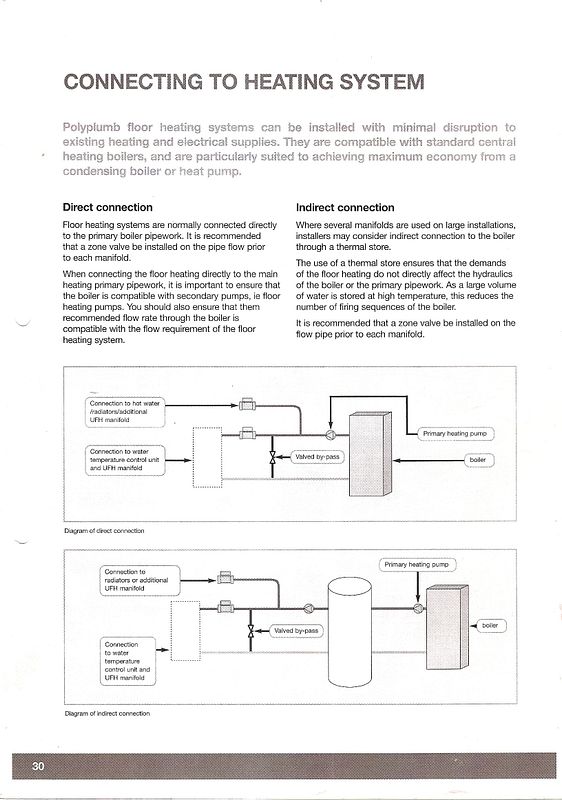
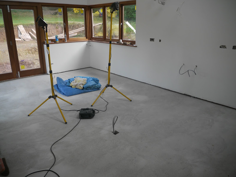
The building work on my kitchen extension is more or less complete, so time to think about heating. We have decided on an underfloor heating wet system using our existing oil fired condensing boiler. The current system is divided into 3 separately controlled zones - downstairs, upstairs and hot water. The intention is to make the kitchen/living room extension a 4th separate zone as the levels of insulation are exceptionally high and we more or less expect to live out there in the winter, and the summer too with the bifold doors open.
Having just been charged £180 to re-route 2 pipes which had been clipped to the wall that has just been demolished, and which were intended to go under the floor, and then find after the plumber had gone that they were still going to exit the wall above floor level, I didn’t even bother to get a quote. Time to DIY.
After lots of reading around I decided to go for the Polypipe system, using their single room zone valve, and a wireless programmable thermostat.
First job is to insulate the floor with 100mm of Celotex. This is simply laid on the floor slab and the joints taped over to stop it moving about before the screed is laid.
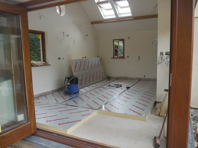
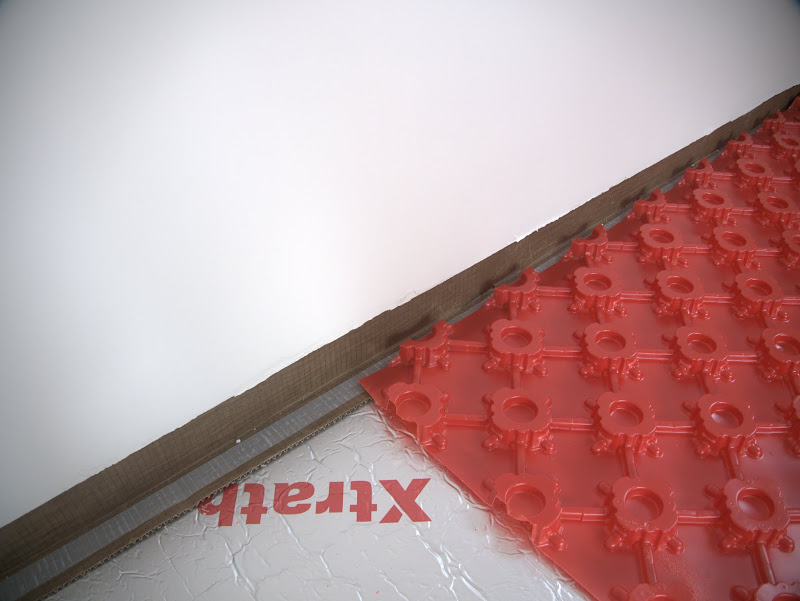
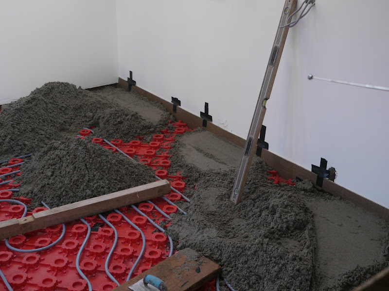
The walls are also insulated with 65mm of Celotex in the cavity, and a further 30mm behind dot’n dab Thermal Check K plasterboard. The floor screed will need room for thermal expansion and contraction, so a thin strip of Celotex 25mm thick is used to isolate the screed from the wall thermally. This is just a friction fit between the Thermal check plasterboard and the under floor Celotex. The loose cable on the floor will provide power to the island.
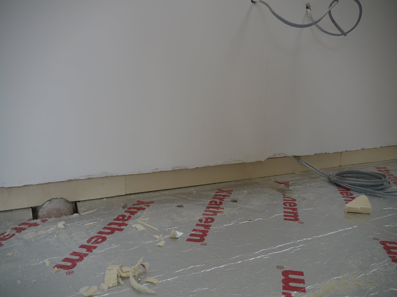
With a 25mm strip of Celotex all round, a final layer of proprietary Polypipe expansion material is attached to the top of the underfloor Celotex with double sided tape and this bends through 90 degrees up the wall, and in front of door frames etc. It’s also important to use this where the new screed meets the old screed in the existing building so that the new screed is completely isolated to allow for expansion on all sides.
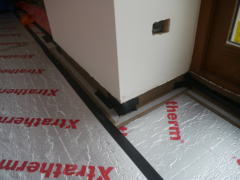
A rigid plastic barrier is laid over the Celotex, which is castellated a bit like a giant egg box, and the 15mm underfloor pipe will be held in place by the castellations. This is attached around the edges by the double sided tape on the expansion strip.
The cable for the island is contained within a conduit and is embedded in the Celatex under the rigid castellated sheet.
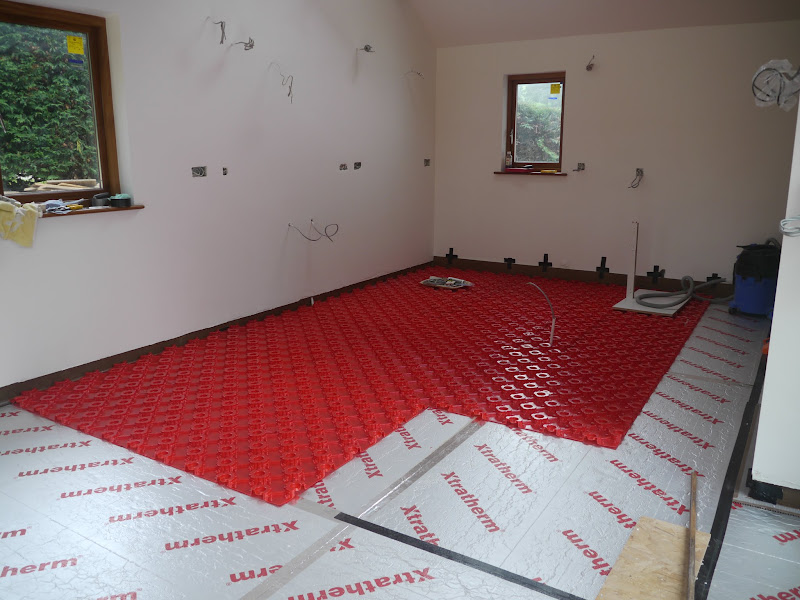
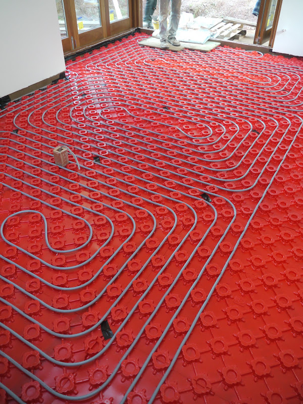
The pipe comes in 100m rolls and we’ll be laying 240m of it, so we need 3 rolls. As there must be no joins within the floor screed, this means that all joins must be above floor level, which means laying 3 circuits and then joining them via a simple manifold once they are above the floor, and ideally near the boiler. Here’s the first circuit laid.
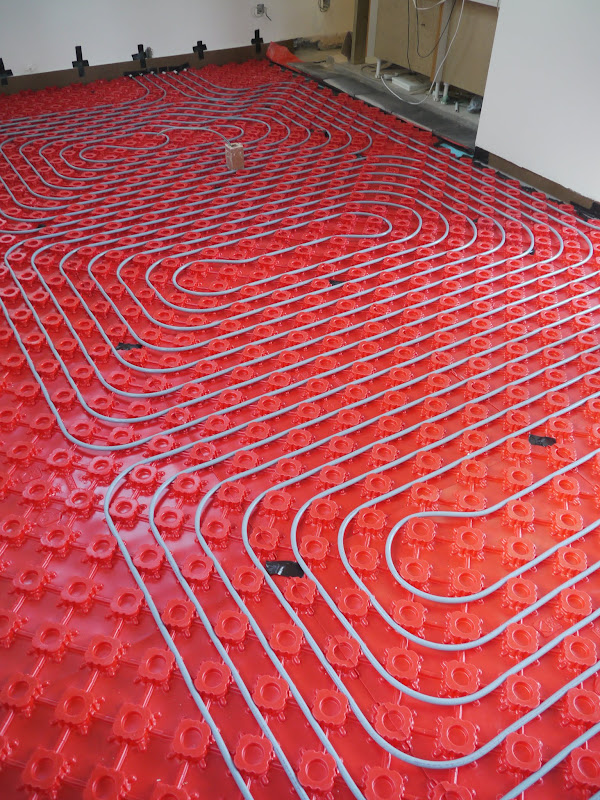
..... and the second.
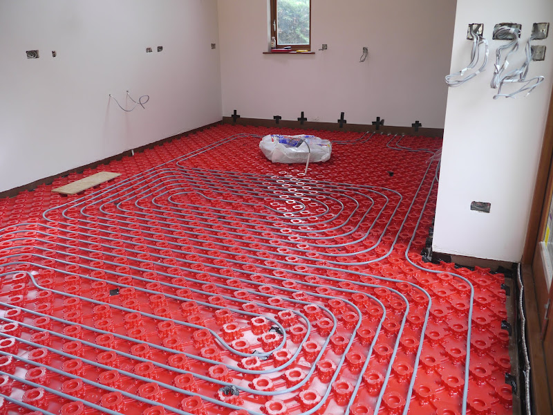
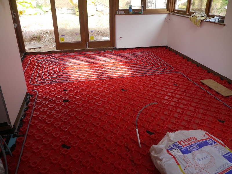
.... and the third. I’ve put a removable wooden plug around the island cable so that there is an appropriately sized square hole to take a box for a floor socket. I don’t want to have to drill anywhere near the pipes! The 3 separate circuits exit the kitchen through conduits in the far wall. The 600mm space down the side and far end will be covered by kitchen units so i did’t want to heat the floor beneath them. The pipes exit the kitchen through the far wall in the 2nd photo .....
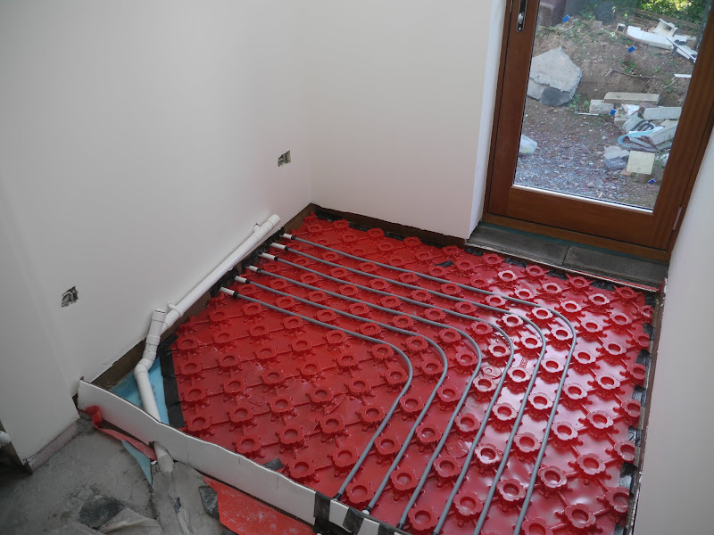
... come out in the utility room ...
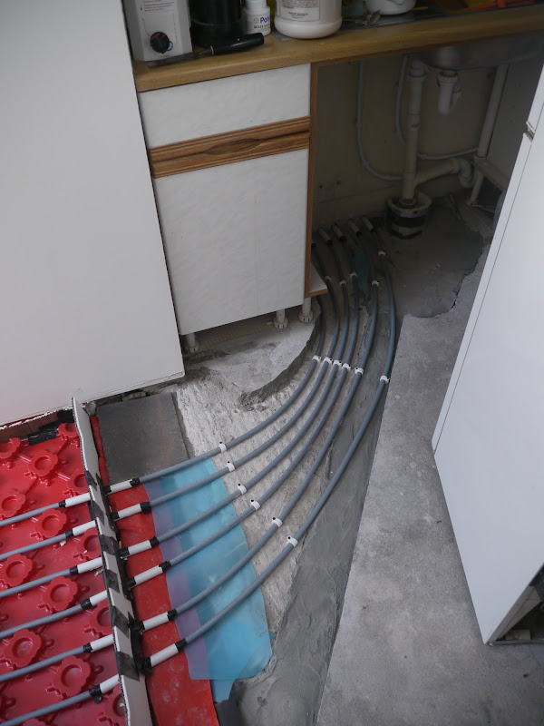
.. exiting the utility room under the sink. You can see the thermal expansion material crossing the floor between the old floor and the new area to be screeded, ensuring that the heating pipe is protected by conduit as it passes from one to the other. Having exited the utility room under the sink ...
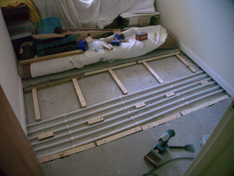
..... the pipes cross the floor of the study in conduits. Why have I lifted twice the width of old screed on the study floor as I appear to need? Well, a clear run 600mm wide was needed, and the cynical may say that having measured where the side of the excavation had to be the night before, I then excavated 600mm on the wrong side of the line. I couldn’t possibly comment! Anyway - here it is with battens screwed to the floor slab ready to be covered with 18mm floor grade chipboard. I decided against laying a concrete screed as it would take weeks to dry sufficiently to relay the carpet and I wanted it back down asap.
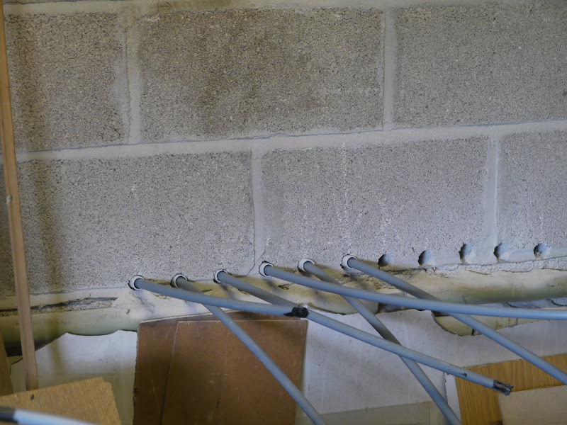
.... and finally the pipes exit the wall in the garage just above the dpc, again protected in conduit. There on the right are the carefully drilled holes for the pipes in the wrong position! No harm done. They can easily be filled in. You’ll notice that I’ve taped over the ends of all pipes to ensure that no grit gets inside them whilst they are snaking about during laying. That would be the kiss of death to the pump.
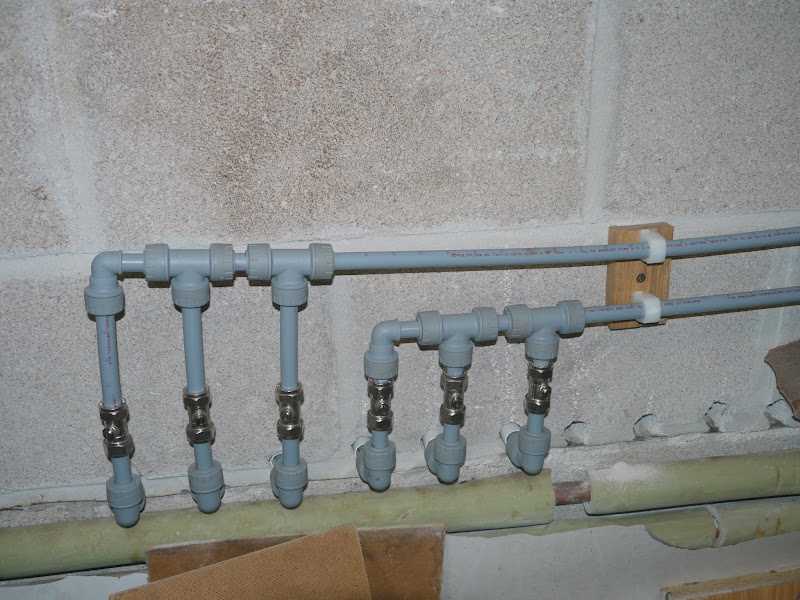
Next job is to join the 3 flows and 3 returns into a single flow and return by constructing a simple manifold for each using elbows, spigots and T’s. Whilst not strictly necessary, I’ve put an inline stop in each circuit so that in the event of future problems I can isolate each part of the circuit independently and it will also help to balance the flow between the 3 circuits in the event that they are not even.
Next job was to check for leaks before the screed gets laid over the top and its embedded in concrete forever. No photos of that but I simply connected a domestic hose to the flow and a spare inline stop to the return and filled each circuit in turn. Once the flow from the hose was steady I closed the inline stop in the return whilst leaving the hose switched on and checked for leaks along the entire length of the pipework. As there are no joins other than those you see in the photo of the manifolds I wasn’t expecting any, but just wanted to ensure there were no manufacturing errors.
Time to lay the screed and cover up all that work for ever.
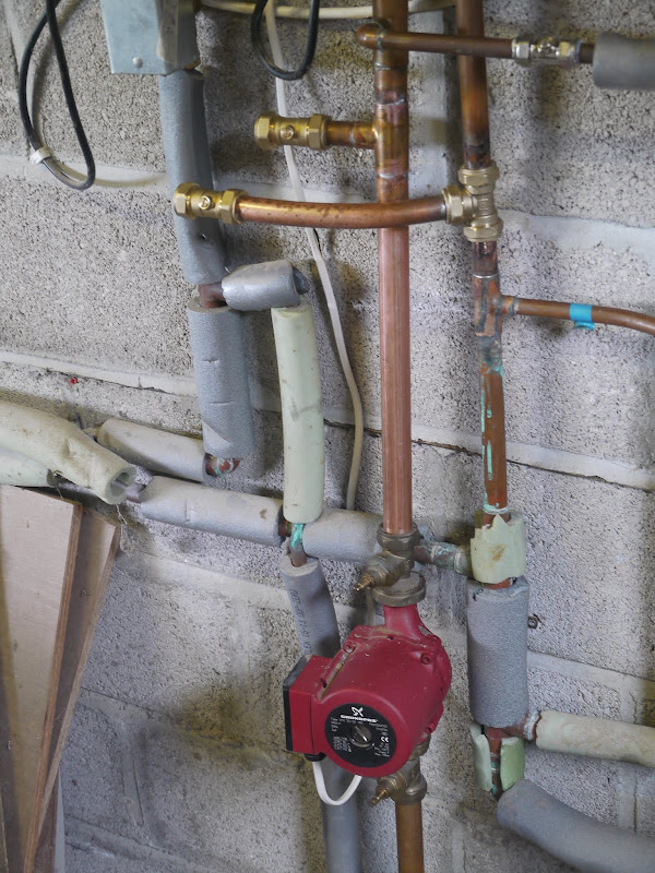
Now to connect the various components to the existing system. The system was drained and a 22mm T was connected to the boiler flow and return. The UFH relies on the existing CH pump so the connection to the flow MUST be made after the pump and NOT before. This involved moving the pump slightly to make room, whilst ensuring that the pump was not at the lowest part of the system where it may be pumping sludge. The two T’s are clearly shown in this photo. I wanted to use soldered joints for each, but an annoying steady drip down the return pipe made a good joint impossible to achieve so in the end I gave up and used a compression fitting. Again i have put in a pair of inline stops so that the entire UFH system can be isolated, and it also enabled me to refill and commission the existing system as soon as the T connections had been made.
Next job is to fit the UFH zone valve, mixer/pump unit, and connect to the underfloor pipework. A quick explanation of principles may be helpful here.
The UFH system is controlled from a programmable thermostat. When the stat calls for heat, and the inbuilt timer says that heat is required at this time, the zone valve opens and the boiler and existing CH pump fire up. The CH pump sends water through the flow from the boiler to the mixer valve and back down the return to the boiler. When the flow through the mixer valve reaches 45 degrees, the UFH pump starts and pumps water through the UFH flow and UFH return.
Whilst the temperature of the water in a radiator system may be around 65 degrees, the temperature for the under floor water must be between 45 and 50 degrees or else your floors will get too hot. The temperature for the underfloor water is set with the red knob on top of the mixer unit, and when it reaches 50 degrees it starts to mix cool water from the UFH return to the UFH flow so that the flow is restricted to 50 degrees even though the water from the boiler may be at 65 degrees. Once the return water is up to 50 degrees the boiler shuts down but if the thermostat is still calling for heat the pumps keep circulating the water until it has cooled and the boiler cuts in again.
A photo of the installation should make this clear.
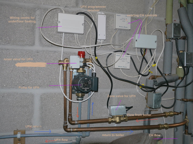
The existing CH wiring is nothing to do with me! However, with a combination of reading instructions and looking at the existing wiring the UFH connections were not difficult to make and it all worked first time. Just need to clip back the cables and put some insulation around the pipes and the jobs done. However it is still only 4 weeks since the screed was laid and it needs another 2 weeks minimum before the UFH is used regularly as forcing the drying with heat will weaken the screed.
Overall costs were about £1100 for all the UFH pipework and controls. I’m not sure how much I’ve saved - but it cannot be less than £1,000. Just as importantly I now have a system that I completely understand in the event of any future problems. Hope this is helpful to someone. It wasn’t difficult so give it a go!
The building work on my kitchen extension is more or less complete, so time to think about heating. We have decided on an underfloor heating wet system using our existing oil fired condensing boiler. The current system is divided into 3 separately controlled zones - downstairs, upstairs and hot water. The intention is to make the kitchen/living room extension a 4th separate zone as the levels of insulation are exceptionally high and we more or less expect to live out there in the winter, and the summer too with the bifold doors open.
Having just been charged £180 to re-route 2 pipes which had been clipped to the wall that has just been demolished, and which were intended to go under the floor, and then find after the plumber had gone that they were still going to exit the wall above floor level, I didn’t even bother to get a quote. Time to DIY.
After lots of reading around I decided to go for the Polypipe system, using their single room zone valve, and a wireless programmable thermostat.
First job is to insulate the floor with 100mm of Celotex. This is simply laid on the floor slab and the joints taped over to stop it moving about before the screed is laid.
The walls are also insulated with 65mm of Celotex in the cavity, and a further 30mm behind dot’n dab Thermal Check K plasterboard. The floor screed will need room for thermal expansion and contraction, so a thin strip of Celotex 25mm thick is used to isolate the screed from the wall thermally. This is just a friction fit between the Thermal check plasterboard and the under floor Celotex. The loose cable on the floor will provide power to the island.
With a 25mm strip of Celotex all round, a final layer of proprietary Polypipe expansion material is attached to the top of the underfloor Celotex with double sided tape and this bends through 90 degrees up the wall, and in front of door frames etc. It’s also important to use this where the new screed meets the old screed in the existing building so that the new screed is completely isolated to allow for expansion on all sides.
A rigid plastic barrier is laid over the Celotex, which is castellated a bit like a giant egg box, and the 15mm underfloor pipe will be held in place by the castellations. This is attached around the edges by the double sided tape on the expansion strip.
The cable for the island is contained within a conduit and is embedded in the Celatex under the rigid castellated sheet.
The pipe comes in 100m rolls and we’ll be laying 240m of it, so we need 3 rolls. As there must be no joins within the floor screed, this means that all joins must be above floor level, which means laying 3 circuits and then joining them via a simple manifold once they are above the floor, and ideally near the boiler. Here’s the first circuit laid.
..... and the second.
.... and the third. I’ve put a removable wooden plug around the island cable so that there is an appropriately sized square hole to take a box for a floor socket. I don’t want to have to drill anywhere near the pipes! The 3 separate circuits exit the kitchen through conduits in the far wall. The 600mm space down the side and far end will be covered by kitchen units so i did’t want to heat the floor beneath them. The pipes exit the kitchen through the far wall in the 2nd photo .....
... come out in the utility room ...
.. exiting the utility room under the sink. You can see the thermal expansion material crossing the floor between the old floor and the new area to be screeded, ensuring that the heating pipe is protected by conduit as it passes from one to the other. Having exited the utility room under the sink ...
..... the pipes cross the floor of the study in conduits. Why have I lifted twice the width of old screed on the study floor as I appear to need? Well, a clear run 600mm wide was needed, and the cynical may say that having measured where the side of the excavation had to be the night before, I then excavated 600mm on the wrong side of the line. I couldn’t possibly comment! Anyway - here it is with battens screwed to the floor slab ready to be covered with 18mm floor grade chipboard. I decided against laying a concrete screed as it would take weeks to dry sufficiently to relay the carpet and I wanted it back down asap.
.... and finally the pipes exit the wall in the garage just above the dpc, again protected in conduit. There on the right are the carefully drilled holes for the pipes in the wrong position! No harm done. They can easily be filled in. You’ll notice that I’ve taped over the ends of all pipes to ensure that no grit gets inside them whilst they are snaking about during laying. That would be the kiss of death to the pump.
Next job is to join the 3 flows and 3 returns into a single flow and return by constructing a simple manifold for each using elbows, spigots and T’s. Whilst not strictly necessary, I’ve put an inline stop in each circuit so that in the event of future problems I can isolate each part of the circuit independently and it will also help to balance the flow between the 3 circuits in the event that they are not even.
Next job was to check for leaks before the screed gets laid over the top and its embedded in concrete forever. No photos of that but I simply connected a domestic hose to the flow and a spare inline stop to the return and filled each circuit in turn. Once the flow from the hose was steady I closed the inline stop in the return whilst leaving the hose switched on and checked for leaks along the entire length of the pipework. As there are no joins other than those you see in the photo of the manifolds I wasn’t expecting any, but just wanted to ensure there were no manufacturing errors.
Time to lay the screed and cover up all that work for ever.
Now to connect the various components to the existing system. The system was drained and a 22mm T was connected to the boiler flow and return. The UFH relies on the existing CH pump so the connection to the flow MUST be made after the pump and NOT before. This involved moving the pump slightly to make room, whilst ensuring that the pump was not at the lowest part of the system where it may be pumping sludge. The two T’s are clearly shown in this photo. I wanted to use soldered joints for each, but an annoying steady drip down the return pipe made a good joint impossible to achieve so in the end I gave up and used a compression fitting. Again i have put in a pair of inline stops so that the entire UFH system can be isolated, and it also enabled me to refill and commission the existing system as soon as the T connections had been made.
Next job is to fit the UFH zone valve, mixer/pump unit, and connect to the underfloor pipework. A quick explanation of principles may be helpful here.
The UFH system is controlled from a programmable thermostat. When the stat calls for heat, and the inbuilt timer says that heat is required at this time, the zone valve opens and the boiler and existing CH pump fire up. The CH pump sends water through the flow from the boiler to the mixer valve and back down the return to the boiler. When the flow through the mixer valve reaches 45 degrees, the UFH pump starts and pumps water through the UFH flow and UFH return.
Whilst the temperature of the water in a radiator system may be around 65 degrees, the temperature for the under floor water must be between 45 and 50 degrees or else your floors will get too hot. The temperature for the underfloor water is set with the red knob on top of the mixer unit, and when it reaches 50 degrees it starts to mix cool water from the UFH return to the UFH flow so that the flow is restricted to 50 degrees even though the water from the boiler may be at 65 degrees. Once the return water is up to 50 degrees the boiler shuts down but if the thermostat is still calling for heat the pumps keep circulating the water until it has cooled and the boiler cuts in again.
A photo of the installation should make this clear.
The existing CH wiring is nothing to do with me! However, with a combination of reading instructions and looking at the existing wiring the UFH connections were not difficult to make and it all worked first time. Just need to clip back the cables and put some insulation around the pipes and the jobs done. However it is still only 4 weeks since the screed was laid and it needs another 2 weeks minimum before the UFH is used regularly as forcing the drying with heat will weaken the screed.
Overall costs were about £1100 for all the UFH pipework and controls. I’m not sure how much I’ve saved - but it cannot be less than £1,000. Just as importantly I now have a system that I completely understand in the event of any future problems. Hope this is helpful to someone. It wasn’t difficult so give it a go!