The Adventures of Jim's plane's Smaller Brother

UKworkshop.co.uk

Help Support UKworkshop.co.uk:

This site may earn a commission from merchant affiliate links, including eBay, Amazon, and others.

Richard T

Established Member
Joined
24 Apr 2009
Messages
1,743
Reaction score
1
Location
Wet Midlands
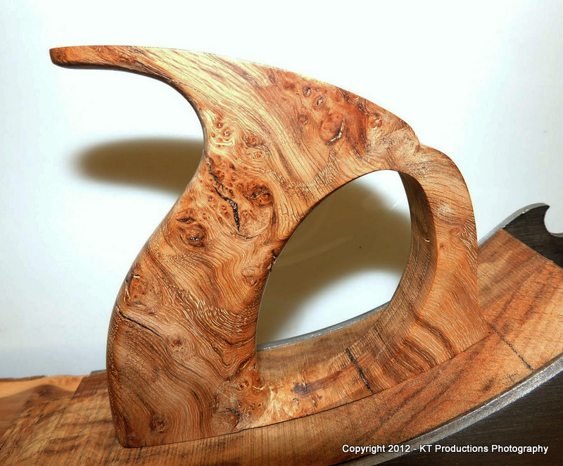
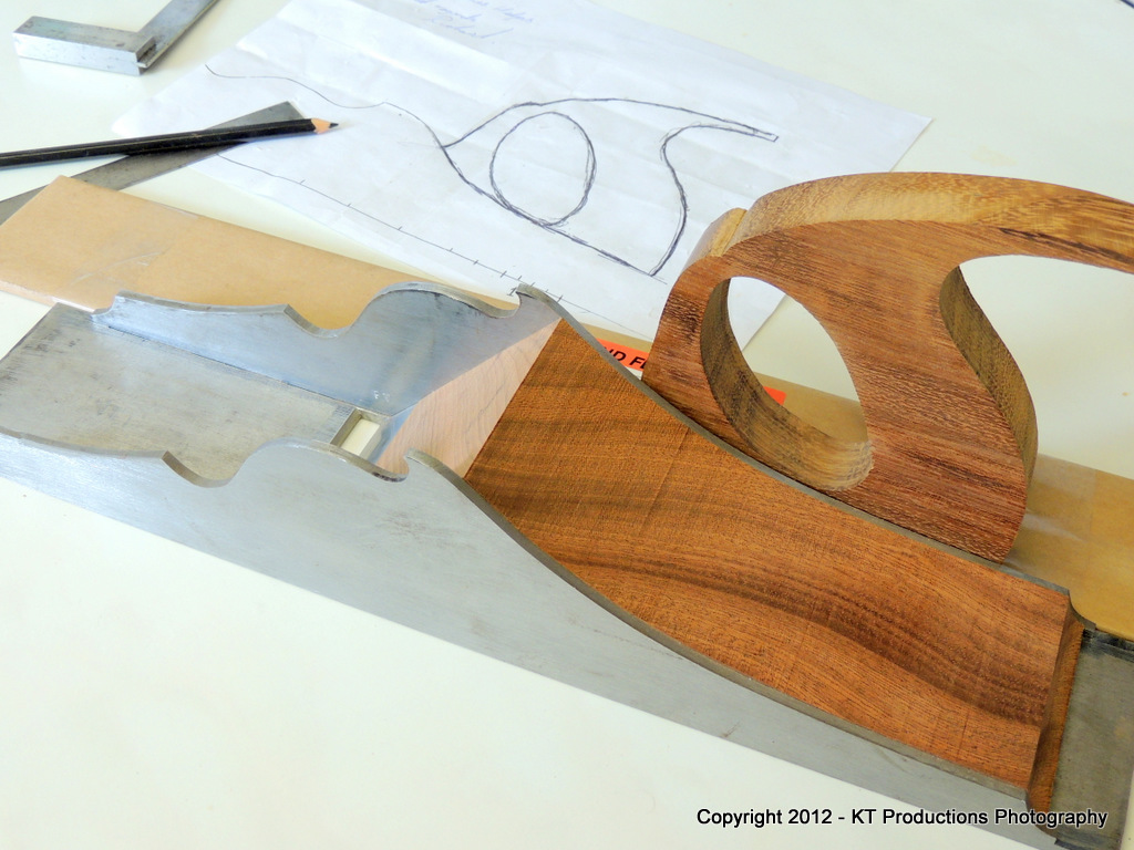
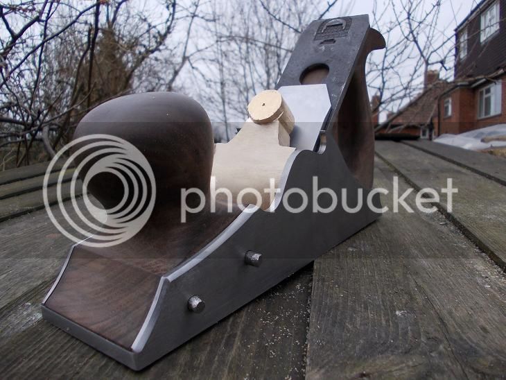
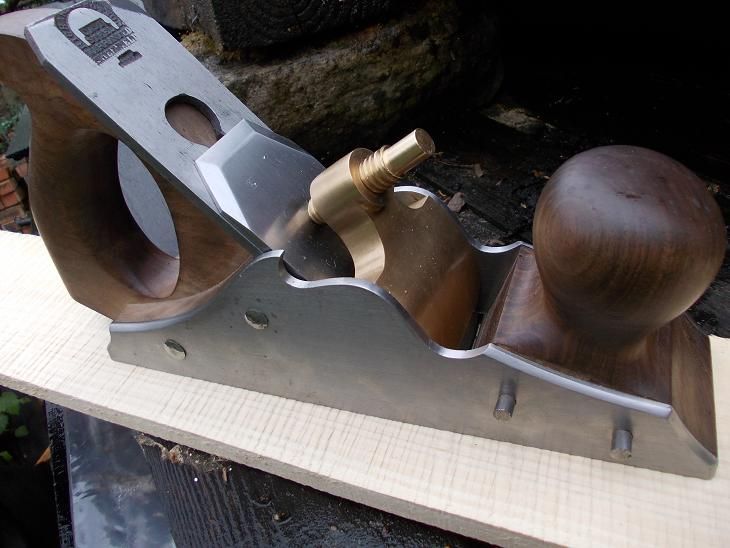
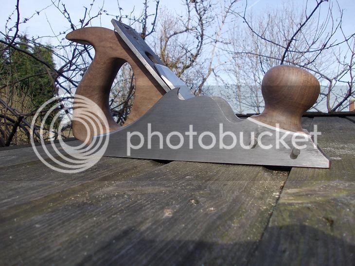
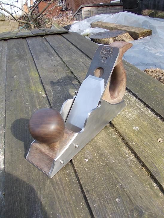
When I made Jimi his panel plane shell and exaggerated the top of the cupid bow (Japanese wave style) I did so because I had already cut out the sides for this smoother in that way and couldn't bare to return to the accepted 'norm'.
DSCN0995s_zpsffb313df.jpg


It is 9 - 1/2" long (sole) and made to take a 2" iron, though it's a bit narrow for much lateral movement. 50 degree pitch.
DSCN0993s_zpsf54163a0.jpg


The sides are 3mm and the sole is 6mm. It has the same size frog block as does Jim's 15 - 1/2 incher so it seems even more big and solid in this little plane.

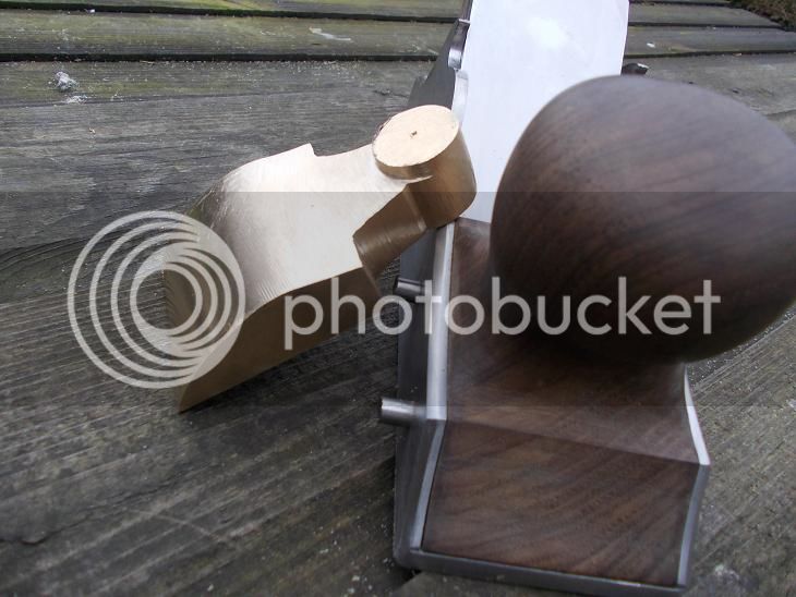
I made a cap iron after the style (loosely) of Karl H. 3mm mild steel bend cold over the curved area of the side of the anvil. I don't think I will bother with trying to build up the female thread with brass - 3mm should be plenty thick enough.
DSCN0997s_zps56bb8f67.jpg


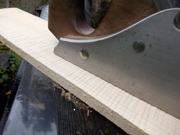
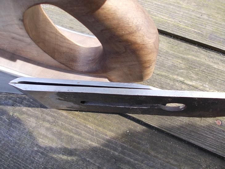
The iron is the only true parallel I have yet found although it develops a bit of extra thickness toward the end. This I will file down instead of opening the mouth that last smidgeon.
DSCN0999s_zpsfbfd960c.jpg


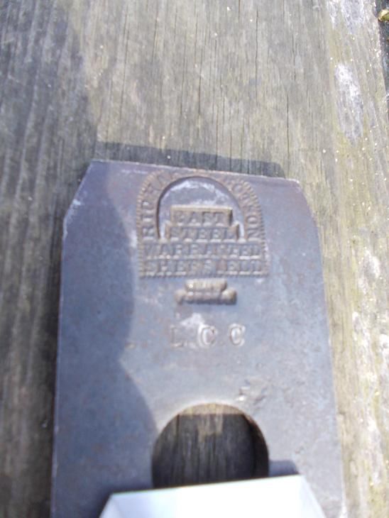
It's by Richard Ibbotson and appears to have had its top clipped and have "L C C" stamped cold underneath the hot stamped maker's mark. Any thoughts on either of these things?
 
Hi, Richard

That's nice! looks a little dangerous that crest of the wave, need the red flags flying!

Walnut infill?

Pete
 
Thanks Pete,

I know it looks a bit murderous but the lever screw will be high enough to avoid knuckle mismanagement. I think I might have been playing Skyrim a tad too much - looks quite Nordic.

Yup, Walnut from MacTimbers. Still not decide on finish.
 
Not sure I would like to use it day in day out. The crest looks elegant but function has to take precedence IMO.
 
Coming along nicely!

I agree the wave crests look lovely but are maybe a touch dangerous. Can you show us a photo with your hands in place - do any fingers get near to the points?
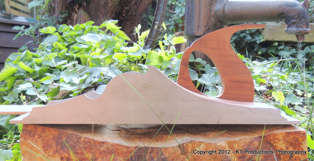
Presumably you have a bit more chamfering to do, which could make them look extremely smart.

As for the iron, as it's been clipped already (presumably by the London County Council who didn't want it pinched from a school workshop) how about rounding the corners off a bit more, 18th century style? (It's just a pity the stamp isn't lower.)

What have you got planned for the lever cap?
 
I wouldn't be surprised if the iron wasn't clipped like that just so it would fit on a shelf. They did things like that in schools.

Nice looking plane by the way, well done. I admire your skill

Mick
 
:) They are well out of the way - I'll try to get a photo of the gripitude. (They're not very sharp TBH)

The shanfer .... I thought I'd finished. :oops: I always do too little of it I think - I see Richard A's Norris every so often and am re - surprised every time by the depth of it.

Thanks for the info Andy."CC" is very often County Council (when it's not "CheshireChappie") The Iron was one in a selection from an auction. Very mixed lot of sizes, conditions and ages. Could very well have been pinched from school.

I am lever capping at present, taking advantage of this balmy weather and peeping out of hibernation. I'll get some more photos of progress.

Thanks Mick

There's an awful lot of swearing that goes into it though ....
 
Richard - it's hard to judge the chamfering in the photos - far easier to take more off than it would be to put it back!
If I were making this plane I'd want to see the lever cap in place before I could say I had finished the sides and spend hours admiring it from all angles before picking up a file. Actually, scrub that, if I were making this plane it would still be a doodle on the back of an envelope and years away from completion!

Also, all the rivets would look like the front ones.

Permanently! ;-)
 
That looks to be well on the way to being a very fine plane. Are you going for a screw adjuster, or tap-tap adjustment?

I think Andy's right about the chamfering - get the lever cap in place, and see what it looks like then. As Mignal said - function first, and form will follow.

The 'L.C.C.' mark is almost certainly not Lancashire County Council - they wouldn't have allowed in anything made in Yorkshire!
 
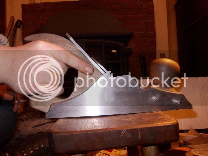
Finger well short of spiky cupid bow.

DSCN1007s_zps931ac090.jpg


Funny you should mention the rivets Andy, when I put those in last year I drilled through one side, through the wood and spotted the inside of the other side to mark/centre it. Then thinking that it would be a good idea to take out the infill to drill through the other side to keep swarf from embedding in the wood I did so ....which was a bad idea. The drill must have moved quite a bit and I had to taper the ends of the rivets to get them through with the infill back in.
When I drill for the back rivets I will definitely go through the lot in one go. There's no reason for them to be dead square or parallel and they will be unseen (I hope) when finished.

What really does matter however, is the pivot for the lever cap. Not only do the holes in the sides need to be absolutely right but drilling in a straight line through the cap itself seems to be an impossible ask. My drill press is square and solid but solid enough ? The most accurate I could get it would be to drill it with the lathe but I just don't believe it will work looking at the task from this side of doing it.
I will try it first on an off cut off a similar width.
 
Thanks CC,

I have left room for an adjuster on this one but will put the rest together first having practised screw cutting and bolt heading, knurling etc. with the cap and lever cap screws.

In fact I did think of buying an adjuster from those awfully nice Iles people to see how they put them together. I have the Veritas version but it is a bit short and weedy for for a comparison.
 
Hi Richard, :D
I like much this plane. =D> I am sure it will be a fine smoother!
I like the knob projecting forward, It looks great and I think useful in a smoothing plane for providing more room to the hand (mainly for a bigger one) as well as could help to keep the short sole portion well in contact with the piece while the cut begins.
Ciao
Giuliano
 
Ciao Giuliano.

I like the forward thrust too - the front knob's angle matches that of the back handle and feels very good to hold. Almost like it's in forward motion before it starts. I stopped short of putting go - faster - stripes on it though. :)
 
Hi Richard,

that is one fine plane for sure! Can't wait to see it finished. There are many things to like as the substantial and sturdy look, the overall craftsmanship and the personal note you gave it by tilting the knob slightly. I like the design truly. Others mentioned already that the sharp edged wave crests might cause some trouble while using the plane. I want to second that. Not only because of the risk of injuries but of design aspects as well. But that's a matter of taste of course.

All in all that will become a wonderful plane for sure!

Cheers
Klaus
 
Hi Richard....

I am pleased to see that my "panel on steroids" has a little brother....and I have to step in here and say that, although the wave looks lethal...it's not in reality.

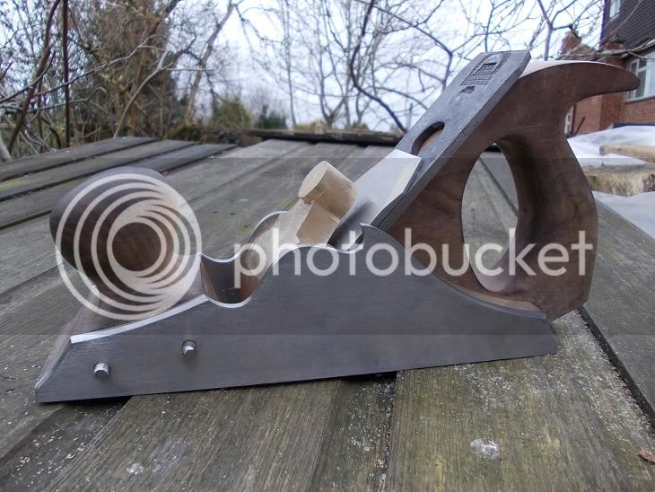
DSCN1120.JPG


...but I think that they look less aggressive and more to scale on mine...

DSCN0199.JPG


Perhaps you could check these scale against this profile shot of "SAM"....

DSCN0195.JPG


As you can see from the first picture...I have not moved on from the back yet...although the next steps are relatively easy...

The reason being is that the weather has been so very miserable...and setting up the observatory has taken all my time up so that I feel I can't concentrate on the level of care that this plane needs...along with an unfrozen brain and fingers!

However...I know the Spring will bring with it awakened enthusiasm....and ALFIE won't moan every second I'm in the shop (he doesn't like the cold!)....

Regarding the lever cap...I think it is less of an issue than you may think after doing the Scottish infill smoother...

DSCN1090.JPG


You obviously have to drill each side in the right place but that's just a crossword problem (12 across...three down...four letters beginning with "H") :mrgreen: :mrgreen:

Once you've got those equal...I just rested the finished lever cap in place....spotted the sides and drilled and tapped the holes. If you're starting out with a solid block of bronze, going in about an inch max is all that is needed.

By the way...apologies for those horrid temporary screws...would you believe I am STILL trying to source the slotted CSK bolts! I want old ones really...or old steel at least!

I'm glad you started this thread mate...gave me suitable kick up the trailing region to get big Daddy finished so we can compare notes next time we meet!

Cheers!

Jim

P.S. Nice design on that cap iron mate! Now I know what I will do with my lump of steel!
 
Thanks for that encouragement Jim, I've been frozen up too. The fingers just don't do what you tell them in the winter.

I had always been thinking about drilling the lever cap from either side but during above mentioned winter confinement I have been doing a lot of reading and web trawling and notice that the majority of Spiers and Norris planes seem to have smooth sides pointing to them having a single pivot all the way through and peined/filed invisible like the infill rivets are.
Then I remembered reading Konrad's blog - the saga of the badger and his belt and braces drilling of the skewed lever ... I will find it again later... got me thinking that maybe the Titans of old really did drill straight through the whole thing ???

Whatever; I will go with threaded pins for now and the forseeable I should think.
 
Richard T":3tpmatgh said:
Thanks for that encouragement Jim, I've been frozen up too. The fingers just don't do what you tell them in the winter.

I had always been thinking about drilling the lever cap from either side but during above mentioned winter confinement I have been doing a lot of reading and web trawling and notice that the majority of Spiers and Norris planes seem to have smooth sides pointing to them having a single pivot all the way through and peined/filed invisible like the infill rivets are.
Then I remembered reading Konrad's blog - the saga of the badger and his belt and braces drilling of the skewed lever ... I will find it again later... got me thinking that maybe the Titans of old really did drill straight through the whole thing ???

Whatever; I will go with threaded pins for now and the forseeable I should think.

Much though I admire the smooth lines of the invisible pin....I think from practical reasons I would go with countersunk bolts. I cannot think of anything more annoying than having to drill out your work 100 years from now to do some restoration when most of the ones I have worked on have been screwed here and are easy to disassemble. I'm almost an advocate for doing the same with the infills for the same reason..and I am leaving a little copperplate written note on the underside of my infills to give the future restorer a laugh many moons after I have perished! 8)

A map showing buried treasure under the local Tesco car park tickles my sense of humour for some reason! The thought of some future Time Team presenter digging up the "mother and children" section in 100 years time amuses me immensely! :mrgreen:

Jimi
 
"A map showing buried treasure under the local Tesco car park tickles my sense of humour for some reason! The thought of some future Time Team presenter digging up the "mother and children" section in 100 years time amuses me immensely! "

If only someone had done that at the time of Richard III's demise it would have saved a lot of faff.

Thanks Klaus; The spiky debate goes on but I'm pretty sure that I will never so much as snag a cardie on it.

Here, hopefully, with the lever cap in place it can be seen how out of the way they are.

DSCN1010s_zps208c1720.jpg


DSCN1014s_zps6e1520a8.jpg


I've just finished the rough filing of this and couldn't wait to see how it looked. I'm getting quicker at lever caps - just two and a half days this time.

DSCN1018s_zps6b793a88.jpg


Lots of finishing to do.
 
Some progress ... not much but some.

People who attended the sharpening do will have seen that I finally plucked up the courage to drill and rivet through the back infill and handle.


The back can stay put now but the front will have to come out again to sight the lever cap when I mark it for its pin holes.

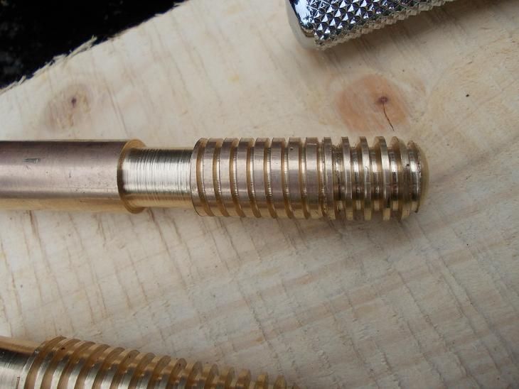
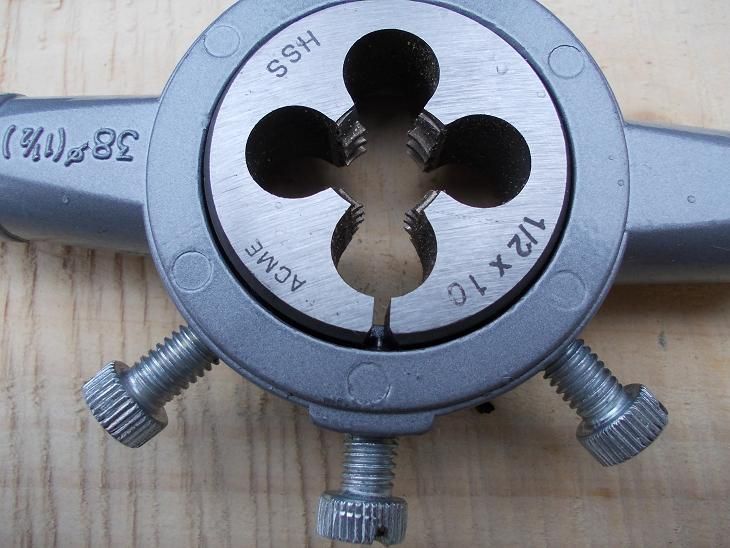
I had already drilled and tapped the lever cap screw hole and having had many speaks with Dave D of this parish (many thanks Dave) decided to go with screw cutting a partial thread onto the screw and following up with a die.


The theory being that with a split die fully opened up -


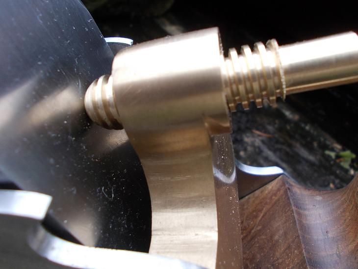
The resulting screw should be over size and subsequent adjustments to narrow the die would bring it down to a really good, tight fit but ....

it's loose. I tried again with less of a cut on the lathe to make sure I had not accidentally gone too wide or deep with the lathe tool but it's the same.

It may look good and would work I'm sure but it feels awful.


(The ripped up bit at the back of the thread was a result of forgetting to back off. #-o )

Every Norris I have twiddled moves like silk and I won't be happy until I can get my planes to the same standards.

Before anyone asks, this is supposed to be a two part screw - the head comes later. :) A steel one I should think.

So I am back to the drawing board re a good, tight acme thread. Maybe I will have to take a completely different tac.
 
How frustrating! I know you want this to be perfect, so suggestions like painting the inside of the hole are not going to be welcome...

I'm not a metalworker but I wonder if the problem is that by part-turning the thread you have taken away some metal which should have been left in place. I know this is a fairly chunky sort of thread to cut in one go, but in a world of threaded things there are loads that are bigger than 1/2". Have you tried just turning the rod to the right diameter and cutting the thread by hand? (With the die wide open for the first go, then tightened up if needed.) Surely if dies are usually used like that, it should be possible. (I know that galv steel pipes can be hand threaded in much larger sizes and surely dies would not be made in these sizes if it was not possible to just use them?)
 
Back
Top