Simple Segment Project W.I.P.

UKworkshop.co.uk

Help Support UKworkshop.co.uk:

This site may earn a commission from merchant affiliate links, including eBay, Amazon, and others.

CHJ

Established Member
Joined
31 Dec 2004
Messages
20,132
Reaction score
80
Location
Cotswolds UK
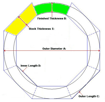
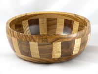
Prompted by a Thread question by woodfarmer regarding cutting segments for bowls I jumped in with some images.

I've taken the liberty of cribbing some of the material from that thread to start this W.I.P. off.

Now like all workshop projects there are no hard and fast rules of "how to do" and the following is just a rough run through of how I set about my simple segmented boxes and bowls, others will use different cutting and turning methods, indeed far more accurate and intricate segment preparation and turning skills than I will ever attempt or have the patience to master.

Hopefully the following will prompt someone new to turning to have a go, if nothing else it saves a great deal of expense on wood stock and reduces the waste wood creation considerably.

For my stuff I use a basic Chop Saw, just need to make sure everything is set up square in the vertical plane and that angles are set accurately in the horizontal.

The most important of needs is to prepare your stock for even thickness & square so that it can be cut accurately by just flipping 180deg.
 
I personally do not use abrasives when producing segments and rely totally on accuracy of cutting, I found that trying to abrade a segment is fraught with multiple chances of creating inaccuracies and a fine abraded finish is not conducive to best mechanical key for adhesive.

The Chop saw is a basic Rexon CMS.
DSCN4152 (Large).JPG

Simple and robust is often best, only want would be similar with regenerative braking to speed things up.
 

Attachments

  • DSCN4152 (Large).JPG
    DSCN4152 (Large).JPG
    68.2 KB
There is an old run-through of a lidded segmented box on my web site.
Not the way I assemble them now but it's how I started.

Decide what nominal size you want to end up with, if you construct the way I do using up scrap wood then the available diameter of the material for the base and top rim are relevant.

I use my Calculator for anything new & I have printouts for most often used, saw stops etc. are marked up with regular options.
<<<< Link
Tip:-- Don't be too critical on stock width, if you have spare then allow extra thickness in your early attempts to give yourself some error padding.

Sort out some scrap:-
DSCN4153 (Large).JPG

Run it through the saw:-
DSCN4156 (Large).JPG

Put it through the thicknesser to get it reasonable square and constant thickness:-
DSCN4157 (Large).JPG

Decide if you want contrast bands and do likewise and chop them off at the thickness you want:-
DSCN4158 (Large).JPG

Note: The use of a support media for stock that reaches over the cut path, saw plastic inserts are rarely level or rigid enough for small segment support.
DSCN4159 (Large).JPG

Adjust Chop Saw stop to segment length (allow for contrast width if used):-
Suggest you run a scrap length through to check your sizes.
Then just keep chopping away by turning the wood stock through 180 deg. until you have enough segments and a couple of spares if you have enough wood length:-
DSCN4160 (Large).JPG

The above sequence took 13 mins total according to the image EXIF files.
 

Attachments

  • DSCN4153 (Large).JPG
    DSCN4153 (Large).JPG
    117.3 KB
  • DSCN4156 (Large).JPG
    DSCN4156 (Large).JPG
    104.5 KB
  • DSCN4157 (Large).JPG
    DSCN4157 (Large).JPG
    75.7 KB
  • DSCN4158 (Large).JPG
    DSCN4158 (Large).JPG
    97 KB
  • DSCN4159 (Large).JPG
    DSCN4159 (Large).JPG
    94.6 KB
  • DSCN4160 (Large).JPG
    DSCN4160 (Large).JPG
    98.6 KB
Note:-- If you want repeatability and minimum amount of aggravation and disappointments then it is essential to set up the saw correctly.
DO NOT rely on any existing graduations or stops without checking.
I use an Engineers Set Square off a dummy piece of flat stock laid across the base to set the blade vertical and check that the vertical traverses is spot on.
For the Horizontal angles I cut stock and check it against a digital angle finder on a reference surface, you can get away with a few tenths of degree in cutting errors but you need to start as true as possible.
If you look carefully at the front right hand side of my saw (in previous image) you will see a knurled knob, this is in fact a location dowel inserted in a hole I drilled through the frame and rotating table when I had the table clamped correctly so that I can come back to the setting. (The table clamp and associated notches do not return close enough for segment work without trial and error checking)
 
Having collected your batch of segments and associated contrast fillets, if using them, it is wise to do a test clamp just to prove that nothing has gone astray, saves a lot of frustration and wasted glue just for the sake of a few extra minutes.
DSCN4161L.JPG


Note my assembly aids:-
I use a hand drill set to screw driver mode fitted with a nut driver and use the ratchet torque limiter as a vibration aid to help agitate and seat the glued segments.
A small persuader also helps ensure any segments that slip out of line or ride up off the base plain are returned to position.
 

Attachments

  • DSCN4161L.JPG
    DSCN4161L.JPG
    119.7 KB
Glue up the segments, rubbing the individual joints as you go to ensure even and good spread of adhesive.
DSCN4163L.JPG
 

Attachments

  • DSCN4163L.JPG
    DSCN4163L.JPG
    122.8 KB
First one glued and clamped:-
DSCN4164L.JPG


And the second one assembled and both ready to be put on one side for glue to cure.
DSCN4165L.JPG


I use Cascamite adhesive, mainly because it does not have joint creep as PVA can with wood/humidity movements.

As a time indicator:-- from the shot of the test clamping to complete glue-up including adhesive measuring/mixing was according to the EXIF data 27min.
 

Attachments

  • DSCN4164L.JPG
    DSCN4164L.JPG
    124.2 KB
  • DSCN4165L.JPG
    DSCN4165L.JPG
    129.7 KB
Thanks, this has been really useful. I have turned segmented bowls before, a long time ago, but the blanks were pre-made. I hope to get most of the timber for the segments from short (2-3 feet long logs) mostly oak, some ash, acacia and the odd fruit wood. All will be rescued from my firewood pile :)

I notice that your original diagram showed 8 segments but the workpiece shows 12. I am assuming that it is easier to make bigger bowls by using the greater number of segments. I appreciate that length of segments and any contrasting (or not) straight pieces also affects the size.

Is there any general rule relating size to number of segments?

regards
 
woodfarmer":1aqgvnkz said:
....I notice that your original diagram showed 8 segments but the workpiece shows 12. I am assuming that it is easier to make bigger bowls by using the greater number of segments. ...
Is there any general rule relating size to number of segments?

Obviously the smaller the number of segments the thicker the stock needs to be and more wood will have to be turned off.

It's a matter of personal preference, I just find that 12 looks better proportioned to me for my small boxes.
I used 24 segments for this bigger Bowl:-
smDSCN3147.JPG
 
Next comes the preparation of the glued segments and the top and bottom pieces for final glue up.

The first image is a bit gratuitous to this process but it shows how I consolidate time use when machines are in use and prepare stock volume when time permits.
DSCN4166L.JPG


The glued segment sections and rough blanks selected for tops and bottoms.
DSCN4167L.JPG
 

Attachments

  • DSCN4166L.JPG
    DSCN4166L.JPG
    132.2 KB
  • DSCN4167L.JPG
    DSCN4167L.JPG
    103.2 KB
First task in preparation for final glue-up.

Mount segment ring for clean -up.
DSCN4168L.JPG


Warning:- Always clamp in compression, finding out that a glue joint is not sound or wood structure weak whilst cutting when mounted in expansion is not a procedure to be encouraged.

Note:- Cascamite recommends caution when components are to be machined and allow 48 hrs or so before subjecting to heavy cutting loads, I have never had a joint fail with items cured overnight at domestic room temperature but like many of my other tasks I tend to do glue ups in batches and rough assemblies are more often than not lying around for days,weeks, or months even. So if you are gluing up in an unheated shed be cautious.

I do a lot of my roughing out turning by using tools in a boring mode, much the same as if using a pattern makers or metal lathe.
DSCN4169L.JPG
DSCN4170L.JPG


If you don't have a carbide tipped tool then a stiff sharp 1/2" scraper can be used in the same mode.
 

Attachments

  • DSCN4168L.JPG
    DSCN4168L.JPG
    125.6 KB
  • DSCN4169L.JPG
    DSCN4169L.JPG
    125.3 KB
  • DSCN4170L.JPG
    DSCN4170L.JPG
    86.4 KB
With a sharp flat scraper finish off the mating surface:-
DSCN4171L.JPG


Check for flatness across the diameter with a steel rule, if you have it near you will get a squeak if the rule is presented as the lathe slows down, you'll know when you get a perfect one the squeak is unmistakable.
DSCN4172L.JPG


Turn the piece around and complete the other side:-
DSCN4173L.JPG
DSCN4174L.JPG


Do likewise for any other segments whilst you have the chuck mounted:-
DSCN4175L.JPG
 

Attachments

  • DSCN4171L.JPG
    DSCN4171L.JPG
    118.5 KB
  • DSCN4172L.JPG
    DSCN4172L.JPG
    122 KB
  • DSCN4173L.JPG
    DSCN4173L.JPG
    114.4 KB
  • DSCN4174L.JPG
    DSCN4174L.JPG
    110.2 KB
  • DSCN4175L.JPG
    DSCN4175L.JPG
    114.6 KB
Now to sort the tops and bottoms out whilst we still have these jaws/chuck mounted.

Take a base piece and mount:-
DSCN4176L.JPG

Roughly true up the face and edge as far as possible.
Mark out for and cut a recess mounting socket to suit your jaws. (I always use my simple gauges)
DSCN4177L.JPG

DSCN4178L.JPG

And do the same for any other bases you have ready.
DSCN4179L.JPG
 

Attachments

  • DSCN4176L.JPG
    DSCN4176L.JPG
    103.2 KB
  • DSCN4177L.JPG
    DSCN4177L.JPG
    100.4 KB
  • DSCN4179L.JPG
    DSCN4179L.JPG
    112.4 KB
  • DSCN4178L.JPG
    DSCN4178L.JPG
    97.7 KB
Mount the top piece and rough true, mark the basic joint dimensions from the segment ring:-
DSCN4180L.JPG


True up the mating surface much the same as you do the segments, note the undercut central area, more on that later:-
DSCN4181L.JPG

And repeat for any other tops:-
DSCN4182L.JPG
 

Attachments

  • DSCN4180L.JPG
    DSCN4180L.JPG
    107.6 KB
  • DSCN4181L.JPG
    DSCN4181L.JPG
    107.1 KB
  • DSCN4182L.JPG
    DSCN4182L.JPG
    114.4 KB
Swap Jaws or in my case Chucks:-
DSCN4183L.JPG


Mount the base and prepare the mating ring and clean out any base recess:-
DSCN4184L.JPG
DSCN4185L.JPG

The above turning sequences took 49 mins total according to the image EXIF files.

The turning tools I've used so far:-
DSCN4186L.JPG
 

Attachments

  • DSCN4183L.JPG
    DSCN4183L.JPG
    127.4 KB
  • DSCN4184L.JPG
    DSCN4184L.JPG
    108.8 KB
  • DSCN4185L.JPG
    DSCN4185L.JPG
    108.1 KB
  • DSCN4186L.JPG
    DSCN4186L.JPG
    196 KB
Now for the reason I suggest you have a slight recess in the top portion.
Should you have a significant delay in gluing up the assembly there is a chance that the top and bottom will move, also if you are less than sure about the flatness of the joint surfaces you can recover things:-

Using a large sheet of abrasive on a flat surface, I use a spare 250mm disc sander disc, dress the joint surfaces:-
DSCN4187L.JPG

If you run some pencil lines across before you start you will soon see if the surface is flat:-
DSCN4188L.JPG


Warning:- Do not attempt to use a disc or belt sander for the above routine, you WILL make a mess of the mating surface and not get it flat enough for a minimum joint line.
Even with hand lapping take care that the abrasive is flat and not curled away from the support at all.
 

Attachments

  • DSCN4187L.JPG
    DSCN4187L.JPG
    89.8 KB
  • DSCN4188L.JPG
    DSCN4188L.JPG
    74.5 KB
Ready for glue up, the pieces do not have to be exactly the same diameter at this stage but if you have a reasonably close match near the mating surfaces it helps in alignment whilst clamping.
DSCN4189L.JPG


Apply the glue and ring the components together as you proceed to even out the glue spread, and clamp firmly:-
DSCN4190L.JPG

Check component alignment before maximum pressure is applied, they have a perverse tendency to slide sideways and once fully clamped it may be difficult to break the seal and move.

Dependant upon size of assembly and wood stiffness (i.e. using thinner stock) you may need to use multiple clamps around the periphery or a scrap spreader piece to ensure an even and close join line.
 

Attachments

  • DSCN4189L.JPG
    DSCN4189L.JPG
    102.9 KB
  • DSCN4190L.JPG
    DSCN4190L.JPG
    108.1 KB
Back
Top