Short of leaning on it......

UKworkshop.co.uk

Help Support UKworkshop.co.uk:

This site may earn a commission from merchant affiliate links, including eBay, Amazon, and others.

bobbydazzler

Member
Joined
28 Feb 2011
Messages
18
Reaction score
0
Location
Upper Teesdale County Durham
.....does anyone know if a 2.6 metre 50mmx50mmx3mm steel box section will sag in the middle (under moderate pressure)?

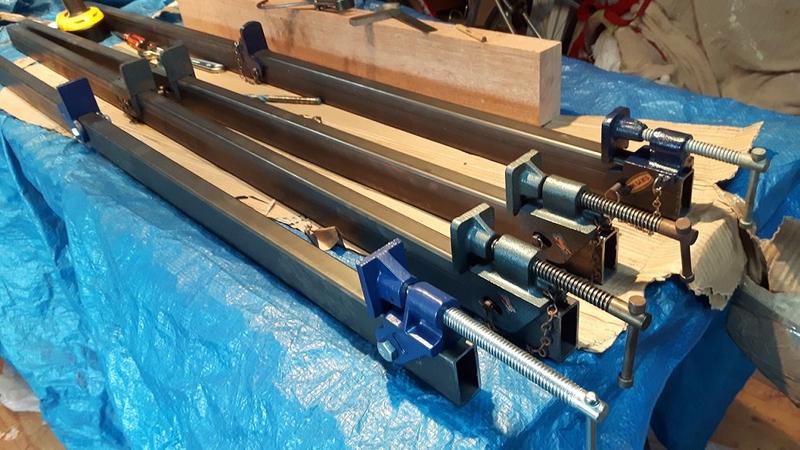
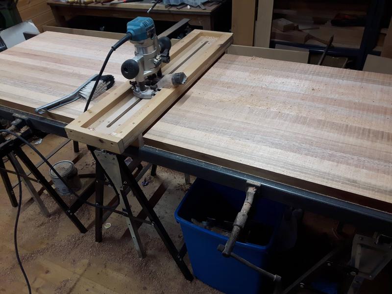
I should explain....I'm gonna install a 3 metre wide (I know, too much stuff) by 800mm deep PC desk/bench made from two pieces of high density (?) 1.5Mx800mmx25mm chipboard (yuk). I'll have to join these in-situ, due to limited access, with glue plus 4 butterfly clamp bolts.

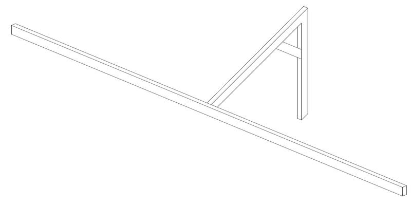
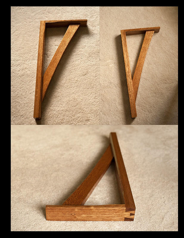
It'll be supported at the back with a wall batten. I hope to get away with insetting the two legs at the front (can't have more) by around 200mm....but this still gives me a span (or apron if you will) of 2.6 metres.....hence the question.

I can hide the steel box section behind a false wood apron.

While I'm at it I'll also make the two legs out of the same steel and weld all three pieces up (not in situ I hasten to add :))

Any advice most gratefully received!
 
At some level of microscopy, everything that spans sags! :D So it's much more a question of what your tolerances are.......and, of course, what your loads are. But under normal domestic desk loads, without sitting a fish tank and a filing cabinet on it at mid-span, that looks like overkill to me. Personally I'd be happy with much lighter steel than that (and you don't need it to be square, either, as the forces are only downwards........you could use a 2x1 box section). 'twere it me, though, I would be using some of that steel to make a bracket to take the loads back to the wall at mid-span.
 
bobbydazzler":2xe19gm4 said:
In your last statement do you mean a steel support that angles back from the mid section to the wall? I have me knees to consider! ;)

No, a right angle. If your knees clear the front edge support steel, they'd clear a right angle bracket. You could strengthen it somewhat with a small gusset, but your desk-thingy is 800 wide, and you'd need to be 11 feet tall to have knees reach the back.
 
Hi Bob

You said you do welding, why not put a bow into it "metal rod" between your 2 strong points and tie your 3 centres, provided you have 200mm above or below your apron, and no sag.
 
Echo-Star":1s471idk said:
Hi Bob

You said you do welding, why not put a bow into it "metal rod" between your 2 strong points and tie your 3 centres, provided you have 200mm above or below your apron, and no sag.

Not sure I get your meaning here Echo.....could you expand on this?

Many thanks for the advice guys!!
 
I would think a shallow arc would guarantee no central sag. Think arched bridge but with the ends of the arch meeting the legs maybe 15 or 20c down. This will be more rigid and possibly more elegant too.
 
I reckon you could get away with using 50 mm strips of 18mm ply, maybe two or three laminated together and then glued to the front edge underneath the desk, although I bow to the superior knowledge of any structural engineers out there. If you did make it slightly bowed as AJB suggested I reckon it'd be more than strong enough.
 
Thanks fellas (apologies if any of you are ladies!).....the difficulties in creating an arc (in the steel) are beyond my ken I'm afraid (heating it would lose it's temper....and probably mine as well) but it's a great idea and one that would surely work.

The laminate ply also has promise.....and I can get some really cheap (if they haven't already been snapped up!)

Hmmmmm.....
 
I built a similar desk in my previous house, the span wasn't quite as wide though. Probably about 2.4m. It had a length of 25x25x2mm box section running underneath the front edge. It was supported in the middle by two legs spaced about 400mm apart to allow a pedestal cabinet between them. That was strong enough to sit on without sagging. I think 50x50x3 is a bit overkill. 25x50x2 would probably be stiff enough. That's the kind of size used in most office furniture.

To double check, here's a sag calculator:

https://www.engineering.com/calculators ... htm#hollow
 
steel beam deflection.jpg
I should thank the OP for this post as it made me go to youtube and follow the example of using Freecad and it's FEM module.I have felt I ought to be learning this sort of thing for a while and it wasn't too hard to create a steel box of the specified length and wall thickness.Finding how to mesh the object,select a material (generic steel) and apply fixed constraints and self weight constraints was a useful experience.As can be seen in the attached screenshot there isn't much from the weight of the beam.I will have a bit of a play for my own education in the form of adding loads but I find it incredible that this kind of software is available for no cost.I think we can all benefit from the efforts of the developers.
 

Attachments

  • steel beam deflection.jpg
    steel beam deflection.jpg
    144 KB · Views: 130
If it helps to visually appreciate it, the following are 25 x 500 x 3 mm box section I used for making sash cramps. From memory the cramps are maybe 1500 long (bit more/less mebbe?). They are heavy in use. You know you're picking one up put it that way. At this length I'm fairly sure you'd need industrial tools to bend them to any noticeable degree. To human eye at least I cant see any movement cinched as tight as I can muster for real life purposes (as cramps).

nWH67FQ.jpg


When I bought them I cut them to useable lengths apart from two which I kept back as provision for making super long cramps for doors. :roll:
I've yet to finish the house never mind make the bloomin' doors.
So the only pic I have of the other 2400 original lengths in use is this.

BkIRHtp.jpg


Used for flattening the benchtop with a router jig.
I'm about 10 stone give or take with Chrismas. :-"
So to prove there's more than one approach to skinning a cat...

I'd say with proper scientific abandon... Let's do a theoretical walky/bendy test. Empirical of course. :D
If you lent the long lengths at about 45 deg on the floor and a solid surface......
25mm side down:
I reckon I could walk up it without much movement other than my balletic grace getting excited murmurs from the Strictly Ballroom Judges.
You wouldn't get a lot of bend. Except maybe from the Judges. 8)
500 side down:
Still take my weight. 60- 70kg bouncing in the middle would move it as (overtly) dynamic force but not a huge amount unless I was desperate to prove a point. I could walk up it with a small amount of bow I'd guess. In a static loading situation reinforced structurally and braced at the mid section I reckon you'd be mad to go for 500x 500.

Its Science isn't it.

(With Huge apologies to Worn Thumbs! :D)
Cheers
Chris
 
What a wonderful forum this is!

Don't think I've ever come across such helpful and generous people (but then again I don't get out much ;))

From all that's been said I don't think I'll go far wrong with a 2.6M section of 50mmx25mmx3mm......legs bolted either end (can't weld it up AND get it in the room it's intended for)

Plenty of bracing obviously (every 400mm or so) extending to the back wall batten and pehaps an angle piece like Mike suggested!

Once again, many thanks chaps!
 
Learning finite element analysis for this problem is serious overkill - I wouldn't recommend it unless you find it an interesting hobby! All you need for beam deflection is Euler-Bernoulli beam theory. Solutions for common usage cases of cantilever and simply supported beams are widely available, for example here: https://en.m.wikipedia.org/wiki/Deflection_(engineering)#Beam_deflection_for_various_loads_and_supports

Sent from my SM-N910F using Tapatalk
 
Back
Top