Mirboo
Established Member
I recently took delivery of one of the new Lie-Nielsen small router planes. My first impressions of the little plane are documented in the review that follows. I hope you find it a worthwhile read.
Packaging
The Lie-Nielsen 271 small router plane arrived inside the usual brown cardboard Lie-Nielsen Toolworks box. Unusually, the plane specific printing that ordinarily appears on the end of a Lie-Nielsen plane box was in this case replaced by a sticker stating the model number of the plane. I can only assume that the small router plane boxes aren’t printed yet and that this stickered version will be superseded once they are. Inside the box were the plane, a small leaflet stating that this particular plane was one of the first 100 No. 271 router planes produced by Lie-Nielsen Toolworks and an even smaller leaflet explaining the dangers of brass and bronze due to the lead present in both alloys (Fig. 1). The warning leaflet is required for compliance with laws in the US state of California and explains that after handling brass or bronze you should wash your hands. This is all well and good, but what if the water taps over my wash basin are brass, what do those Californian legislators suggest I do then?
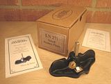
Figure 1 – The box and its contents.
The plane itself was wrapped in white butcher’s paper and sealed inside a blue plastic bag. This method of wrapping appears to have replaced the Ferro-Pak paper wrapping that used to be the standard for items shipped from Lie-Nielsen Toolworks.
There was no instruction leaflet included with the plane which is not typical of products from Lie-Nielsen. I expect that instruction leaflets will ultimately be provided with the planes but, as with the boxes, these haven’t yet returned from the printer.
Form
The little Lie-Nielsen router plane shares the number 271 with the small router plane once produced by Stanley in significant numbers (Fig. 2). This designation and the ¼-inch blade width are about where the similarities between the Lie-Nielsen and Stanley routers end. Lie-Nielsen makes the claim via their website that the plane is loosely based on the Stanley 271, very loosely I’d say.

Figure 2 – Stanley 271 Small Router Plane. (Source: The Old Tool Shop)
The Lie-Nielsen 271 actually bears a striking resemblance to the Phelps small router plane (Fig. 3). The Lie-Nielsen and the Phelps are not identical, but the designs of the two planes are undeniably similar. The Phelps Manufacturing Company was a USA based tool producer operating from around 1933 until 1947.

Figure 3 – Phelps Small Router Plane. (Source: Lars Larson's Metal Router Plane Type Study)
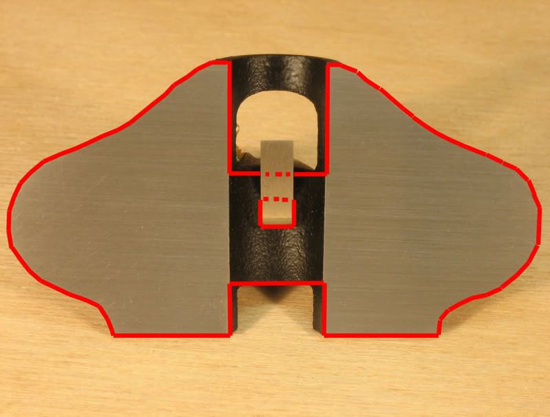
The profile of the sole of the Lie-Nielsen 271 (Fig. 4) very closely resembles a scaled down version of the sole of the Stanley 71. (Fig. 5) Both the Lie-Nielsen 271 and the Stanley 71 have an open throat configuration. The only picture I have seen of the yet to be released large Lie-Nielsen router plane (Fig. 6) suggests that it too will closely resemble the Stanley 71. Therefore, my guess is that one of the reasons Lie-Nielsen designed their 271 the way they did is so that there will be a family resemblance between the large and the small Lie-Nielsen router planes.
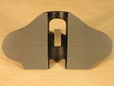
Figure 4 – Sole of the Lie-Nielsen 271.
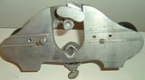
Figure 5 – Sole of the Stanley 71. (Source: Handplane Central)

Figure 6 – The yet to be released large Lie-Nielsen router plane. (Source: Ron at Wood Central)
The composition of the plane body and the blade is not specified on the Lie-Nielsen website and the absence of any instruction leaflet with the plane means that these details remain unclear. I can only assume that the Lie-Nielsen 271 shares DNA with other Lie-Nielsen hand planes and has a ductile cast iron body and an A2 tool steel blade. This would be a fairly safe bet in my view. A knurled and slotted brass thumbscrew is used to hold the blade in position.

Figure 7 – Components of the Lie-Nielsen 271 small router plane.
Lie-Nielsen reports that the 271 is approximately 4" x 2" and weighs 0.55 lbs. I can kind of relate to inches, but being the post metric kid that I am, pounds mean nothing to me. I felt compelled to take some measurements of my own.
The cast body of the plane is 105mm wide, 54mm long and 21.5mm high. (I’m using width here to describe the dimension that is transverse to the normal direction of travel of the plane in use.) The height measurement was taken to the top of the blade clamp after the blade had been removed. With the plane sitting on a flat surface, the distance from that surface to the underside of the little arch that forms the open mouth of the router is 8mm. The diameter of the knurled portion of the brass blade clamping thumbscrew is 12.5mm.

Figure 8 – Lie-Nielsen 271 Small Router Plane.
I measured a mass of about 210 grams when I weighed the fully assembled plane on my kitchen scales (hardly the most accurate instrument in the world).
Patrick Leach, of Blood & Gore fame, reports that the Stanley 271 has a width of 3 inches and weighs 3/8 lbs (There’s those pesky pounds again, and fractions too). The Lie-Nielsen is therefore wider and heavier than the Stanley.
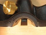
Figure 9 –The open mouth of the Lie-Nielsen 271 small router plane (front view).
The design of the Lie-Nielsen 271 is such that there is no sole area whatsoever along the centre line of the plane (Figs. 4 & 9). Here it differs from both the Stanley 271 (Fig. 10) and the Record 722 (Fig. 11). I measured the width of the centre channel on the Lie-Nielsen to be 18mm.
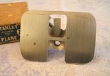
Figure 10 – Stanley 271 Small Router Plane. (Source: Handplane Central)
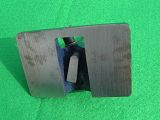
Figure 11 – Record 722 Small Router Plane. (Source: Peter Hanman Tools)
As has already been mentioned, the blade of the Lie-Nielsen 271 is ¼-inch wide. Further measurements reveal that the leading edge of the blade (the bevel) projects 19mm forward of the rear of the blade post. The vertical measurement from the tip of the blade to the top of the blade post, with the blade installed in the plane, is 54mm and the post is 6.3mm (¼-inch) square. All of the edges and corners of the blade post, along the length of the post and around the top, have been slightly relieved so that there are no annoying sharp edges that might cut into an unsuspecting hand or finger.
The Lie-Nielsen Toolworks website reports that optional 1/16-inch square tipped and pointed blades for inlay work will be available soon.
Four blade configurations are possible with the little Lie-Nielsen thanks to the square blade post. There is the normal blade orientation where the foot of the blade points towards the little arched portion (the open mouth) of the sole. For illustrative purposes we’ll call this normal orientation “north”. Reversing the direction of the blade (south) allows the so called bullnose configuration to be used. Finally, the blade can be oriented at 90 degrees either left or right of the center channel (east and west), although usage of the plane with the blade in these positions would be quite limited. The blade cannot be retracted into the body when the blade is installed in either the east or west positions, nor is there provision for chip clearance in these positions. Visibility of the work piece is also virtually non-existent with the east and west orientations. You never know though, someone might come up with an application for which the ability to mount the blade either east or west is quite useful.

Figure 12 – Bullnose configuration.
Figure 12 shows that with the plane set in the bullnose configuration, the sole of the Lie-Nielsen 271 projects further than the tip of the blade. The Stanley 271, shown in bullnose configuration in Figure 2, is similar in this respect.
Maximum blade projection, with the top of the post set flush with the top of the blade clamp, is 27.5mm.
My impression of the Lie-Nielsen 271 is that it is a quality little tool. The components, all three of them (Fig. 7), look well made and are nicely finished. But how does it perform?
Function
The blade of the little Lie-Nielsen 271 was already quite sharp straight out of the box. Before putting it into action I polished the bottom of the blade (the sole of the foot) and honed the bevel on an 8000 grit Norton waterstone. This was a fairly quick and easy operation because the blade was quite well finished from the factory and its relatively small size meant that there was not much blade area that had to be worked on the stone.
My first test for the Lie-Nielsen 271 was to cut a recess for a 25mm brass butt hinge on the edge of a 12mm thick length of Tasmanian Oak. The timber sold in Australia as Tasmanian Oak is a hardwood that can be any of three similar eucalypt species. Early European timber workers called these species Tasmanian Oak because they believed that the timber was of a similar strength to English Oak.
I started by scribing the dimensions of the recess, using a wheel type marking gauge and a marking knife, onto the edge of the piece of Tassie Oak. The Lie-Nielsen 271 was then put into action removing the waste material to form the recess, working across rather than along the piece of Tassie Oak as shown in Figure 13.
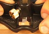
Figure 13 – Cutting the recess for a small butt hinge.
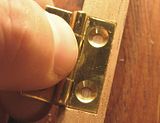
Balancing the little Lie-Nielsen router on the 12mm wide edge of the piece of wood did not present a problem. I completed the recess using three passes of the router plane, resetting the blade deeper after each pass until on the final pass the blade depth matched the thickness of one leaf of the hinges. I re-scribed the edges of the recess after each of the first two passes. With the plane sitting on a flat surface and a hinge leaf placed beneath the front and back as shown in Figure 14, setting the depth of cut for the final pass was a simple matter of releasing the blade clamping thumbscrew, lowering the tip of the blade onto the flat surface and re-clamping. Finger tightness was sufficient to hold the blade at the desired setting.
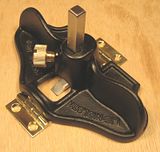
Figure 14 – Setting depth of cut for installation of butt hinges.
Surprisingly, to me at least, the open mouth configuration of the plane proved advantageous while cutting the recess. Figure 13 above shows the plane poised for the second cut of the first of three passes. The first cut, made adjacent to the knifed border of the recess, has raised a chip that is still attached on the side opposite the knifed line. The open mouth means that this chip, which would interfere with the passage of the second cut of a closed mouth plane, does not cause any interference at all. Prior to the third cut of the pass it was necessary for me to remove the raised chip because by this stage it had become too large to pass through the open mouth of the plane. After removing the chip, I simply pulled it off with my fingers, little raised dags were still present but these could pass though the open mouth without hindering the smooth passage of the plane.
The little router allowed me to complete a recess of accurate depth in a much more controlled manner than the chisel wielding methods I had previously employed. (Figs. 15 & 16)
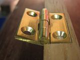
Figures 15 & 16 – Completed hinge recess.
Cleaning up the bottom of a shallow mortice, cut lengthwise into the edge of a piece of 19mm by 42mm radiata pine, was the next task to which I put the little router plane. A 3/8-inch mortice chisel was used to cut the mortice and then I used the plane to clean up the bottom. The mortice was approximately 8mm deep. This task highlighted what I think is one of the disadvantages of the open mouth configuration of the plane. You will recall that there is no sole area whatsoever along the centre line of the plane and that the width of this unsupported area is 18mm. The 19mm thick edge into which I had cut the mortice meant that there was virtually no support for the plane to do its job. Clamping a piece of scrap to either side of the piece being morticed (Fig. 17) was a quick way of getting around this problem but it obviously adds another process to the task which is not ideal. I would expect the design of the Stanley 271, with two small sole areas across its centre section (Fig. 10), and to a lesser extent the Record 722, which has one small area of support across the centre (Fig. 11), to be able to complete this task without having to clamp scrap in place to provide support. Note though that I haven’t used a Stanley 271 or a Record 722 so this is just supposition on my part.
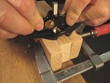
Figure 17 – Pieces of scrap clamped in place to provide support for the plane.
With the scrap clamped in place the plane was an effective tool for quickly cleaning up the bottom of the mortice.
The 19mm length of the ‘foot’ of the blade of the Lie-Nielsen 271 means that a mortice needs to be at least 38mm long if you want to be able to access the entire bottom of the mortice with the router plane. Inside a mortice less than 38mm long the back of the blade post contacting the end of the mortice will make it impossible to reach the middle of the mortice with the cutting tip of the blade.
I found that setting the plane blade was aided by the square blade post. The lateral orientation of the blade is fixed once the square blade post is inserted into its square hole and then depth of cut becomes the only consideration.
In use the slight “S” shape of the handles of the router plane provides a very comfortable grip when pushing the plane with the blade set in the normal position. The curve of the handles guided my thumbs to a position towards the centre of the plane and my fingers to a position closer to the edges (Fig. 18). This grip affords good control of the plane. Pushing the plane with the blade set in the bullnose position was not quite so comfortable and didn’t feel as natural. In this case the curvature of the handles produced a grip where the positions of my thumbs and fingers were reversed (Fig 19). I found that the most comfort and control was achieved by pushing the plane when the blade was set in the normal position and pulling the plane when the blade was set in the bullnose position.
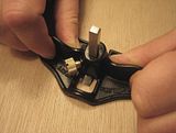
Figure 18 – Grip for pushing the plane with the blade set in the normal position.
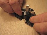
Figure 19 – Grip for pushing the plane with the blade set in the bullnose position.
In my opinion the single blade hole of the Lie-Nielsen 271 is an improvement over the Stanley 271. With the Lie-Nielsen you only have to loosen the thumbscrew to change the blade configuration from normal to bullnose. With the Stanley you have to remove the thumbscrew from one hole and re-install it another. Aside from being a pain, this presents the risk of dropping and losing the thumbscrew or if you’re a real klutz, cross threading it upon re-installation. The design of the Lie-Nielsen eliminates these problems without the more complicated drawbolt arrangement of the Record 722. While still having two blade holes like the Stanley 271, the Record 722 eliminates the need to remove and re-install the thumbscrew through the use of a single drawbolt that can grip the blade in either position (Fig. 20).
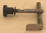
Figure 20 – Drawbolt for locking the blade of a Record 722. (Source: BugBear's Pages)
Conclusion
The Lie-Nielsen 271 is a quality little plane. It is solid and well finished. The open mouth configuration of the plane has its pros and cons but nothing that can’t be worked around. Other aspects of the plane’s design, namely the square blade post, the single blade hole and the shape of the handles, are in my view improvements over previous designs.
Lie-Nielsen Toolworks in Maine will sell you one of their small router planes for the sum of US$75. This price does not include postage, import duties or taxes should they apply. When you consider what some second hand tool dealers charge for vintage small router planes I think the price of the Lie-Nielsen is quite reasonable, of course you could pick up a vintage Stanley 271 or Record 722 for a lot less via eBay or at a flea market or car boot sale.
At the time of writing this review I could not find the small router on Axminster’s Lie-Nielsen website so I’m not sure what price will be charged in the UK.
Readers of this review will have to decide for themselves whether or not they think that the Lie-Nielsen 271 is worth the money. In my case I am confident that it will be a useful addition to my hand tool kit and will perform the tasks I had in mind for it when I placed my order.
References
Lie-Nielsen Toolworks Inc.
Lars Larson's Metal Router Plane Type Study
Patrick's Blood & Gore
BugBear's Pages
Fine Print
I have no affiliation whatsoever with Lie-Nielsen Toolworks Inc. I purchased the Lie-Nielsen 271 small router plane with my own funds. I am a bit of a fan of Lie-Nielsen hand tools, and own a few of their products, but I have tried not to let this cloud my judgement. I have tried to offer a fair and considered opinion of the plane. You can decide for yourself whether or not you think I’ve achieved this goal.
Packaging
The Lie-Nielsen 271 small router plane arrived inside the usual brown cardboard Lie-Nielsen Toolworks box. Unusually, the plane specific printing that ordinarily appears on the end of a Lie-Nielsen plane box was in this case replaced by a sticker stating the model number of the plane. I can only assume that the small router plane boxes aren’t printed yet and that this stickered version will be superseded once they are. Inside the box were the plane, a small leaflet stating that this particular plane was one of the first 100 No. 271 router planes produced by Lie-Nielsen Toolworks and an even smaller leaflet explaining the dangers of brass and bronze due to the lead present in both alloys (Fig. 1). The warning leaflet is required for compliance with laws in the US state of California and explains that after handling brass or bronze you should wash your hands. This is all well and good, but what if the water taps over my wash basin are brass, what do those Californian legislators suggest I do then?
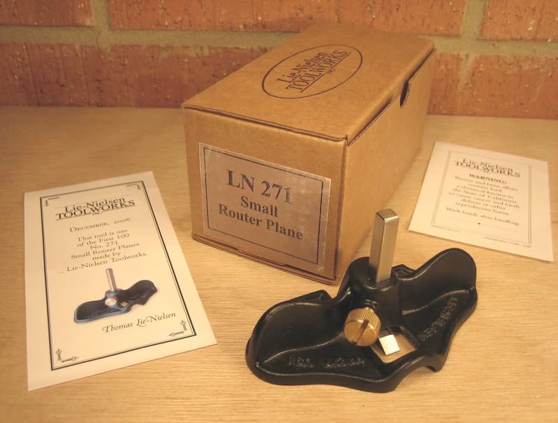
Figure 1 – The box and its contents.
The plane itself was wrapped in white butcher’s paper and sealed inside a blue plastic bag. This method of wrapping appears to have replaced the Ferro-Pak paper wrapping that used to be the standard for items shipped from Lie-Nielsen Toolworks.
There was no instruction leaflet included with the plane which is not typical of products from Lie-Nielsen. I expect that instruction leaflets will ultimately be provided with the planes but, as with the boxes, these haven’t yet returned from the printer.
Form
The little Lie-Nielsen router plane shares the number 271 with the small router plane once produced by Stanley in significant numbers (Fig. 2). This designation and the ¼-inch blade width are about where the similarities between the Lie-Nielsen and Stanley routers end. Lie-Nielsen makes the claim via their website that the plane is loosely based on the Stanley 271, very loosely I’d say.
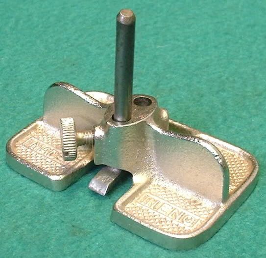
Figure 2 – Stanley 271 Small Router Plane. (Source: The Old Tool Shop)
The Lie-Nielsen 271 actually bears a striking resemblance to the Phelps small router plane (Fig. 3). The Lie-Nielsen and the Phelps are not identical, but the designs of the two planes are undeniably similar. The Phelps Manufacturing Company was a USA based tool producer operating from around 1933 until 1947.

Figure 3 – Phelps Small Router Plane. (Source: Lars Larson's Metal Router Plane Type Study)
The profile of the sole of the Lie-Nielsen 271 (Fig. 4) very closely resembles a scaled down version of the sole of the Stanley 71. (Fig. 5) Both the Lie-Nielsen 271 and the Stanley 71 have an open throat configuration. The only picture I have seen of the yet to be released large Lie-Nielsen router plane (Fig. 6) suggests that it too will closely resemble the Stanley 71. Therefore, my guess is that one of the reasons Lie-Nielsen designed their 271 the way they did is so that there will be a family resemblance between the large and the small Lie-Nielsen router planes.
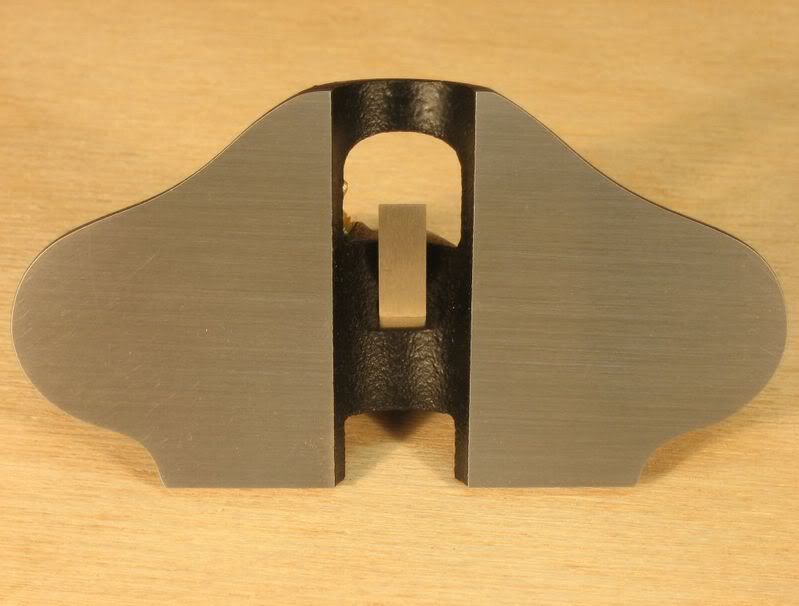
Figure 4 – Sole of the Lie-Nielsen 271.
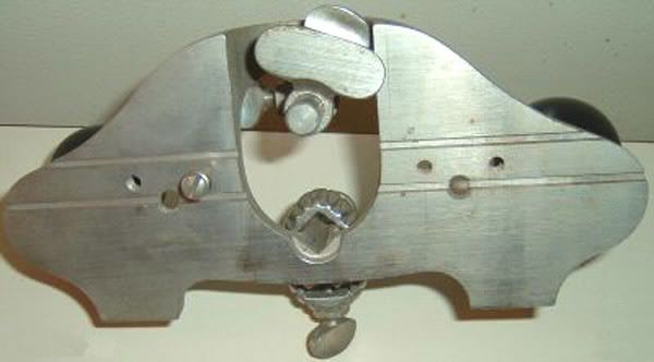
Figure 5 – Sole of the Stanley 71. (Source: Handplane Central)
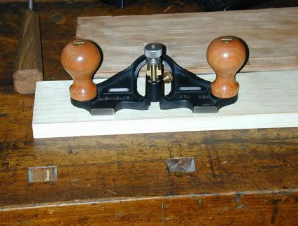
Figure 6 – The yet to be released large Lie-Nielsen router plane. (Source: Ron at Wood Central)
The composition of the plane body and the blade is not specified on the Lie-Nielsen website and the absence of any instruction leaflet with the plane means that these details remain unclear. I can only assume that the Lie-Nielsen 271 shares DNA with other Lie-Nielsen hand planes and has a ductile cast iron body and an A2 tool steel blade. This would be a fairly safe bet in my view. A knurled and slotted brass thumbscrew is used to hold the blade in position.
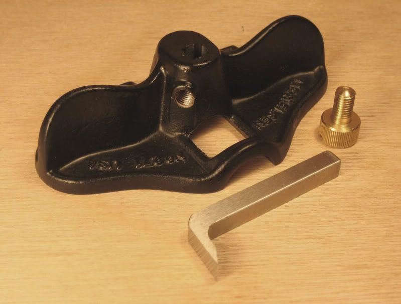
Figure 7 – Components of the Lie-Nielsen 271 small router plane.
Lie-Nielsen reports that the 271 is approximately 4" x 2" and weighs 0.55 lbs. I can kind of relate to inches, but being the post metric kid that I am, pounds mean nothing to me. I felt compelled to take some measurements of my own.
The cast body of the plane is 105mm wide, 54mm long and 21.5mm high. (I’m using width here to describe the dimension that is transverse to the normal direction of travel of the plane in use.) The height measurement was taken to the top of the blade clamp after the blade had been removed. With the plane sitting on a flat surface, the distance from that surface to the underside of the little arch that forms the open mouth of the router is 8mm. The diameter of the knurled portion of the brass blade clamping thumbscrew is 12.5mm.
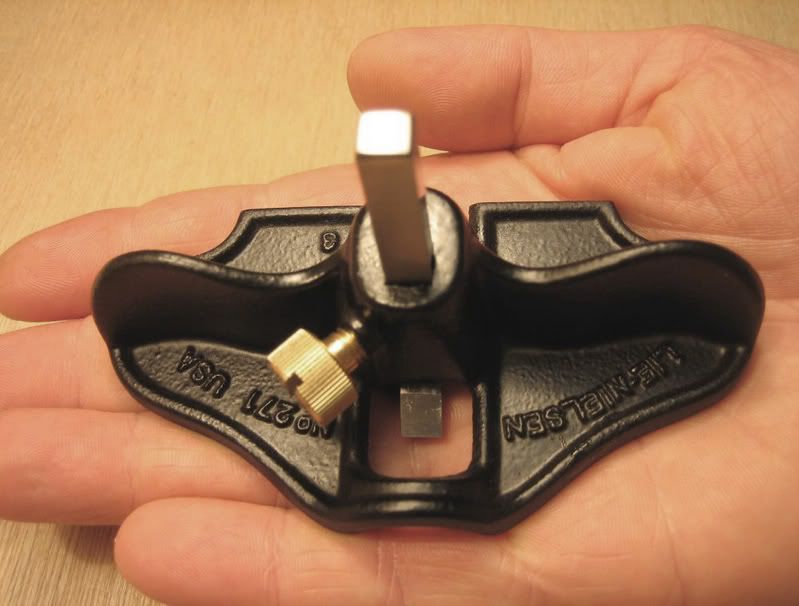
Figure 8 – Lie-Nielsen 271 Small Router Plane.
I measured a mass of about 210 grams when I weighed the fully assembled plane on my kitchen scales (hardly the most accurate instrument in the world).
Patrick Leach, of Blood & Gore fame, reports that the Stanley 271 has a width of 3 inches and weighs 3/8 lbs (There’s those pesky pounds again, and fractions too). The Lie-Nielsen is therefore wider and heavier than the Stanley.
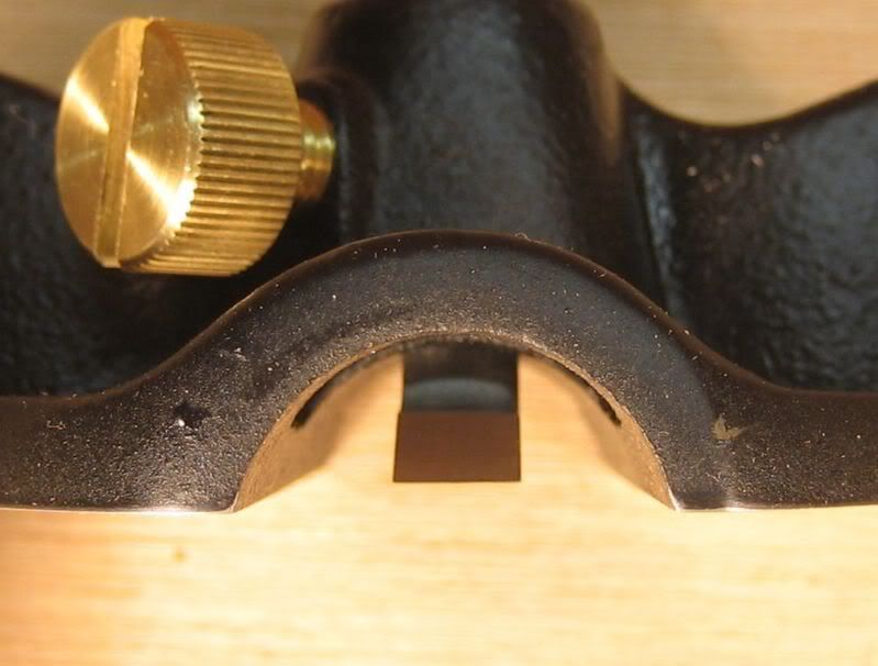
Figure 9 –The open mouth of the Lie-Nielsen 271 small router plane (front view).
The design of the Lie-Nielsen 271 is such that there is no sole area whatsoever along the centre line of the plane (Figs. 4 & 9). Here it differs from both the Stanley 271 (Fig. 10) and the Record 722 (Fig. 11). I measured the width of the centre channel on the Lie-Nielsen to be 18mm.
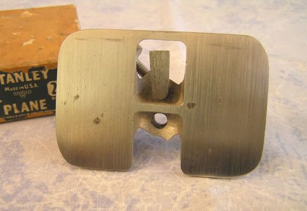
Figure 10 – Stanley 271 Small Router Plane. (Source: Handplane Central)

Figure 11 – Record 722 Small Router Plane. (Source: Peter Hanman Tools)
As has already been mentioned, the blade of the Lie-Nielsen 271 is ¼-inch wide. Further measurements reveal that the leading edge of the blade (the bevel) projects 19mm forward of the rear of the blade post. The vertical measurement from the tip of the blade to the top of the blade post, with the blade installed in the plane, is 54mm and the post is 6.3mm (¼-inch) square. All of the edges and corners of the blade post, along the length of the post and around the top, have been slightly relieved so that there are no annoying sharp edges that might cut into an unsuspecting hand or finger.
The Lie-Nielsen Toolworks website reports that optional 1/16-inch square tipped and pointed blades for inlay work will be available soon.
Four blade configurations are possible with the little Lie-Nielsen thanks to the square blade post. There is the normal blade orientation where the foot of the blade points towards the little arched portion (the open mouth) of the sole. For illustrative purposes we’ll call this normal orientation “north”. Reversing the direction of the blade (south) allows the so called bullnose configuration to be used. Finally, the blade can be oriented at 90 degrees either left or right of the center channel (east and west), although usage of the plane with the blade in these positions would be quite limited. The blade cannot be retracted into the body when the blade is installed in either the east or west positions, nor is there provision for chip clearance in these positions. Visibility of the work piece is also virtually non-existent with the east and west orientations. You never know though, someone might come up with an application for which the ability to mount the blade either east or west is quite useful.
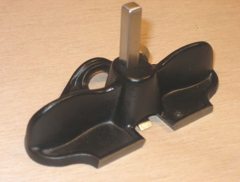
Figure 12 – Bullnose configuration.
Figure 12 shows that with the plane set in the bullnose configuration, the sole of the Lie-Nielsen 271 projects further than the tip of the blade. The Stanley 271, shown in bullnose configuration in Figure 2, is similar in this respect.
Maximum blade projection, with the top of the post set flush with the top of the blade clamp, is 27.5mm.
My impression of the Lie-Nielsen 271 is that it is a quality little tool. The components, all three of them (Fig. 7), look well made and are nicely finished. But how does it perform?
Function
The blade of the little Lie-Nielsen 271 was already quite sharp straight out of the box. Before putting it into action I polished the bottom of the blade (the sole of the foot) and honed the bevel on an 8000 grit Norton waterstone. This was a fairly quick and easy operation because the blade was quite well finished from the factory and its relatively small size meant that there was not much blade area that had to be worked on the stone.
My first test for the Lie-Nielsen 271 was to cut a recess for a 25mm brass butt hinge on the edge of a 12mm thick length of Tasmanian Oak. The timber sold in Australia as Tasmanian Oak is a hardwood that can be any of three similar eucalypt species. Early European timber workers called these species Tasmanian Oak because they believed that the timber was of a similar strength to English Oak.
I started by scribing the dimensions of the recess, using a wheel type marking gauge and a marking knife, onto the edge of the piece of Tassie Oak. The Lie-Nielsen 271 was then put into action removing the waste material to form the recess, working across rather than along the piece of Tassie Oak as shown in Figure 13.
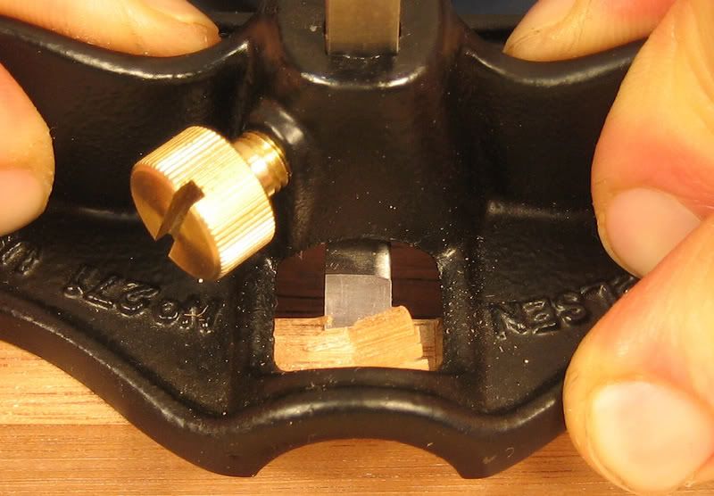
Figure 13 – Cutting the recess for a small butt hinge.
Balancing the little Lie-Nielsen router on the 12mm wide edge of the piece of wood did not present a problem. I completed the recess using three passes of the router plane, resetting the blade deeper after each pass until on the final pass the blade depth matched the thickness of one leaf of the hinges. I re-scribed the edges of the recess after each of the first two passes. With the plane sitting on a flat surface and a hinge leaf placed beneath the front and back as shown in Figure 14, setting the depth of cut for the final pass was a simple matter of releasing the blade clamping thumbscrew, lowering the tip of the blade onto the flat surface and re-clamping. Finger tightness was sufficient to hold the blade at the desired setting.

Figure 14 – Setting depth of cut for installation of butt hinges.
Surprisingly, to me at least, the open mouth configuration of the plane proved advantageous while cutting the recess. Figure 13 above shows the plane poised for the second cut of the first of three passes. The first cut, made adjacent to the knifed border of the recess, has raised a chip that is still attached on the side opposite the knifed line. The open mouth means that this chip, which would interfere with the passage of the second cut of a closed mouth plane, does not cause any interference at all. Prior to the third cut of the pass it was necessary for me to remove the raised chip because by this stage it had become too large to pass through the open mouth of the plane. After removing the chip, I simply pulled it off with my fingers, little raised dags were still present but these could pass though the open mouth without hindering the smooth passage of the plane.
The little router allowed me to complete a recess of accurate depth in a much more controlled manner than the chisel wielding methods I had previously employed. (Figs. 15 & 16)
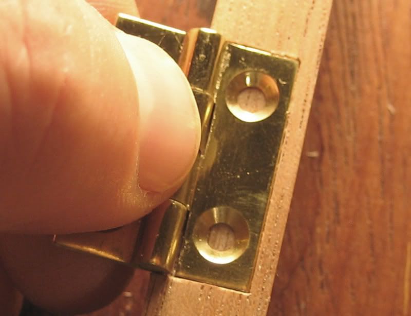
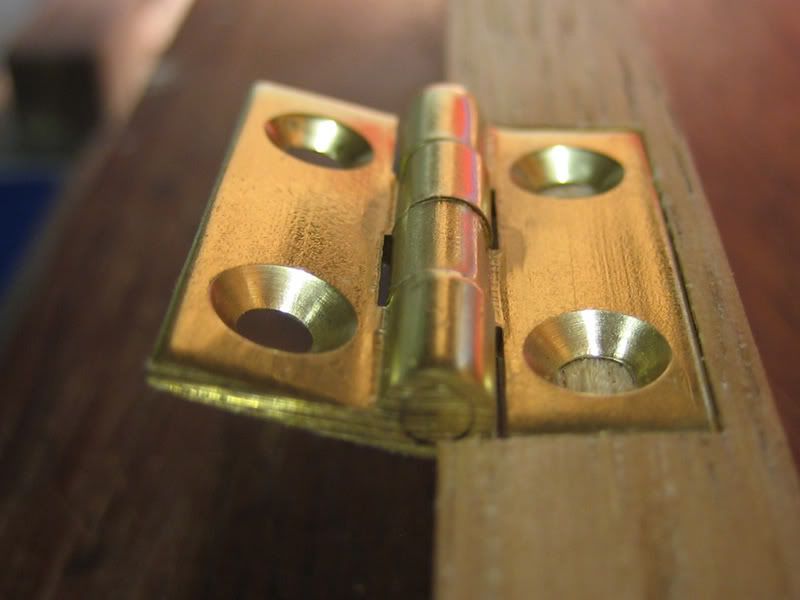
Figures 15 & 16 – Completed hinge recess.
Cleaning up the bottom of a shallow mortice, cut lengthwise into the edge of a piece of 19mm by 42mm radiata pine, was the next task to which I put the little router plane. A 3/8-inch mortice chisel was used to cut the mortice and then I used the plane to clean up the bottom. The mortice was approximately 8mm deep. This task highlighted what I think is one of the disadvantages of the open mouth configuration of the plane. You will recall that there is no sole area whatsoever along the centre line of the plane and that the width of this unsupported area is 18mm. The 19mm thick edge into which I had cut the mortice meant that there was virtually no support for the plane to do its job. Clamping a piece of scrap to either side of the piece being morticed (Fig. 17) was a quick way of getting around this problem but it obviously adds another process to the task which is not ideal. I would expect the design of the Stanley 271, with two small sole areas across its centre section (Fig. 10), and to a lesser extent the Record 722, which has one small area of support across the centre (Fig. 11), to be able to complete this task without having to clamp scrap in place to provide support. Note though that I haven’t used a Stanley 271 or a Record 722 so this is just supposition on my part.
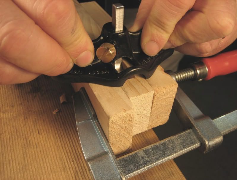
Figure 17 – Pieces of scrap clamped in place to provide support for the plane.
With the scrap clamped in place the plane was an effective tool for quickly cleaning up the bottom of the mortice.
The 19mm length of the ‘foot’ of the blade of the Lie-Nielsen 271 means that a mortice needs to be at least 38mm long if you want to be able to access the entire bottom of the mortice with the router plane. Inside a mortice less than 38mm long the back of the blade post contacting the end of the mortice will make it impossible to reach the middle of the mortice with the cutting tip of the blade.
I found that setting the plane blade was aided by the square blade post. The lateral orientation of the blade is fixed once the square blade post is inserted into its square hole and then depth of cut becomes the only consideration.
In use the slight “S” shape of the handles of the router plane provides a very comfortable grip when pushing the plane with the blade set in the normal position. The curve of the handles guided my thumbs to a position towards the centre of the plane and my fingers to a position closer to the edges (Fig. 18). This grip affords good control of the plane. Pushing the plane with the blade set in the bullnose position was not quite so comfortable and didn’t feel as natural. In this case the curvature of the handles produced a grip where the positions of my thumbs and fingers were reversed (Fig 19). I found that the most comfort and control was achieved by pushing the plane when the blade was set in the normal position and pulling the plane when the blade was set in the bullnose position.

Figure 18 – Grip for pushing the plane with the blade set in the normal position.

Figure 19 – Grip for pushing the plane with the blade set in the bullnose position.
In my opinion the single blade hole of the Lie-Nielsen 271 is an improvement over the Stanley 271. With the Lie-Nielsen you only have to loosen the thumbscrew to change the blade configuration from normal to bullnose. With the Stanley you have to remove the thumbscrew from one hole and re-install it another. Aside from being a pain, this presents the risk of dropping and losing the thumbscrew or if you’re a real klutz, cross threading it upon re-installation. The design of the Lie-Nielsen eliminates these problems without the more complicated drawbolt arrangement of the Record 722. While still having two blade holes like the Stanley 271, the Record 722 eliminates the need to remove and re-install the thumbscrew through the use of a single drawbolt that can grip the blade in either position (Fig. 20).

Figure 20 – Drawbolt for locking the blade of a Record 722. (Source: BugBear's Pages)
Conclusion
The Lie-Nielsen 271 is a quality little plane. It is solid and well finished. The open mouth configuration of the plane has its pros and cons but nothing that can’t be worked around. Other aspects of the plane’s design, namely the square blade post, the single blade hole and the shape of the handles, are in my view improvements over previous designs.
Lie-Nielsen Toolworks in Maine will sell you one of their small router planes for the sum of US$75. This price does not include postage, import duties or taxes should they apply. When you consider what some second hand tool dealers charge for vintage small router planes I think the price of the Lie-Nielsen is quite reasonable, of course you could pick up a vintage Stanley 271 or Record 722 for a lot less via eBay or at a flea market or car boot sale.
At the time of writing this review I could not find the small router on Axminster’s Lie-Nielsen website so I’m not sure what price will be charged in the UK.
Readers of this review will have to decide for themselves whether or not they think that the Lie-Nielsen 271 is worth the money. In my case I am confident that it will be a useful addition to my hand tool kit and will perform the tasks I had in mind for it when I placed my order.
References
Lie-Nielsen Toolworks Inc.
Lars Larson's Metal Router Plane Type Study
Patrick's Blood & Gore
BugBear's Pages
Fine Print
I have no affiliation whatsoever with Lie-Nielsen Toolworks Inc. I purchased the Lie-Nielsen 271 small router plane with my own funds. I am a bit of a fan of Lie-Nielsen hand tools, and own a few of their products, but I have tried not to let this cloud my judgement. I have tried to offer a fair and considered opinion of the plane. You can decide for yourself whether or not you think I’ve achieved this goal.