Improvement for my oval turnings

UKworkshop.co.uk

Help Support UKworkshop.co.uk:

This site may earn a commission from merchant affiliate links, including eBay, Amazon, and others.

Ad de Crom

Established Member
Joined
27 Nov 2009
Messages
333
Reaction score
0
Location
the Netherlands
Built in 2009 an oval turning device and turned since that time several objects, but had a slack in the constructed from wood and metal spindle.
Tried to make some reinforcements by placing steel rings for the roller bearings, this was a bit of an improvement, but not fully satisfying.
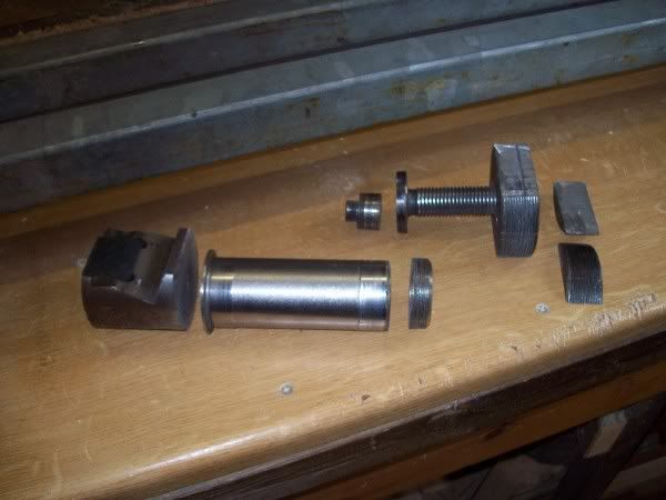
My wish was always a full metal spindle, and I stumbled unexpected against a metal spindle from an old machine in a junkyard and found more useful stuff. I got it for free, after a little talk.
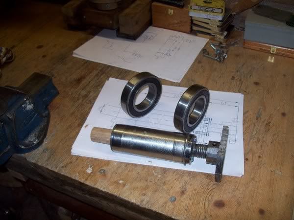
This is what I got my hands on, complete with two roller bearings of 50mm.
100_1967-metalspindlerollerbearingsandsomethingmore.jpg

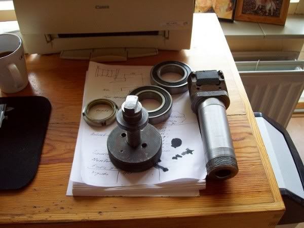
Now the job to transform it into a useful spindle, see piccy's.
100_1983.jpg

100_1989-spindlewithrollerbearings.jpg

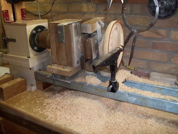
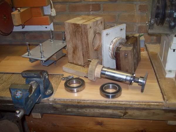
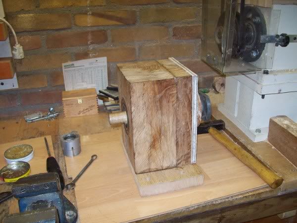
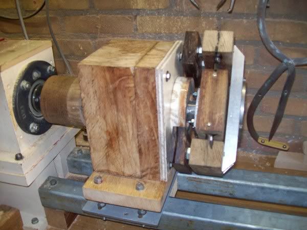
Had also to make a new housing for the spindle.
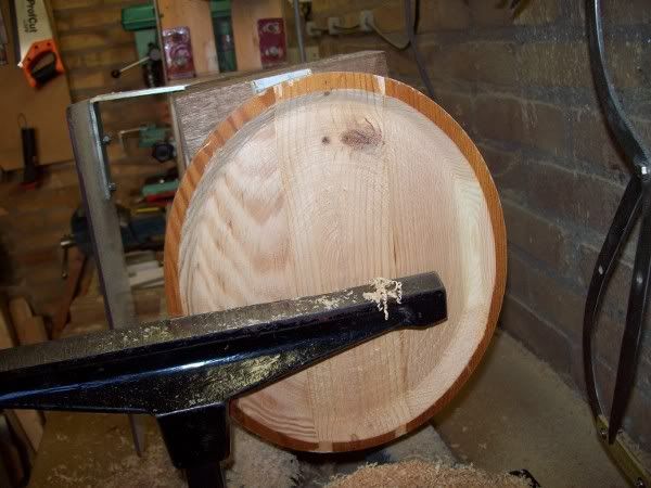
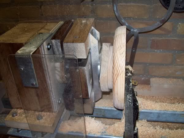
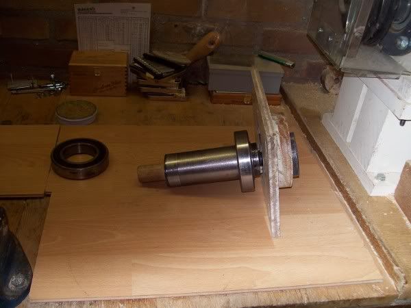
Assembled today everything, and did the first run without safety shield.
See the next pics, and video
100_1990-allparts.jpg

100_1991-assembling1.jpg

100_1992-assembling2.jpg

100_1993.jpg


Was a nice project for filling the gab while waiting for picking up my work on the staircase.
Tomorrow the first try out.
Cheers, and thanks for looking.
Ad
 
Wow, very impressive!

I've spent the last 5 minutes scratching my head trying to figure out how it works. Any chance you could explain the principles? Please?
 
ro":ikm0c99o said:
Wow, very impressive!

I've spent the last 5 minutes scratching my head trying to figure out how it works. Any chance you could explain the principles? Please?
In fact, steal the idea by watching the video from David Springett.
http://www.youtube.com/watch?v=LX12OFJHQlg
On this video he explain, better than I can :) , how it works.
Well the principles are very simple, a round cam set on an excentricity of the center, two bearers mounted on a slider (with two parrallel rods) and forced to follow the cam while rotating. On the fixing blocks of the bearers is mounted the faceplate. This all creates a perfect oval shape.
Something else than the complicated constructions of Bollinger, Steiner, or Volmer.
At least something you can build by your own.
Thanks for your interest.
Ad
 
Ad de Crom":1v0t5nb4 said:
ro":1v0t5nb4 said:
Wow, very impressive!

I've spent the last 5 minutes scratching my head trying to figure out how it works. Any chance you could explain the principles? Please?
In fact, steal the idea by watching the video from David Springett.
http://www.youtube.com/watch?v=LX12OFJHQlg
On this video he explain, better than I can :) , how it works.
Well the principles are very simple, a round cam set on an excentricity of the center, two bearers mounted on a slider (with two parrallel rods) and forced to follow the cam while rotating. On the fixing blocks of the bearers is mounted the faceplate. This all creates a perfect oval shape.
Something else than the complicated constructions of Bollinger, Steiner, or Volmer.
At least something you can build by your own.
Thanks for your interest.
Ad

Everything is simple when you know how Ad. I must admit it smacks of technicality to me which is another way of saying magic as far as I'm concerned. :oops:

Pete
 
Here some pictures of the first results after the improvement.
100_2000-firsttryoutafterimprovement.jpg

100_2001-firsttryoutafterimprovement.jpg

100_2002-firsttryoutafterimprovement.jpg

The steel spindle is the improvement, something I had expected.
Cheers, Ad
 
Back
Top