I blame Roy Underhill!

UKworkshop.co.uk

Help Support UKworkshop.co.uk:

This site may earn a commission from merchant affiliate links, including eBay, Amazon, and others.
Yes Richard that's exactly what I need. The old one was held on by a tapered pin which I have removed. It's still stuck tight but I have not yet tried heating or proper pulling with an extractor.
The other handles all have dimples showing that they were turned between centres.
I do have an ordinary electric lathe for wood turning and will resist attempts to push me down the DIY casting slope for now thanks!
 
Yes, I think you might have trouble making that handle without that handle.

Also, do you have a doming tool? Easy enough to buy off the rack for a Myford but I would imagine some adjustments would have to be made to fit yours ... bolted to something to hold in the vice ....?

You can dome to a certain extent by taking increasingly angled passes - on mine this means changing the angle of the small slide on top of the cross slide. Saw Roy do it with his, can yours do that? You can only go so far though, three passes maybe, as the cross slide will go no further over and I have been finishing off my domes by turning them with a file.

Much easier I should think to make a handle 'without the balls' in order to make one with. :) Maybe in mild steel, a piece of flat bar with a turned handle?
 
Hmm ... keep it up guys this is helpful. I think the first step is to get the old stub off the shaft and see how it fits. I could then make a rough replacement from flat bar (I have a bit about 8' long) with a bolt through one end holding a captive bit of copper tube. That should be stronger than wood and get me started. I am sort of hoping that I will be able to do curved cuts by swivelling the tool rest on its circular dovetail mounting. Not quite a proper ball turning jig but it might work. Otherwise I imagine a process a bit like trying to draw a circle on an etch-a-sketch, followed by quite a lot of filing.

How important is it to have this handle balanced by a ball on one side? Would a circular handle with a spinny knob on it be just as good?

I was about to post the above when Chipmunk's post popped up. That source looks brilliant!
I estimate my missing handle to have been a bit bigger - how much does that matter?
 
On mine, the cross slide ball handle is 3" long and the saddle moving wheel is 3 - 1/2" diameter.


Xy - I can't work out how big those handles you linked to are .... there are numbers but numbers of what?
 
Thanks again everyone we're getting there. From the bit left, I think my broken handle, which winds the carriage along, would have been about 4 inches/100mm long. Rxh, would you mind measuring the same handle on yours?

If that's the right size I think one of the WDS ones that you found Xy would be right. Assuming the fixing can be adapted somehow. So I will see if I can get it apart.
 
Sorry Richard, the page is not as clear as it should be. I am assuming the numbers are metric dimensions.
xy

P.S. I've just registered and downloaded the 2D CAD file. The dimensions are indeed in mm.
 
Andy,

I'll measure my handle at the weekend - I'm away in the far north of Scotland at the moment.
 
Andy,

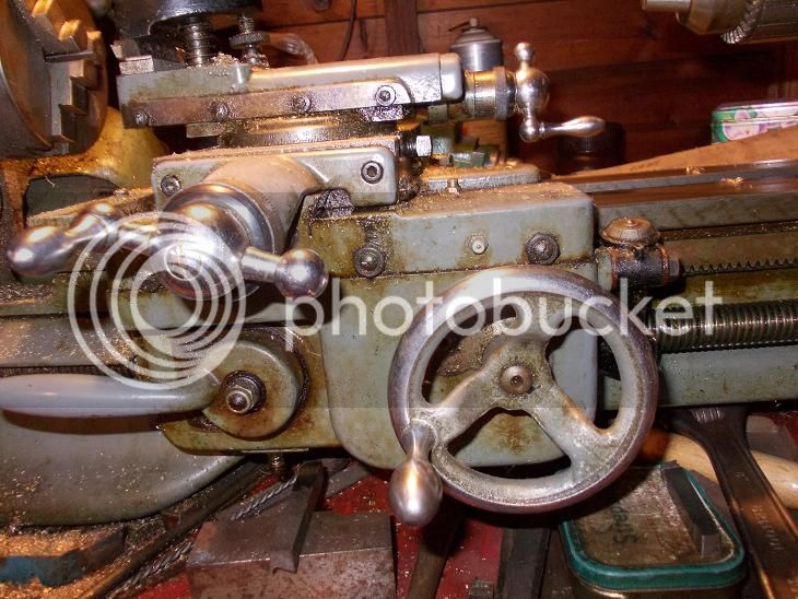
Here is a photo of my handle and a rough sketch. The dimensions should be legible if you click on the sketch to enlarge it.

I can't work out how it has been made or even how many separate parts there are. Maybe the parts were connected by shrink fitting?

I wonder how your handle suffered such brutal damage.
 

Attachments

  • IMG-07_08_13C.jpg
    IMG-07_08_13C.jpg
    245.2 KB · Views: 1,167
  • IMG_1127C.jpg
    IMG_1127C.jpg
    164.1 KB · Views: 1,167
RXH, that's brilliant!

Thank you so much for taking all that time and trouble, I really appreciate it.

I also know that my first project will be somewhat ambitious unless I can find a bigger spare part than those generously found for me already.

As for how it was made, my guess, judging from the dimples on the other handles, is that it was turned between centres but whether that was in two pieces or five I wouldn't know.

Lots more thinking to do as the cleaning continues...
 
Rxh wrote: Maybe the parts were connected by shrink fitting?


All the handle pieces on mine are solidly connected; there is no swiveling. Could be shrunk - fitted but I would guess that they are riveted in.
Not sure but that's what I would do if I were making one.
 
Time for a quick update. Not too exciting, but just in case I can encourage anyone else to do a similar job.

This week, I have mostly been cleaning.

Most of the parts were pretty filthy with a built up layer of old grease, oil and dirt. Fortunately this comes off quite easily with degreaser, hot water and white spirit.

IMG_2592_zpsaa175e58.jpg


IMG_2590_zpsd88c8297.jpg


The top layer can be scraped off with a stick:

IMG_2591_zpsdb869c2c.jpg


Then it's scrubbing time:

IMG_2595_zpsff292c22.jpg


IMG_2596_zps909d491f.jpg


The treadle is especially thickly coated:

IMG_2586_zps38c1eda4.jpg


Underneath the dirt there is little trace of the original paint. According to Roy Underhill, the original paint was decorated with coloured lines. I'm not going to attempt to recreate that. Instead, once the bigger bits are clean, I brushed on some boiled linseed oil, thinned down with turps. That's an idea that has been mentioned on here before in old machine restoration threads. I think it should give a surface that I can keep clean, without going back to bare metal and applying modern paint. After a few hours I wiped off the surplus with a rag (remembering to dispose of the rag safely - they can spontaneously ignite).

That gets it looking like this:

IMG_2605_zpsbece7247.jpg


Here's the flywheel before:
IMG_2527_zps57cf85a0.jpg


during
IMG_2603_zps14744f31.jpg


and after
IMG_2612_zps06fbeb8f.jpg


Doing all this at least makes me familiar with how the lathe goes together. In this shot you can see how a hard steel bearing for the shaft holding the flywheel is fitted into the right hand cast iron leg:

IMG_2594_zps0b78a445.jpg


That's a little wooden wedge that I'm holding. Nice and simple!

That's all for now, except to thank CC for his book recommendation - I now have a copy of "Using the Small Lathe" by Mason and it seems to be just what I need to get me started.
 
No actual metal turning yet but there has been some progress.

With most of the cleaning completed and the linseed oil dry over the remains of the old finish, the time has come to decide how to fit the lathe into the workshop. The only possible space is where I keep an assortment of bits of wood which will all be useful one day. Luckily I had recently tidied this area so it was quite easy to move a lot of cardboard boxes out into the corridor to await further reorganisation.

This is how it was before:

IMG_1609.jpg


My workshop is in the basement and the Victorian concrete floor undulates gently from side to side. I don't know if the builders were drunk or if they just thought it was good enough for the kitchen maid, but the lathe needs something pretty flat. Fortunately the offcut stock included most of a table top which is not only the right size but is painted gloss blue, which should repel oil drips nicely. It's wedged up level on some handy offcuts.

Here is the lathe starting to come together - I clamped the crankshaft to make sure it didn't all fall over. The back pivot bar for the treadle just sits in two holes in the feet.

IMG_2613_zps80fa67e1.jpg


With assistance from no 1 son, I lifted the bead and headstock into place and bolted the end stands onto it:

IMG_2615_zpsc79e05a3.jpg


The angle of that photo is a bit misleading - the wood is on wall brackets, not actually resting on the lathe itself. There is just enough space for now but I need to use some of it up!

The good news is that the flywheel revolves sweetly on its bearings and the treadle mechanism works just fine as well.

Next jobs include:

- fitting a new flat belt
- making a replacement for the broken carriage handle
- reassembling the slide rest and tail stock
- possibly getting the cracked change wheel welded

and then I'll start learning to turn metal!
 
Although I have use of a Myford Super 7 .... I am still jealous.

Biggest gear weld should not be of immediate importance ... I think you are going the exact right way. Get it seated properly and cutting properly. Your cleaning looks the biz.
 
A bit more progress towards my new indoor exercise regime...

I've tried (gently) to separate the broken handle from its post and gear wheel, without success. I removed a tapered pin but the two parts seem well united. I've not tried heat.

IMG_2602_zps660f0616.jpg


It will be a nice challenge to make a proper metal one, but to attempt that I need something that will make the lathe usable. So, admitting that it's the sort of temporary lash-up that might be used for a while, I have made a temporary handle from scrap aluminium and wood.

This is the sort of non-precision metalwork I feel comfortable with. I marked out a bar of thick ali and drilled a big hole in the middle for the existing ball to fit into. This needed to be opened out quite a bit. As luck would have it, one of the extra oddments with the lathe was a 7/8" drill bit, fitted with a cross-handle. (It's probably quite an old drill bit as it's marked with Morse's original 1863 patent!) I don't have anything to hold a bit that big, except the new lathe which I can't use yet, so there was no alternative except to do this bit by hand.

I was glad I'd chosen aluminium, not steel. It didn't take too long to get the hole to the right size. I don't recommend this technique, but it worked!

IMG_2626_zpsb7b503de.jpg


I then clamped the stub between more bits of aluminium and added a turned wooden handle, on a captive bolt. This left the handle unbalanced, so I added some lead washers to the light side.

IMG_2629_zps4adf997e.jpg


IMG_2627_zps9ae99d03.jpg


Definitely not pretty but it will work.

So, here's the lathe set up, nearly ready for the off:

IMG_2630_zps75840930.jpg


IMG_2631_zps319df8a2.jpg


IMG_2632_zpsf33eb354.jpg


One bit seems to be missing - a special bolt to hold an idler gear in place; luckily I had a suitable one for now - but I hope I can try making a matching one soon.

The belt should arrive this week, when I will find out if it's all been a waste of time. Stay tuned for the next installment!
 
Back
Top