How do I get Parallel sides to a disk?

UKworkshop.co.uk

Help Support UKworkshop.co.uk:

This site may earn a commission from merchant affiliate links, including eBay, Amazon, and others.

brianhabby

Established Member
Joined
24 Sep 2006
Messages
1,965
Reaction score
10
Location
Colwyn Bay, North Wales
In trying to prepare the blank for my Ship's Wheel Clock project, I have a 12 inch piece of timber mounted on the lathe. I am trying to get both sides perfectly parallel but it is proving to be a bit challenging.

Are there any tips that would help or is it, as I suspect, just a case of practice and experience? I don't want to make the piece too thin but the way I am going that just might happen :(

regards

Brian
 
Hi:
The method I use is showed in this video: http://www.youtube.com/watch?v=j5cF2libq-U
Basically, get one face as flat as you can using a gouge and checking with a straightedge, then us a flat board with sandpaper glued on to it for the final truing up. Once one face is flat and true to the lathe axis you can turn it around and repeat the process for the other face. If both surfaces are flat and at 90° to the lathe axis then they should also be parallel.

Good Luck!
Bob
 
Hi Brian,
Having watched the video Bob linked to, I'd have thought that light cuts with a narrow, 3/8" or 1/2", square ended scraper may be easier than a gouge working out the high spots until you get flat to your straight edge.

I'd then use something coarser than 120 grit as a starting point and then work through the grits as normal using the backing piece.

HTH
Jon


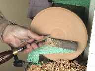
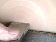
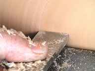
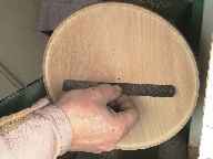
If you have difficulty in producing a flat surface try the method shown above, (pencil centre spot only for demonstration)
With flat ended scraper flatten central area so that scraper when positioned either side of centre is rubbing on surface, (this proves you are at right angles to the surface) then proceed to take small plunge cuts with the scraper until the scraper contacts the previously cut surface, working to the periphery, if you have kept the scraper square on then a steel rule placed on the surface should show no ridges or depressions.


The above images taken from A Cake Stand thread
 
+1 for flat scraper, a steel rule and light cuts.
The top plate for this months challenge has shown me how unflat what to my eye was a flat surface can be. So I used the flat scraper and then placed the rule over the surface, marked the high spots with a pencil, back to the scraper and repeat til flat. then reverse mount and do the same again.
Looking at your wheel design, it has a few things in common with the dreaded suspended ball item I made last month
file.php

what i did with that/ would do with your wheel and spokes, was, once the sides were parallel, on the front face marked the inner edge of the outer ring and the outer edge of the inner ring, cut half way in with a parting tool, sanded and draw the 'spokes'. then measured, reversed , marked and did the same on the back, leaving the final few mm till i'd finished sanding etc.
Then once parted off, sit the smaller disc inside the large one, line up the drawn spoke lines clamp together and drill pilots on the bench drill. then line up the next spoke etc etc.
It will help if your fixings to the faceplate line up with the timber you dont want i.e. the gap between the inner and outer rings. you can use a bit of scrap wood and 4 more screws to do this if needs be.
 
Some very useful tips there people, thanks very much.

Nev, if my project looks half as good as your I'll be happy.

I'll try again but it is not getting the sides flat that seems to be the problem, more getting the two flat sides perfectly parallel. I guess it's a case of making sure the sides are perfectly square to the edge.

I'll have another go this morning.

regards

Brian
 
brianhabby":hc1wpe2v said:
Some very useful tips there people, thanks very much.

Nev, if my project looks half as good as your I'll be happy.

I'll try again but it is not getting the sides flat that seems to be the problem, more getting the two flat sides perfectly parallel. I guess it's a case of making sure the sides are perfectly square to the edge.

I'll have another go this morning.

regards

Brian

If you use a 12" rule across the whole face/ faces ( as opposed to across the half you turn) it has no choice but to be parallel , Ithink :?
 
Thanks, although I wasn't referring to the two halves of the same side, I mean the two opposite sides of the disk.

I've had another bash at it this morning and although it isn't 100% perfect it's as close as I think I'm going to get it. I have decided to leave it as it is because I don't think it will be so critical on the finished piece and in any case if I keep trying I'll finish up with a very thin disk or make it worse than it is (or both).

regards

Brian
 
brianhabby":qryiuqwp said:
Thanks, although I wasn't referring to the two halves of the same side, I mean the two opposite sides of the disk....
regards

Brian

So did I :oops: If its flat across the one face, it has to be 90# to the spindle, then you flip it and do the same, that side will be 90# too. so they should be parallel. anyhow... glad you got it sorted :)
next up, to drill or not to drill. :shock:
good luck.
 
If the two sides aren't parallel, the error has to be in how the workpiece is mounted for turning the second side. Check your chuck spigot or recess is as close as possible to the optimum size (and angle) for the jaws you are using and make sure the register face (which ever bit is mating against the chuck or jaw face) is cut clean and true with no radius on the internal corner of the spigot that might prevent the jaws locating all the way in.

It might also be worth checking the jaws are all aligned by closing them together.
 
Thanks for your very enlightened observations Paul. I was beginning to think along similar lines but was really unsure.

When I first mounted the piece I used a faceplate with my Record chuck which is fastened with four screws, a very positive, I think, fixing. To mount the other side I used a Nova chuck that has dovetail jaws which clamp as they open.

I cut the dovetail using a dovetail scraper so am fairly confident that the angle of the dovetail is as good as I can get. However, I am beginning to think that this rebate for the Nova chuck is too deep. How critical is the depth of the rebate for the dovetail jaws? I am thinking that the jaws should bottom out, which would help make sure it is mounted square. As it is deeper than the dovetails I think it has not been mounted perfectly square.

Not sure if I've made myself clear - hope so.

regards

Brian
 
If you make the dovetail recess deeper than the depth of the dovetails on the jaws, the outer rim of the jaws will become your mating face and as that area is wider than the faces of the dovetails (which would be used if the recess was shallower than the jaws), the odds of your blank running true are improved.

Another way to improve the situation is to use a larger diameter set of jaws.

However, some sets of dovetail jaws have very deep dovetails so in that case, I would make the recess shorter than the jaws, subject to the provisos about optimum angle and size. I don't think I explained the optimum size bit in my previous attempt - what I mean is that the jaws will only prescribe a full circle at one point on their range from minimum to maximum opening. At that point, if they are mating with a circular spigot or recess that corresponds to that size then the jaw contact will be as good as you can get. If the spigot is too small, the jaws only contact in the centre and if the spigot is too big, the jaws will only contact on the ends. For a recess it's the other way round but the same applies - match the jaws to what they are gripping. Most jaws are at their optimum when they are opened so there is a gap of around 6mm between them.

When I make clocks I just cut the centre out and mount the remaining ring on a set of button jaws which grip the inside of the hole. That way the mating surface is virtually as big as the blank I'm turning.
 
Back
Top