Horizontal workholding on the WoodRat

UKworkshop.co.uk

Help Support UKworkshop.co.uk:

This site may earn a commission from merchant affiliate links, including eBay, Amazon, and others.
A

Anonymous

Guest
Hi all

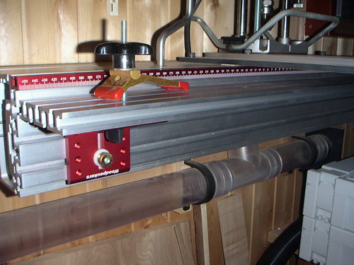
One of the main issues I have always felt needed addressing with the WoodRat was the lack of horizontal work holding.
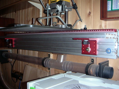
I also never really saw the need for two clamps and felt that this was an issue as I often wanted to clamp wide pieces but couldn't use the whole length of the machine. I moved the centee, fixed clamp, down near the left end of the machine to allow more clamping room, and decided to make an easily attachable horizontal workholder (I made 2 very different designs, but only one shown here)

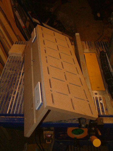
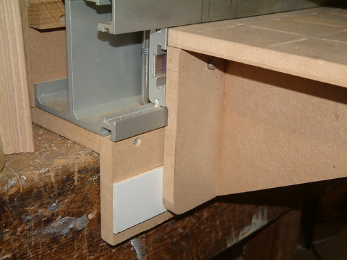
This prototype work holding arrangement is from 19mm MDF. Took around 1 1/2 hours to make, and is attached using four 8mm bolts which screw into tapped holes in the slide.
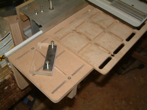
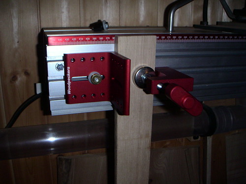
I cut T slots along the top to capture M6 bolts which allows flexibility when mounting workpieces. The first bracket works well and is simply a piece of angle iron with M8 thread for the camp to run through.

Works much better than I even hoped and I will be making an aluminium version soon with a few modifications to improve it's versatility.

Takes 2 minutes to remove completely, and the hieght of the table is adjustable.

some piccies:

In_position-medium.JPG


T_slots-medium.JPG


Underside-medium.JPG


And a milled test piece

Cut_finished-medium.JPG
 
Looks good, Tony! I copied Alf's design (on Aldel's website) which has a tendency to droop a bit. Added extra fixings make it some what like yours - I find big ply T nuts that slide in the cam clamp channel a useful way of adding security to all sorts of jigs. Slide out r/h cam clamp, slide in T nut/s and replace clamp; cam in jig/gently tighten fixing screws into ply T nut to remove any unwanted play.

Very envious of your T slots and aluminium intentions!

PS. Would tufnol (routable T slots) do instead of ali, strengthwise? I ask as it could be fixed to an inverted mortice rail
 
Tony

That's exatctly the same limitation I've found with the rat. Nice solution indeed, I think that someone else has documented a similar table (Alf ??) somewhere on the net. I hope you don't mind me nicking this design for my rat.

How did you mill the T slots? Do you have a dedicated cutter, or is there another way? Were they cut on the Rat, or on a router table?

Please keep us posted with the Alu table.

Thanks

Aled

P.S. Sorry about the ream of questions, but It's a solution I've been looking a long time for.
 
Ivan

We must have been typing at the same time - yes it must have been Alf's table, as we both referred to it.

Great minds think alike eh?

(or do fools seldom differ?)

Aled
 
Hello Tony,

I have also been working on a totally new approach to work holding for my rat. I will post some pics tomorrow.

A study of the Router Boss gave me a few ideas, it is not all that different from your approach, but in aluminium using T track and some woodpecker accessories.

I still have a few issues to resolve but I am initially excited by the advantages.

Glad to see that I am not the only person who has spent hours fiddling with their rat. :)

Cheers, Tony.
 
What an inspiration. How much does the MDF version weigh?

My friend has the new MR3 Alu mortise rail, and the weight of it is a big issue.
I bought the WR 2 years ago and put off making a Mortise Rail for ages. I am really inspired to dive into making the Horizontal Table. What material .... I just don't know.

But I will incorporate the L/R (east/west) digital scale onto it. The scale currently replaces the fixed cam clamp, since you don't need anything in the Marker Position.

Tony, I hope your invention breathes new life into the WoodRat community.

Gary Curtis
Northern California :D
 
74extiger":2gifzwy2 said:
.........
My friend has the new MR3 Alu mortise rail, and the weight of it is a big issue.
.......
Tony, I hope your invention breathes new life into the WoodRat community.

Gary Curtis
Northern California :D

Weight an issue? Not really!

P1050565.JPG


Nice work, Tony, by the way :D
 
ivan":harpcrr2 said:
I find big ply T nuts that slide in the cam clamp channel a useful way of adding security to all sorts of jigs. Slide out r/h cam clamp, slide in T nut/s and replace clamp; cam in jig/gently tighten fixing screws into ply T nut to remove any unwanted play.

Very envious of your T slots and aluminium intentions!

PS. Would tufnol (routable T slots) do instead of ali, strengthwise? I ask as it could be fixed to an inverted mortice rail

Thanks Ivan :D Any chance of a photo of your T nuts? sounds interesting.

The aluminium is a problem at the moment as I CADed it up and checked the mass (weight) which is 3kg for the top alone!!!! :roll: for the same design. So, I am working on an open frame design at present. (down to 2KG).

Tufnol might be a good solution. At the mo, the MDF is working surprisingly well, so I might make a composite version with ali fixings and some other material for the top. One thing I will avoid is the mortise rail approach as that was really the thing that got me thinking that the horizontal workholding was very poor.
 
74extiger":23nuirp8 said:
What an inspiration. How much does the MDF version weigh?

Thanks Gary

According to my 3D CAD model, the top has a mass of 1.355Kg (taking MDF density as 700Kg/m^3)

Rear is 1.557 Kg (much material can be removed from this without compromising strength though)

Each triangular support 0.187 kg

The same structure in aluminium (same dimensions all round) has mass of:

Top 5.251 kg

Rear 6.031 kg

Bracket 0.724 kg

However, with my new design, the aluminium version will have a lower mass than the MDF one - brackets and rear considerably lower. Will post estimates a little later
 
Aled Dafis":348e3fzk said:
Tony

That's exatctly the same limitation I've found with the rat. Nice solution indeed, I think that someone else has documented a similar table (Alf ??) somewhere on the net. I hope you don't mind me nicking this design for my rat.

How did you mill the T slots? Do you have a dedicated cutter, or is there another way? Were they cut on the Rat, or on a router table?
.

Hi Aled

Not seen Alf's, so must search her site for a quick look

T slots were cut on the router table using a Trend keyhole bit that cost a lot less than £10 several years ago
 
The jig-maker in you is back! Looks good - at a cost, one of the extrusion systems (like the bosch rexroth, or the festool one (MFS?) someone posted about the other day) might be a solution to the weight issue? They come with t-track slots, too. There must be connectors which would allow you build it up width-wise, if the basic extrusions are too narrow - certainly with the bosch stuff, I'd imagine.
 
Tony, two things seem possible to me. The top surface can be thin since it doesn't need to bear much weight or pressure. Perhaps a honeycomb wafer as is used in aircraft flooring and interior bulkheads.

And the under-carriage support material could be designed much like a spaceframe or bridge. You know, made up of many small members in tension or torsion, possibly with cables.

Gary Curtis
 
This is how I got round it, seems pretty similar...
2502142653_65acb20d9e.jpg

It's made from 18mm MDF and the top is replaceable as it's held in place by screws, the theory being it will get cut into at some point, though it has not happened yet. It attaches to the sliding rail with cleats that are made of acrylic scraps screwed together, one at each end, the screw in the middle goes into the tapped hole in the centre of the lower rail to stop it moving relative to the rail itself.
2502144247_22297f651a.jpg

To stop the table tilting down I have fixed on some acrylic below the machine to the same thickness as the machine sits forward of the mounting, such that the table bottom runs against it stopping it from leaning forwards, this has worked rather well.
2502974396_f06aaaa923.jpg

I use tapped blocks of acrylic with self-adhesive sandpaper to hold the work on the table, some stainless plate makes big washers for the underside of the table. Also shown here is the template made from 6mm ply, with this I can cut a new table using a guide bush and 6mm cutter from MDF in about twenty minutes

Aidan
 
Good evening fellas,

As promised here are few pics of my efforts regarding this matter, still very much a work in progress, but it seems as though it will work very well.

2503174288_6fe7655f82.jpg


As you can see I have bolted a piece of super T track to the front of the rat. The red story stick needs to be cut and attached to the T track, to reveal the hole which the cutter passes through. I plan to cut this so the zero measurement is at the point of the cutter.

The T track on the top of the story stick will be useful for attaching a stop when necessary. I haven't yet figured how to use my pencil on this for east / west work. My initial thoughts are to make an insert for this purpose.

Here is another pic

2502347607_7b47793705.jpg


I can raise or lower the shelf which is attached using the woodpecker bracket. I can also hold pieces on the shelf using the hold downs as shown.

The shelf simply slides out when needed and by turning the bracket 90 degrees I can make a more familiar set-up, as follows;

2503179464_9f009c7a68.jpg


I have not weighed the T track but I do not appear to be suffering from significant droop. ( :wink: )

One issue I did encounter when attaching the T track was if tightened too much the winding mechanism did not work. I eventually arrived at an acceptable balance on this issue and it works fine. I may put some slippery stuff on the inside to help.

I need to do a bit more work on this project, but fancy it will be a long term work in progress, such is the nature of this machine.

Hope this is of further interest.

Cheers, Tony.
 
Yes inded, Escudo! Super T track? Not sure where to find that?

Tony, re big T nuts, nowhere handy to post pix. I just used some ply scrap, and put rebates on opposite sides, so it will slide along as per cam clamps. Approximately square with a central hole, has a pronged T nut insert pressed in the back providing the f thread.

Not entirely original, I was prompted down this road by Aldel's site (or a Woodrat.com link) to someone who had removed the standard fences/clamps and covered the whole front with a vertical face fitteed with T track - he fitted various holding devices to the tracks as required. This vertical new face was held on by a long mild steel "Tnut" tightened just enough to remove the rattle.
 
Ivan, Super T Track is made and sold by these two American wood supply dealers:

www.a different place.com (they refer to theirs as Ultra Track

www.woodpeck.com

Woodpeck and a different place also make those angle brackets and story stick contraptions.

It isn't very costly. If you want to save on shipping and can wait 6 weeks, have it sent by surface mail.
 
74extiger":1nummr85 said:
Tony, two things seem possible to me. The top surface can be thin since it doesn't need to bear much weight or pressure. Perhaps a honeycomb wafer as is used in aircraft flooring and interior bulkheads.

And the under-carriage support material could be designed much like a spaceframe or bridge. You know, made up of many small members in tension or torsion, possibly with cables.

Gary Curtis

Hi Gary

Pretty much what i am drawing up for the aluminium version. The rear might even be two thin vertial sections and the top surface only needs depth where the T slots are located. I am thinking of a composite structure for the top. The supports can be open triangle sections in ali.


I can post 2D CAD if anyone wants the drawings for the jig I have already posted?
 
Hi Tony,

Great work on the horiz. table. Have you checked for square? If so, can you tell me how the to ali pieces relate to ea other and also, how the horiz piece relates to the face & top of the 'rat? Thanks very much!
 
Back
Top