A tale of three parts

UKworkshop.co.uk

Help Support UKworkshop.co.uk:

This site may earn a commission from merchant affiliate links, including eBay, Amazon, and others.

adzeman

Established Member
Joined
5 Jul 2008
Messages
513
Reaction score
0
Location
East Sussex
This is a WIP of three parts running concurrently.

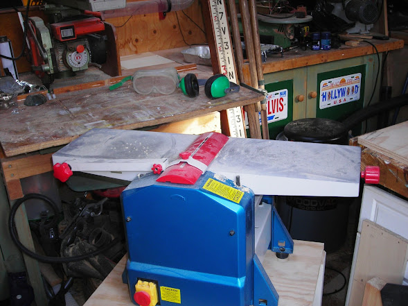
Firstly. In September last year purchased a thicknesser/planer where does it go in a small crowded workshop?

Second It requires a stand.

Third. I need to improve my door making skills.

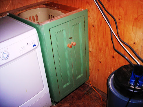
Part of my negotiations with SWMBO I agreed for our dryer and spare washing machine to be kept in the workshop along with my beer fridge. as luck would have it some of our white goods went belly up and a visit to the fire sale at Comet resulted in all our kitchen white goods being replaced. This resulted in a re-negotiation with floor space resulting in just the dryer staying along with my fridge.

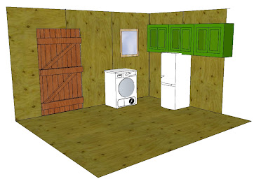
So this is the canvas.
thicknesser%2Bbase.jpg


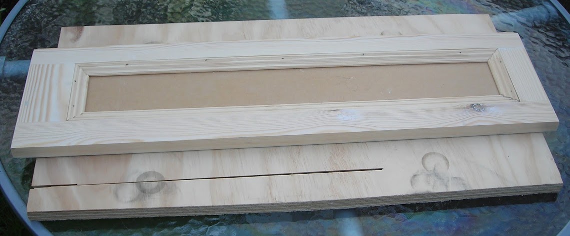
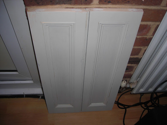
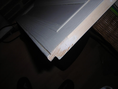
Further to the three parts I need to improve my skill set in making doors. I am happy making them out of timber wether hardwood or softwood but I would like to tru other materials such as MDF and some of the modern paints which most kitchen units are decorated.
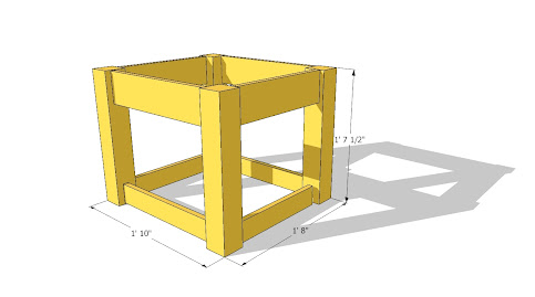
So this is the plan

The%2BPlan%2BJPG.jpg


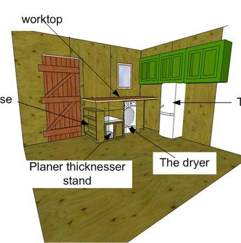
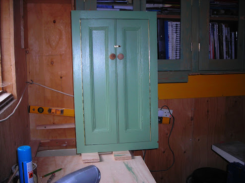
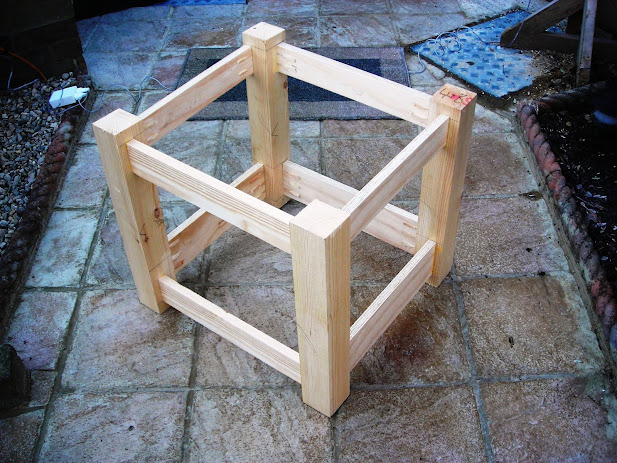
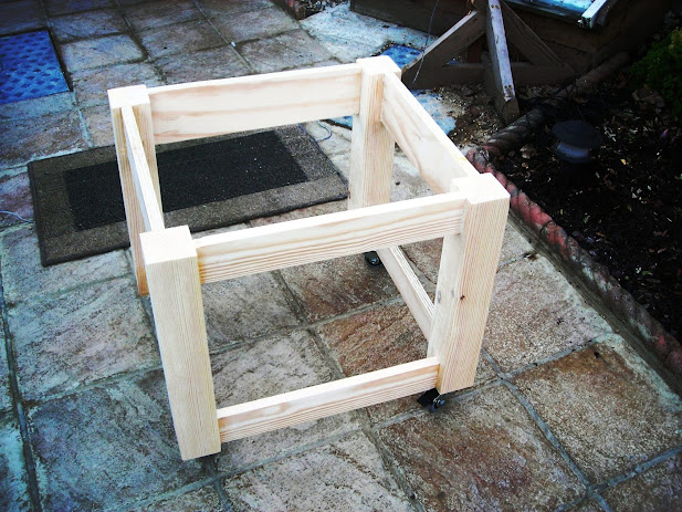
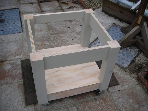
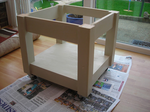
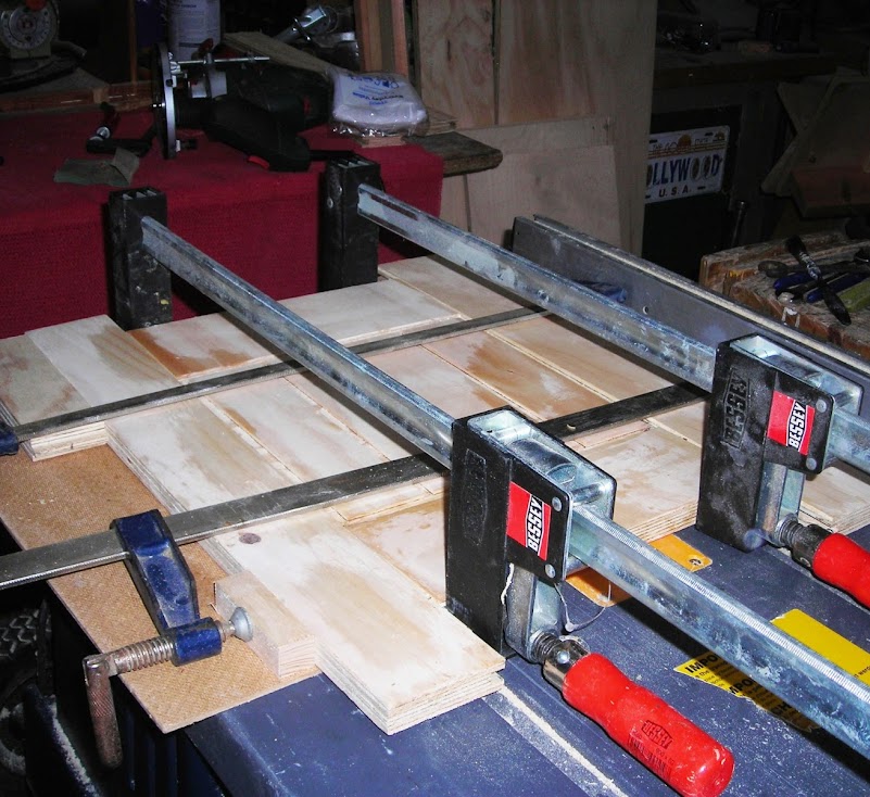
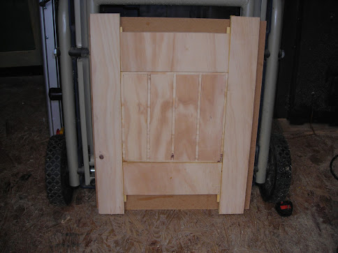
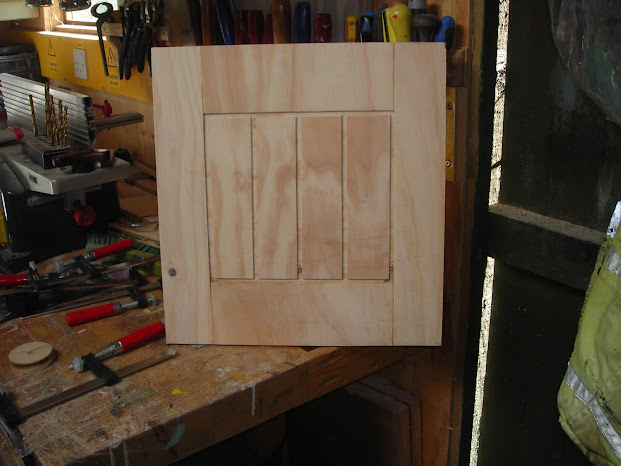
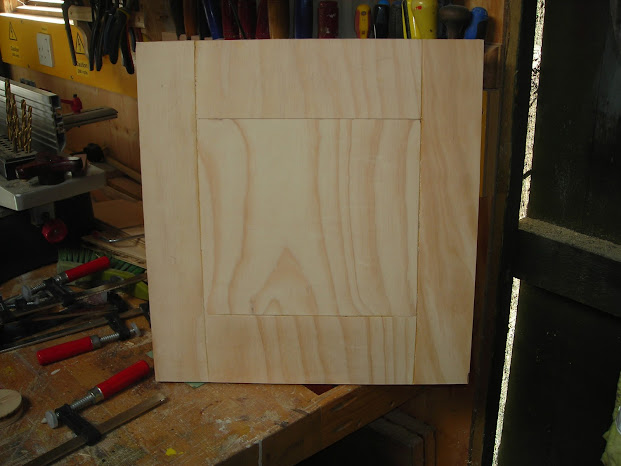
There’s a lot to work out from this plan so the first item is to build the first cupboard keeping it as small or narrow as possible. The minimum width being the width of the wash basket it has to hold.

End%2Bcheek%2Bof%2Bdryer%2Bcupboard.JPG


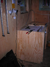
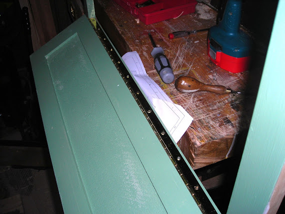
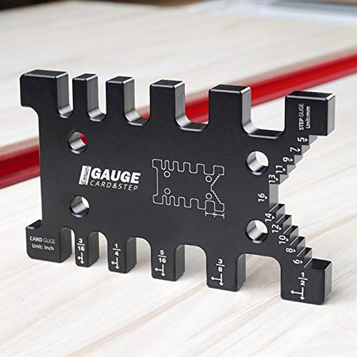
Having established this position the next point will be the tool stand/shelves or is it the planer/thicknesser base? I need both, I have the dimensions of the planer but it has a number of protrusions, knobs and the like and it may have to spin to come out of the gap so the planer base is favourite. I used the top rail of the cupboard as a rod to calculate the height as I want the planer plate to be just 6mm above my bench heights.

The+rod+for+the+planer+base.JPG


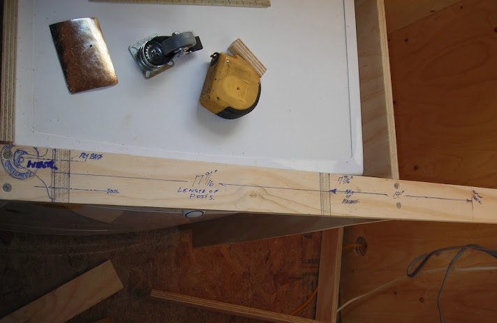
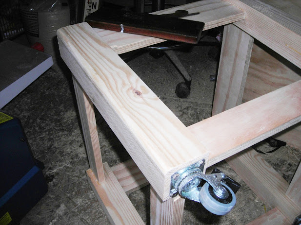
I purchased the casters and used them to calculate the height off the floor.
 
My basic thoughts put on to Sketchup.

Machine%2Bbase%2Bframe.jpg


Depending on the Rugby this aft will cut out the stock using the rod. I find these days cant do the simplist job without one make too many masuring errors. What an admission for a surveyor. Could be an age thing, Have to wear reading glasses too many other distractions.
 
Part three was the making of the doors and trying out the new matt water based paints that have become popular especially with the new legislation coming into force banning oil based paints. I started the door process some two weeks ago eager to try out theF & B paints I had purchased.
I started by making a 2 x 1 softwood face frame.

Making%2Ba%2Bface%2Bframe%2B.JPG


The rails and stiles were given a central groove

Ploughing%2Bout%2Bthe%2Bcentre%2Bgroove.JPG


It was then when I realised is was not a tale of three parts but a tale of four parts. Using a plough on plywood or MDF will not work I will have to start and complete that project I have been putting off for a few years now that is make a router table with a router lift.

A completed basic door with planted mouldings. I would have preferred a bolection mould but as I finished this door last Sunday and was the only mould available from Homebase. When the router table is working forming a bolection mould could be another oroject.

A%2Bcompleted%2Bdoor%2B-%2BCopy.JPG


The pair of doors undercoated.

The%2Bfirst%2Bpair%2Bof%2Bdoors..JPG


Here is an error in workmanship. despite trying out on scrap wood a drop in concentration caused a slip and a rescue was in order and yhis was the best I could give. I did manage to sand the whispy fibres away. I should have formed the staff bead prior to assembly then I would have only ruined a style which then would be replaceable now I have a below standard door. Most people dont notice the defect but every time I look at the door my eyes go straight to it.

DSCN4986.JPG


Hanging doors to face frame.

Hinges%2Bscrewd%2Bon..JPG


Hung doors on face frame with door knobs and turn button

DSCN4996.JPG


Completed cupboard

Face%2Bframe%2Bfixed%2Bto%2Bcupboard.JPG


I know some of you have used F & B paints and not been happy with the results but I am quite satisfied with the results so far.
Must start on planning out how to build a router lift on a router table.
 
Can I just add if your keeping the dryer in the workshop try to make the unit around it as tight from dust as you can. I trashed a dryer that used to be in my workshop and it was wood dust that got taken into the air intakes and eventually cooked it.

just a thought
 
I see you use a storey or setting out rod and a good example to us all especially when you get tired. There was a thread about this a while back. Excellent for consistent sizing. To some extent they went into decline after everyone could read and write. I know we have rather gone backwards there so we may see them coming back! Presumably the foreman did the rod and it was passed around at each stage. Also when repitition was needed ..same door, same windows, that sort of thing. Now did they cut to the pencil line or over the line? Must have been in the marking..need to think. Best wishes.
 
two thumbs wrote
Presumably the foreman did the rod and it was passed around at each stage.
Our shop was a small village shop and we were all taught the essential use of a rod. We used a 2H Pencil with a chisel point to mark out. This gave a fine line and was constantly sharpened on a scrap of fine sandpaper. When I left the the village shop to train as a surveyor the large joiners shop had a setting out department which had long benches. For the very large projects say shopfitting they used rolls of detail paper (similar to tracing paper) same stuff we used in the drawing office for other work they had long whitewashed pine boards. With regards to which side of the line it was a thin line and as long as you were consistant and marked only one way say left of or right of line or centre of line it didnt matter. One important point you cannot set a machine exactly the same so once the machinist had set his machine he protected it untill all stock had been cut. If the machine had to be left over night he took the fuse home with him.
I am not sure what practices (change to) I do not know what practices are in place today all I know then measurering was kCarpenters would come back from site with a strip of wood where the actual size was marked on it saay of the width and height of an opening. If you go to York Minster they have a medeval setting out floor in clay and they wood mark out the windows and doors full size and use this for making windows and doors including the tracery of stonework.
 
Progress for today.

Framed together

Glued+and+assembled.JPG


Corners rounded off using my 18th centuary plane

Rounding+off+the+corners.JPG


Horns cut off and sanded down and and castors

Cleaned+up%2C+sanded+and+castors+added.JPG


Floor added

wood+planes+005.JPG


First undercoat for mid tones (Need undercoat for deep tones)


wood+planes+006.JPG
 
Part four the router lift.

Securing the router to a 12mm ply backing.

DSCN4976.JPG


Cleaning rebates after bulk of waste removed with the table saw.

Forming%2Bthe%2Brebates.JPG


Sliders in position

DSCN5001.JPG
 
Cock ups three
The width of the doors to the cupboard for the basket are a shade narrow opings OK but doors do not fold back enough so will have to buy her a new basket.

If you look at the jubilee clips I cant get access to take the router out so I need new clips and bend them the other way.

The width of the ply needed to be wider by 12mm to give more room for the holding bolt and the threaded rod.

I really ned a router lift to make the router lift (homer)
 
Thanks Pete it was not the actual process of screwing the bolt when I put the other plate in the sliders it was directly over the screws I have turned them round noe and all is working except the screw handle I made the bolt has fallen out :roll: I will do another embarrising pic.
 
Bolts face wrong way

DSCN4976.JPG


Close up showing bolts facing wrong way Cant unscrew them

Enlarged%2Bto%2Bshow%2Bbolts.JPG


Making the turn screw

DSCN5003.JPG


Nut Araldited in

DSCN5004.JPG


Cut out Turnbutton

C%2Bsaw%2Bout%2Bshape.JPG


Cutting out completed

D%2BThe%2Bshape%2Bcut.JPG


Turn buiion added to shank and varnished

DSCN5007.JPG


Top routed out and ply infill added with completed turnbutton

DSCN5012.JPG


Dissaster showing the nut became unstuck fron shank

OOPS%2521%2Bthe%2Bnut%2Bfell%2Bout.JPG
 
Wth the undercoat dry I can now check the height against a work bench. Its fine the planned 6mmm

Checking%2Bfor%2Bheight.JPG


The doors can now be made using my new router lift (using a spanner till I repair the turnbutton)
The first door from the Homebase catalogue I will call the Lacsells (their may be a copy right issue here?)

The glue up

Lascells%2Bglued%2Bup%2B%2B%25282%2529.JPG


Cramps removed

Lascells%2Bwith%2Bcramps%2Bremoves.JPG


Sanded and trimmed to size. Face

Face+of+the+Lacelles.JPG


Ditto inside face

Back+face+of+the+Lacelles.JPG
 
Hi, Mike

Try a putting a T-nut between the laminations, that should stop the problem with the nut pulling out.

Pete
 
Thanks Pete that was one of the ideas but would mean making a new turnbutton thats do big deal. Another idea is to screw a large washer over the top of the nut. It has been working OK with the spanner without the turnbutton just a bit fussey.
I need to move on with the project and complete the stand. Because of tight space I need to work out the slight turning of the table as I pull it out and see what protrusions get in the way.
 
Hi, Mike

You could use the existing top and make a new bottom piece, the ply should split one on the laminations.

Pete
 
Very true Pete I am being pressurised at the moment by the wife to get this saga finished and I am begining to feel I have started a job too far. While this work is going on the shops all over the place. Knocked out another door this afternoon which I am calling the Shoreham. Still took some grief though.

Router Table set up for use

The%2BRouter%2Btable.JPG


Routering the grooves.

Router%2Btable%2Bin%2Buse.JPG


Set out for a glue up

Ready+for+glue+up.JPG
 

Latest posts

Back
Top