Reversing a 3ph motor.

UKworkshop.co.uk

Help Support UKworkshop.co.uk:

This site may earn a commission from merchant affiliate links, including eBay, Amazon, and others.

harris

Member
Joined
19 Jan 2012
Messages
16
Reaction score
0
Location
shropshire
A question for Bob but anyone else with the relevant knowledge please chip in. The LENZE inverter that I am bidding on doesn't have a motor reversing facility as far as I can gather from their web site. It is very handy to be able to "run Backwards" when wood turning/sanding so I'm keen to achieve that option. I understand that by changing over any two of the three motor connections will achieve this. Is there a switch that I can incorporate in the cable between the inverter and the motor that will change two of the cores over and if so what type/sort of switch is it called when I buy one from an electrical wholesaler? That is assuming I put in the winning bid and get the inverter.
Fred.
 
Yes, changing over any two feeds to the motor will change the direction.

But a better and safer option is to use the low voltage switch inputs on the invertor, I would be very surprised if the invertor you are purchasing did not have them.
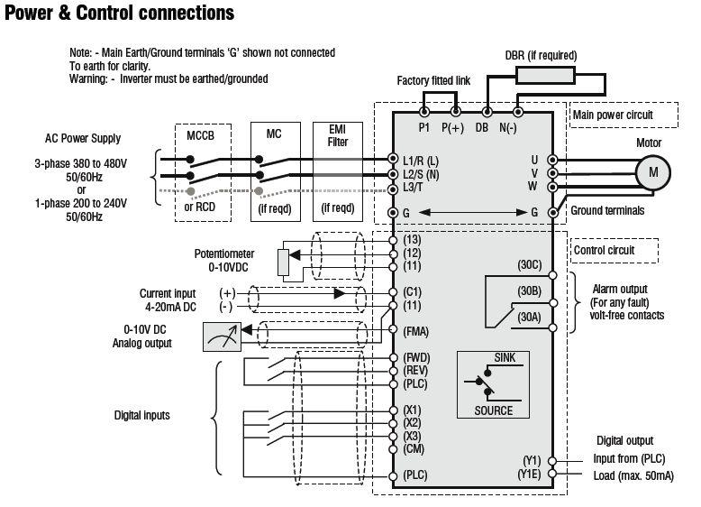
This is a typical invertor wiring diagram (Jaguar). (see digital inputs)
Jaguar.jpg


Typical LENZE inverter shows a reverse facility.
 

Attachments

  • Jaguar.jpg
    Jaguar.jpg
    75.9 KB
I havent seen any inverters that dont have a reversing input but thats not to say that the lenze wont (I'm not familiar with lenze)
Its not recommended to put any switch between the output of an inverter and the motor but you just need an industrial switch with 2 changeovers on it
and then just make sure that you never operate the switch whilst motor is on
 
I must admit that in all my years of playing with inverters, I've not used one that has not got an inbuilt reversing capability but then again, I've not used a Lenze.

The golden rule of preserving inverter life in my book is never to have any switching between the inverter and the motor as momentary disconnection of any phase can lead to voltage spikes.
To be honest this would put me off the lenze inverter - there are loads more out there.

Anyway , the switch you want is a 2 pole changeover break before make. There are simple toggle ones or rotary ones but make sure the contacts are rated for mains voltage and inductive loads.
Then you will have to get used to the sequence or stopping the motor, switching off the inverter, changing direction, turn on the inverter and finally restart the motor to make sure you don't kill the inverter.
Faced with this - I would go for a different inverter but - up to you.
What is the power requirements of your motor?

Bob
 
Thank you for all those contributions, what a great forum this is. I will look out for those connections mentioned and now that I have won the bidding, the inverter should be with me in a week or so. The motor is a 1HP job by the way. I did try to phone LENZE in the UK but once it was established that I only wanted to make an query and not buy anything the receptionist went "all frosty" on me. Maybe I can try again and try to buy a hand book for it. If I don't get anywhere I will come back to the site and pose more questions.
Fred.
 
I'm back again after zooming in on the Jaguar drawing and finding the digital input and the Fwd and Rev notations. However, not being too clever on electrics and having no knowledge of electronics I don't really understand what a digital input is or where a low voltage supply would come from - perhaps internally from the inverter? Connected to the faulty inverter that I am replacing and mounted on the lathe head stock there is a small plastic sealed housing that contains a 3 position rocker switch and a potentiometer. The potentiometer provided the speed control and the rocker switch positions are for Forward Off and Reverse. This has a six core (telephone like) cable that was already pre wired in to the inverter. Can I assume that this can be re used providing that I can locate the correct terminals to connect to? Three of these wires are connected to terminals marked F R and S1, the other three are connected to unmarked terminals that are immediately behind those three but whether the two terminal blocks are themselves connected I can't determine.
Hope that makes sense to the experts, any more help would be much appreciated.
Fred.
 
Digital inputs are control signals like fwd, rev, stop start etc ie they only have two states off and on or in binary 0 or 1
The only analogue input you will nee is the speed from a potentiometer or variable resistor.
This is usually supplied by the reference voltage typically 10v, by the inverter.

The logic supply often 10,12 or 24v also comes from the inverter

All this will be in the manual which I'm sure you can download from the lenze website.


All brands of inverter work in slightly different ways so you must get a manual and read it first. Then again then again. They are quite complicated!
I don't have a manual here so I would have to do just the same as you must now do.
good luck


Bob
 
9fingers":u26ofoos said:
All brands of inverter work in slightly different ways so you must get a manual and read it first. Then again then again. They are quite complicated!

Bob

Bob's right--they are very hard to read at first. After a while you can start puzzling them out. When you find the manual and have questions, be prepared to type in an exact copy of the relevant section (or scan the page).

About your existing switches. Your forward-off-reverse rocker switch is probably a maintained contact switch. A lot of time inverters want momentary contact switches (like ordinary push buttons), so keep an eye out for that in the manual.

See if your potentiometer has a voltage rating on it. It'll probably be OK, but it doesn't hurt to check.

Good luck.

Kirk
 
Back
Top