Derek Cohen (Perth Oz)
Established Member
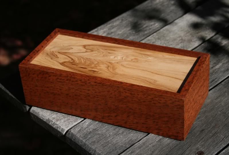
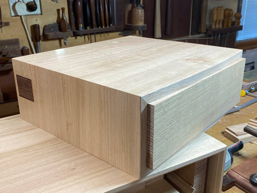
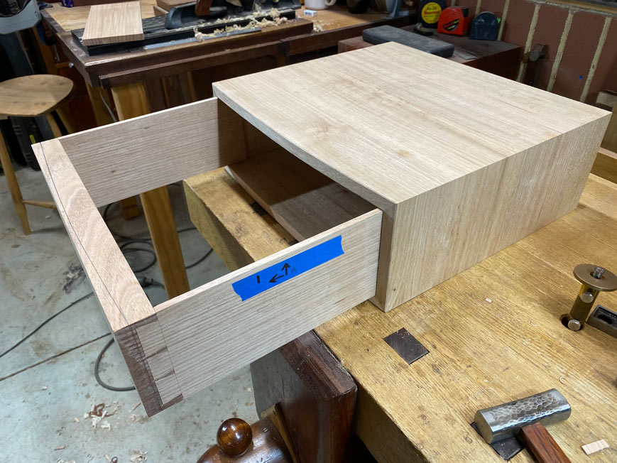
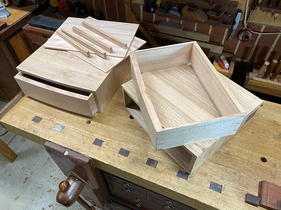
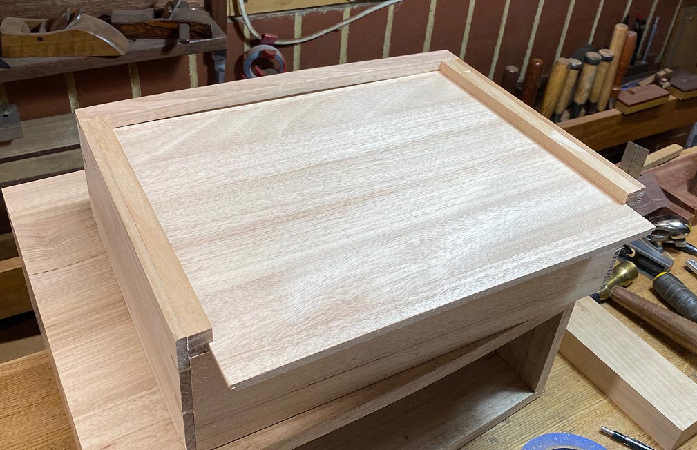
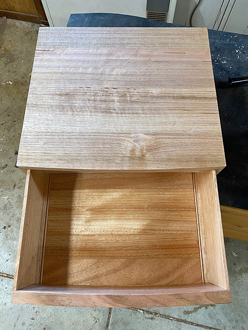
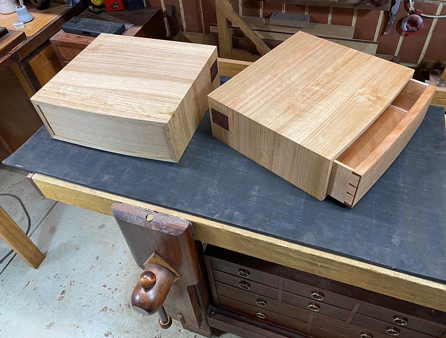
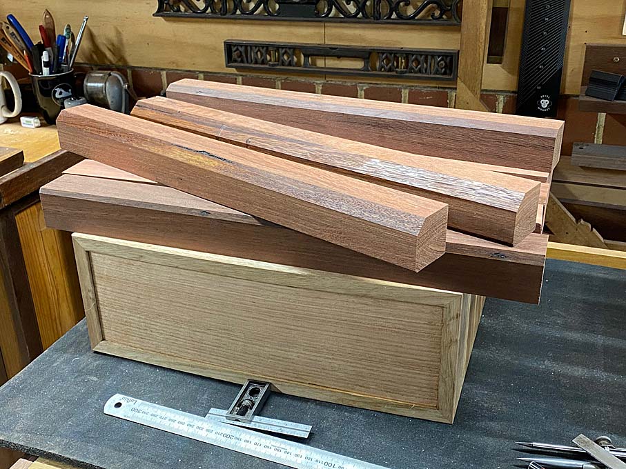
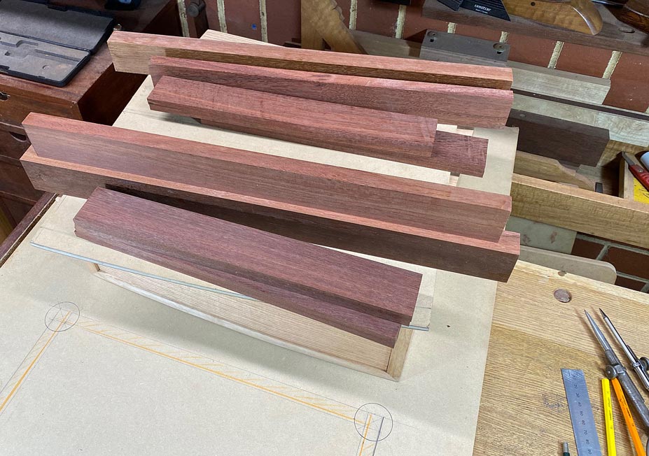
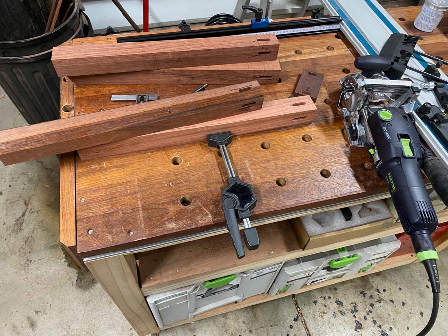
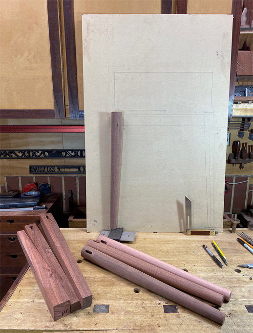
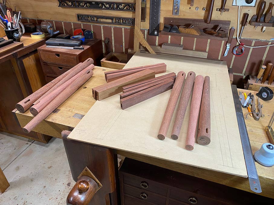
I am building two night stands. These are essentially Tasmanian Oak boxes on Jarrah stands, sort of Krevnovian in concept. Each will have a single, rectangular drawer, curved at the front, and with a small, window-like drawer at the side rear.
I am not doing a build this time, but will show photos at the end. What I do want to share is some of the construction of the basic boxes. These have mitred sides, and it is the making of the mitres which I think will interest Eliot.
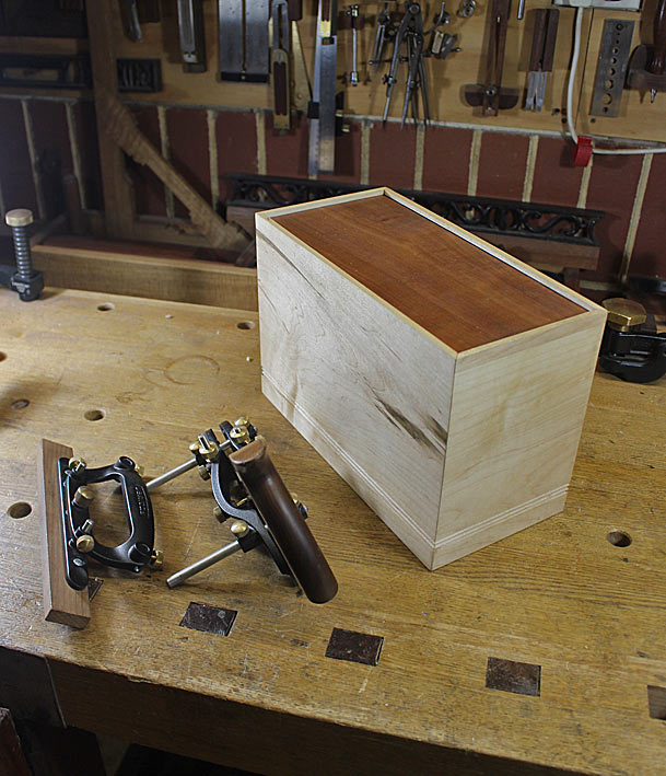
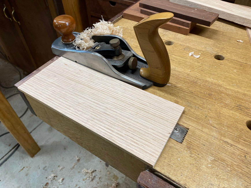
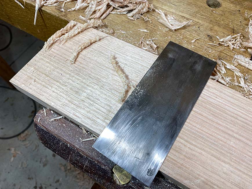
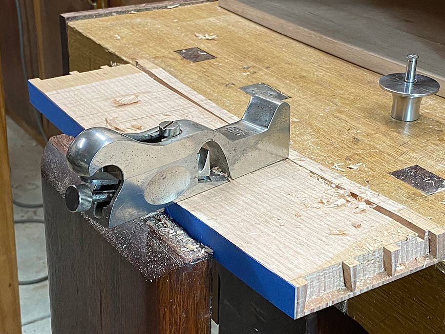
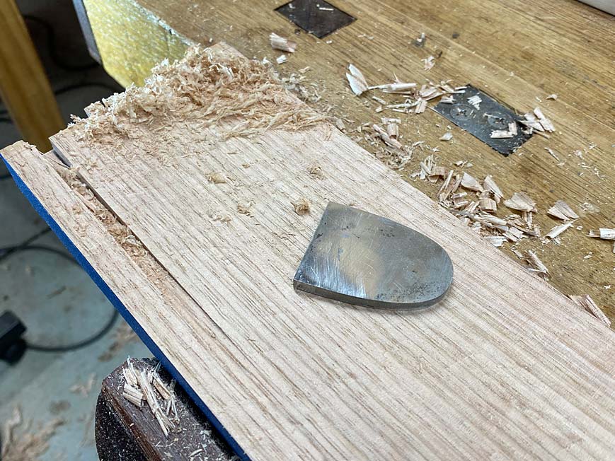
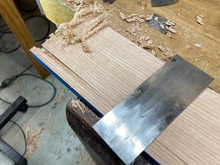
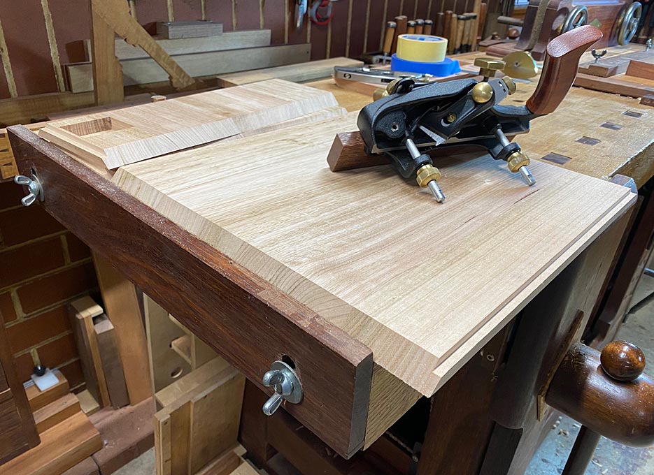
Two panels glued up. Here, removing the squeeze out with a cabinet scraper ...
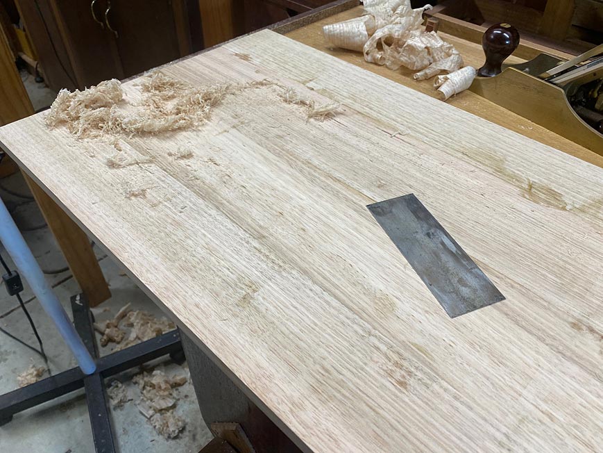
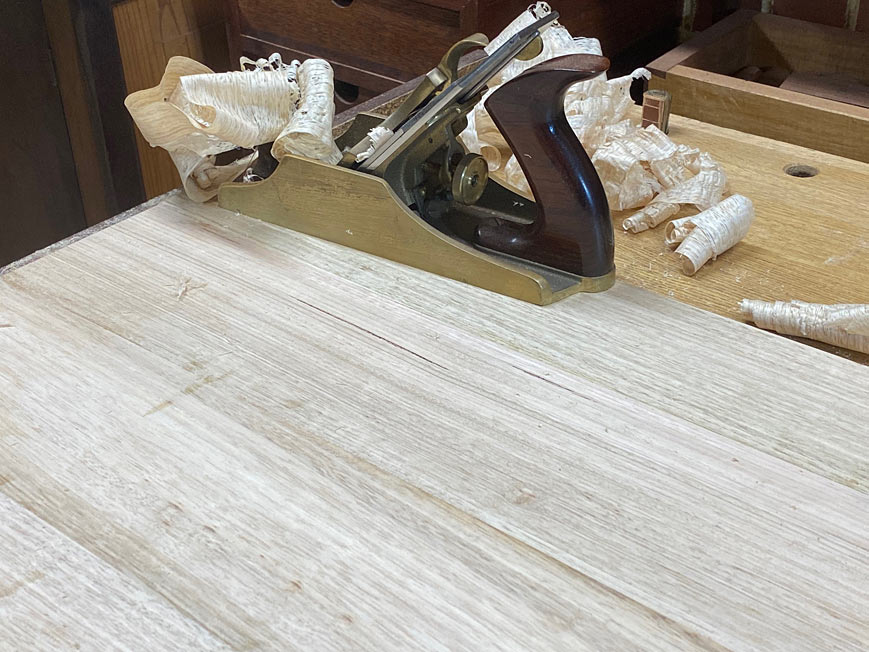
The Oak is quartersawn and the grain has rowed sections. This is alternating hard and soft striations, and tears out with the scraper. Smoothing the four-board panels with a LN #4 1/2 (the bronze Anniversary model), and closed up chipbreaker, leaves the surface smooth and clear ...
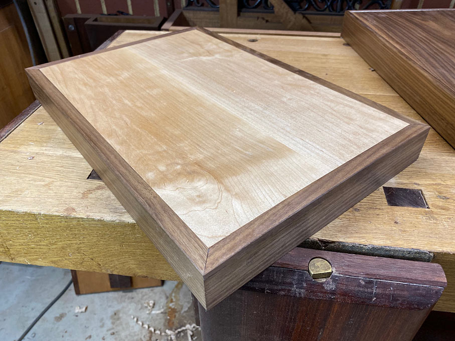
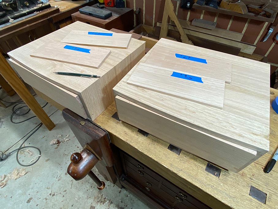
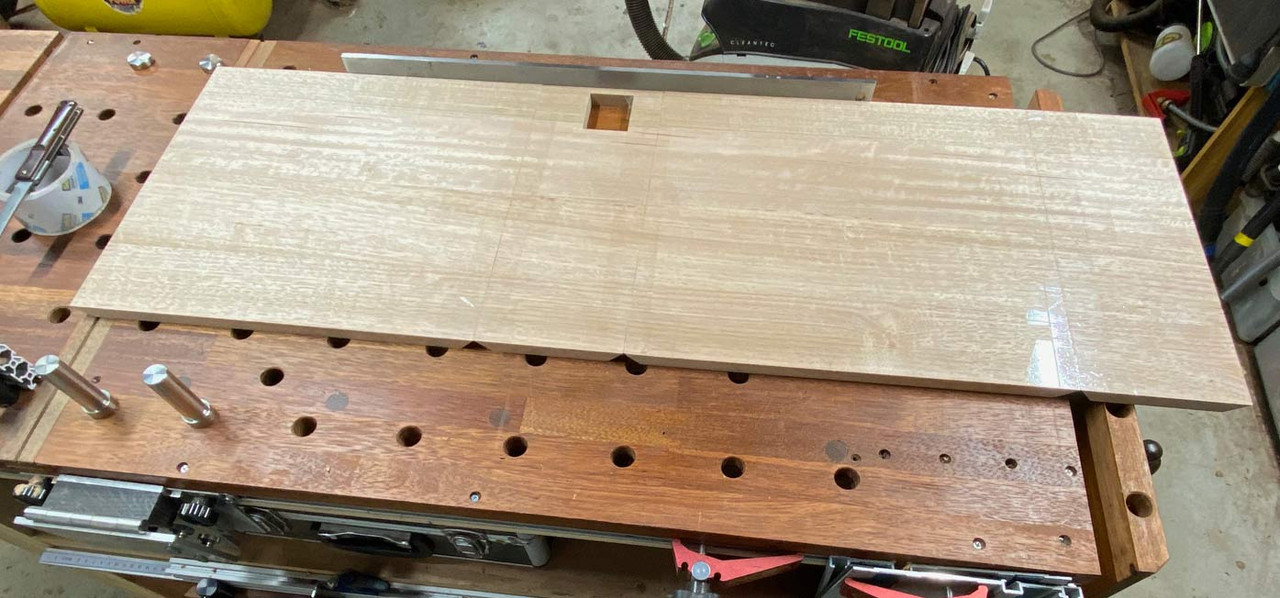
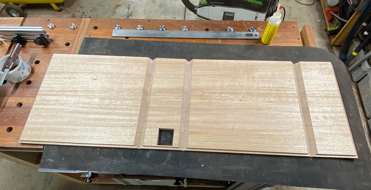
The panels are sawn into four sections - the four sides of the box - and the grain is arranged to flow around sequentially.
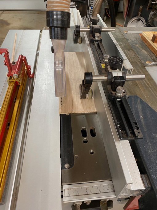
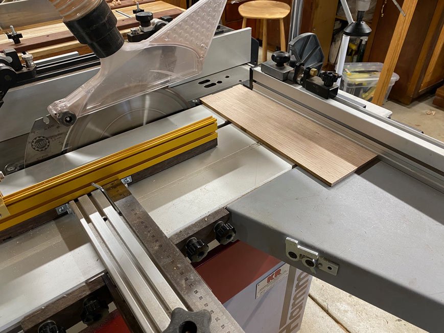
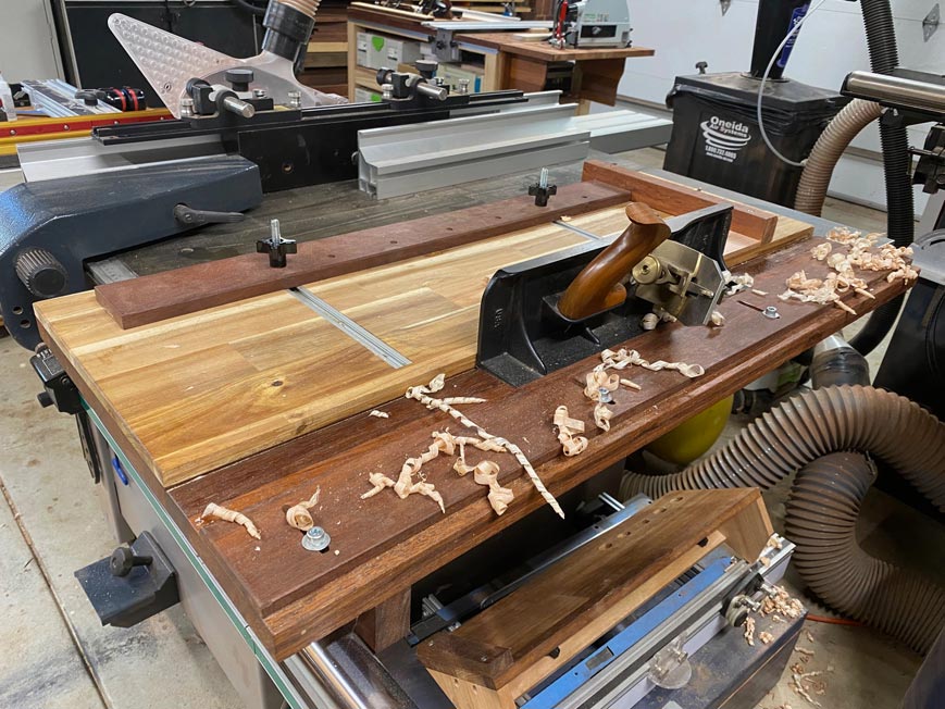
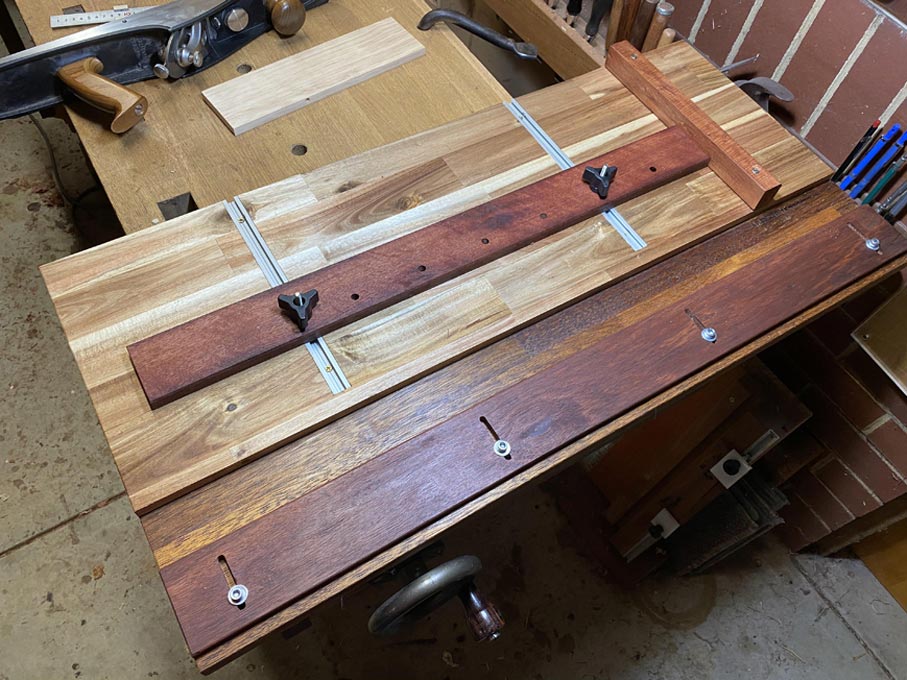
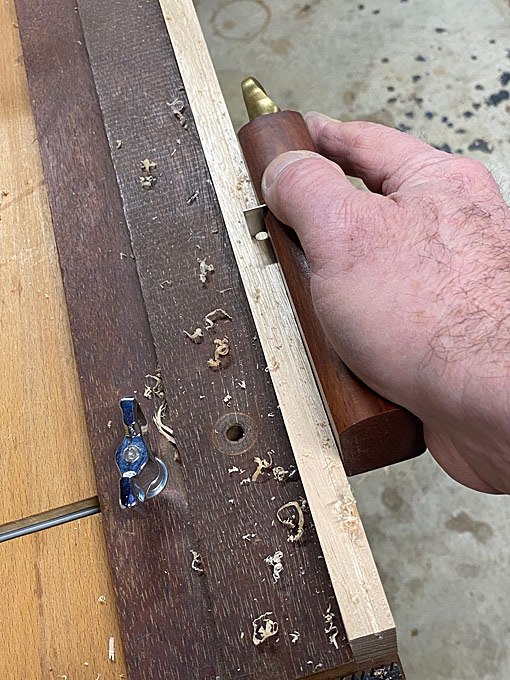
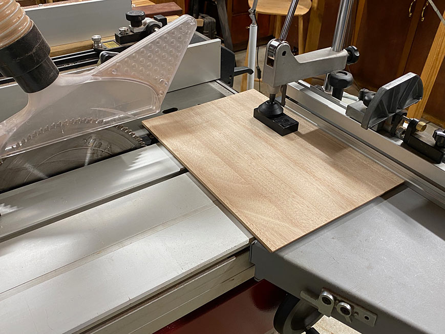
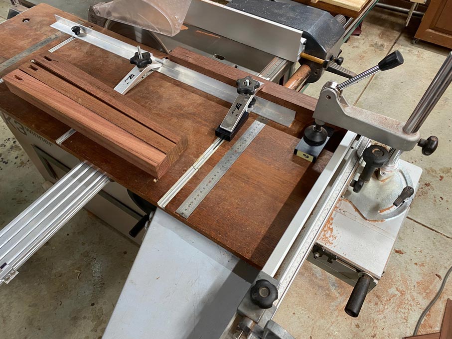
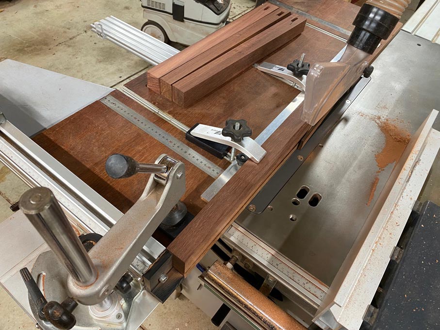
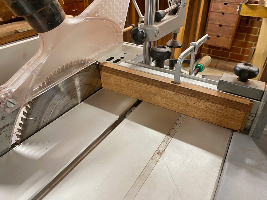
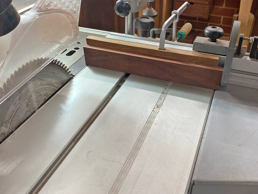
The mitres are cut on a sliding tablesaw, a Hammer K3. Here a side is being mitred, held on on side by a parallel guide I built. This essentially is a fence, like a rip fence, but the work piece is held stationary while it is moved past the blade ...
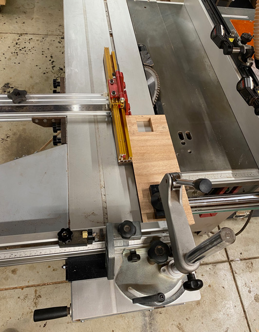
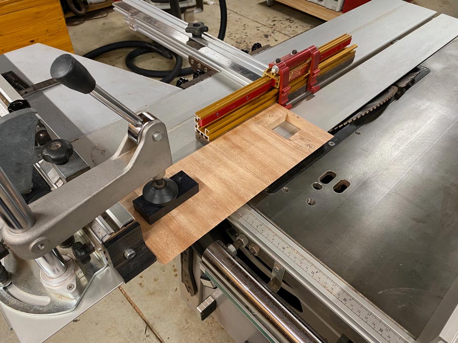
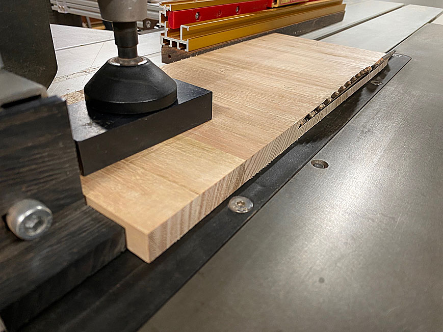
Once this is dialled in, all one has to do is flip the board for a perfect, parallel mitre on the opposite side.
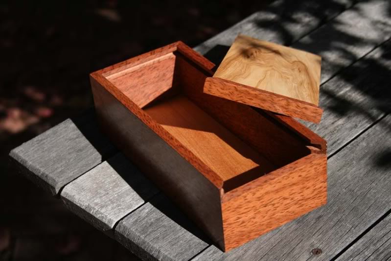
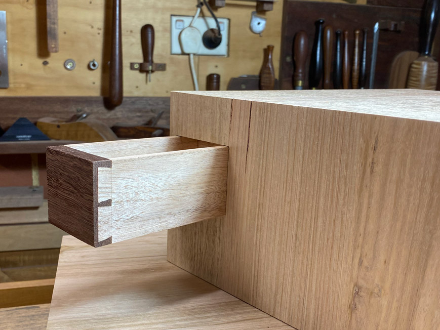
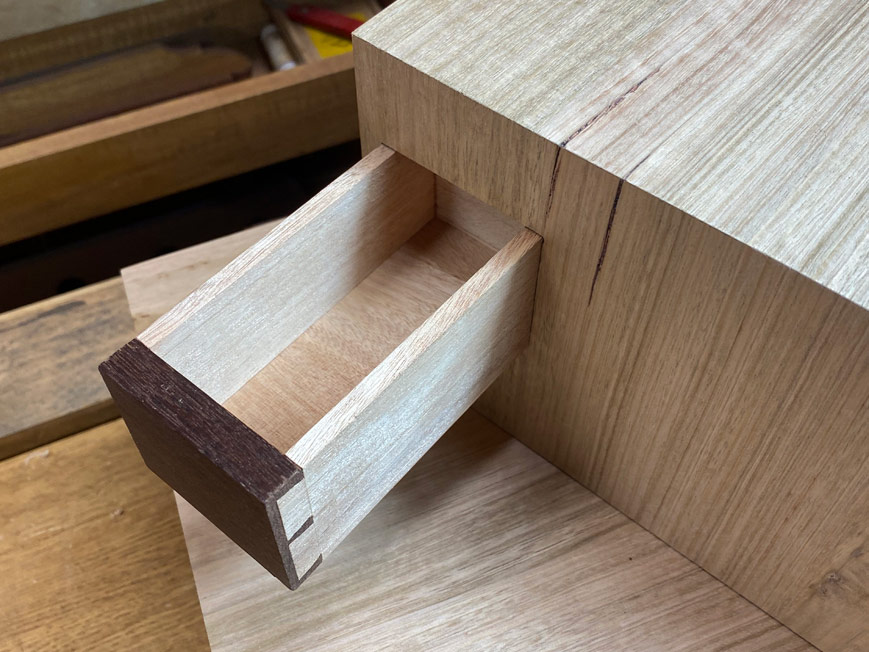
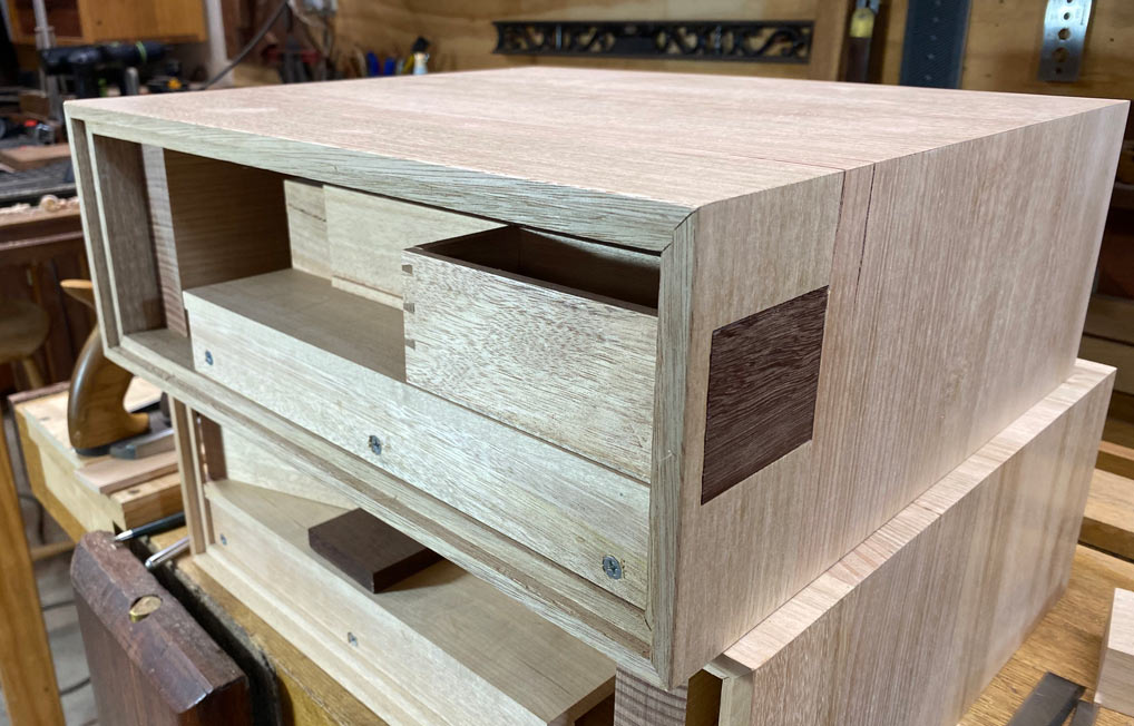
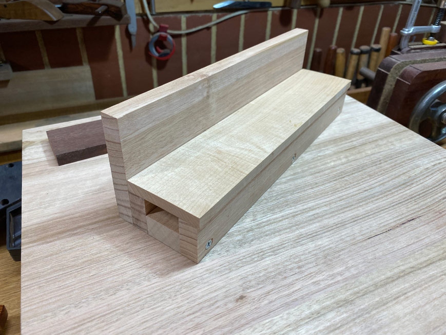
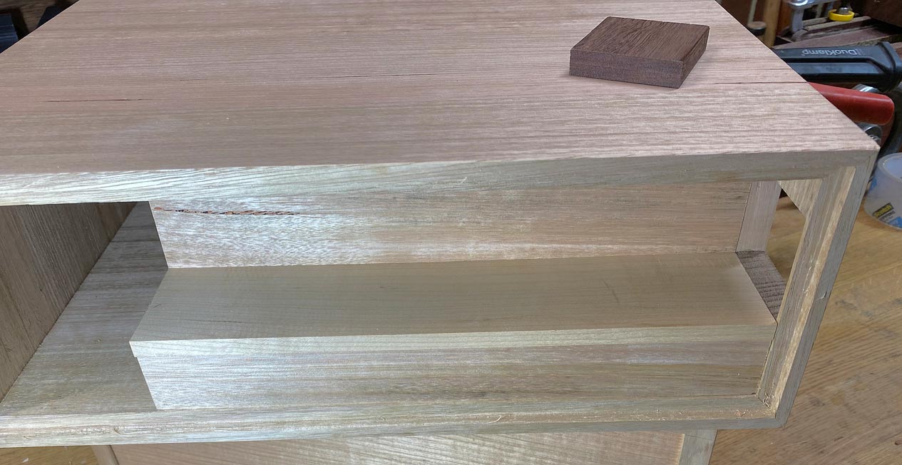
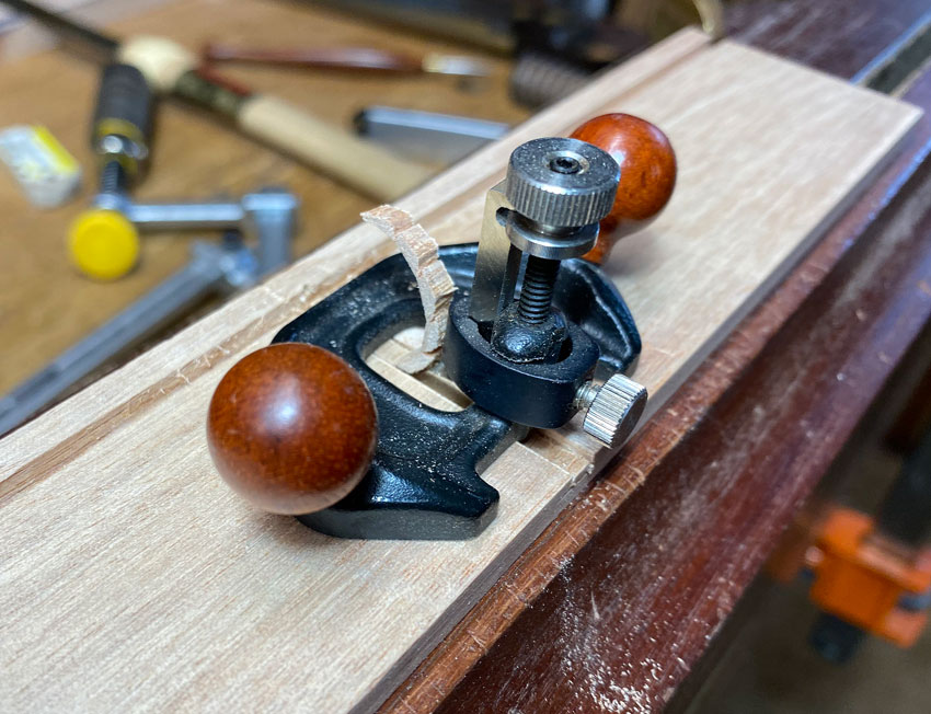
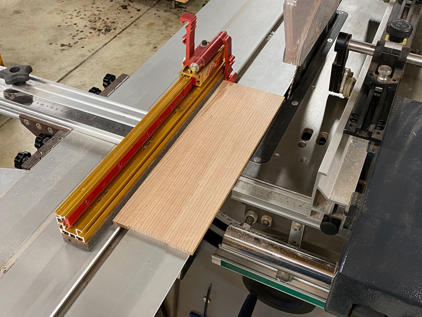
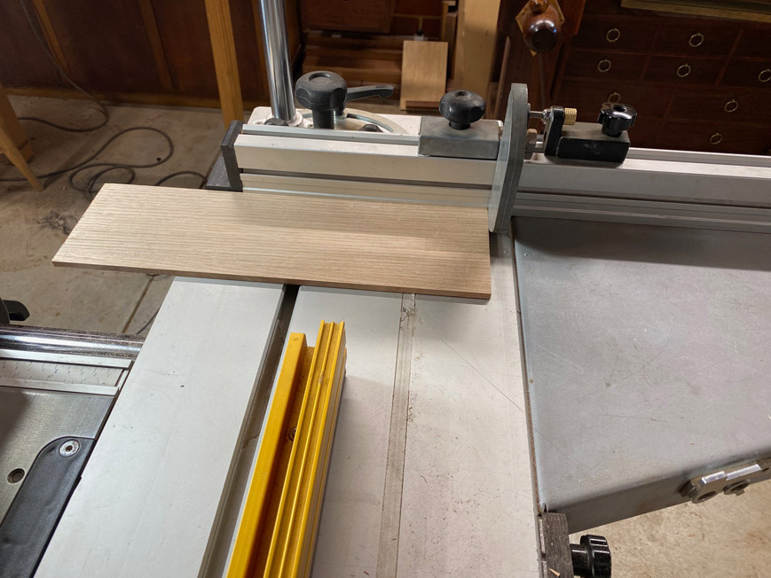
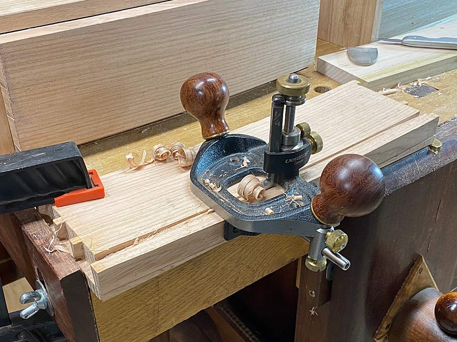
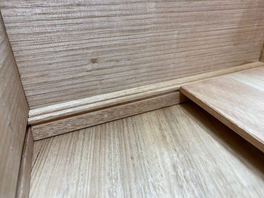
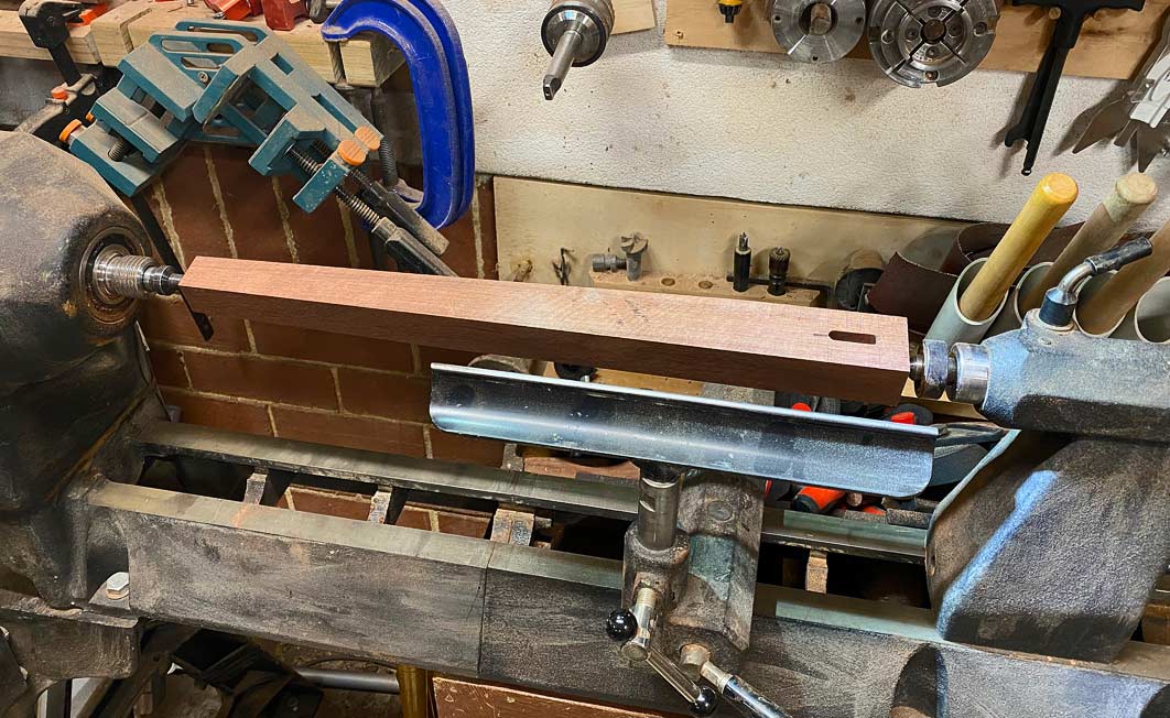
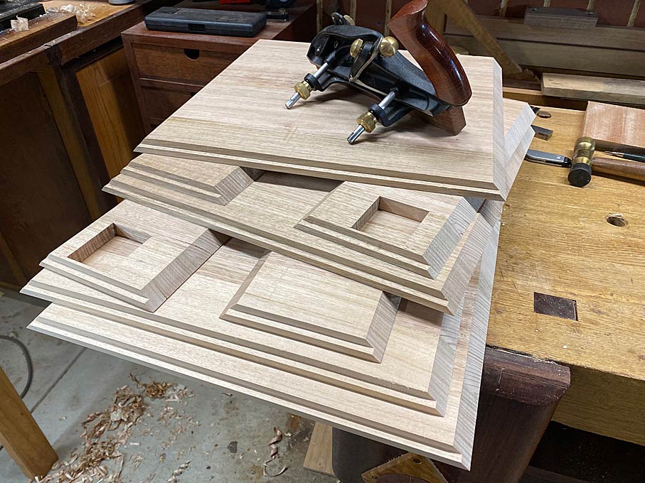
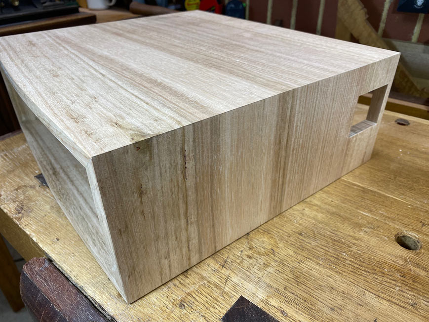
What is seen here is one of the sides with the opening for a little "window" drawer.
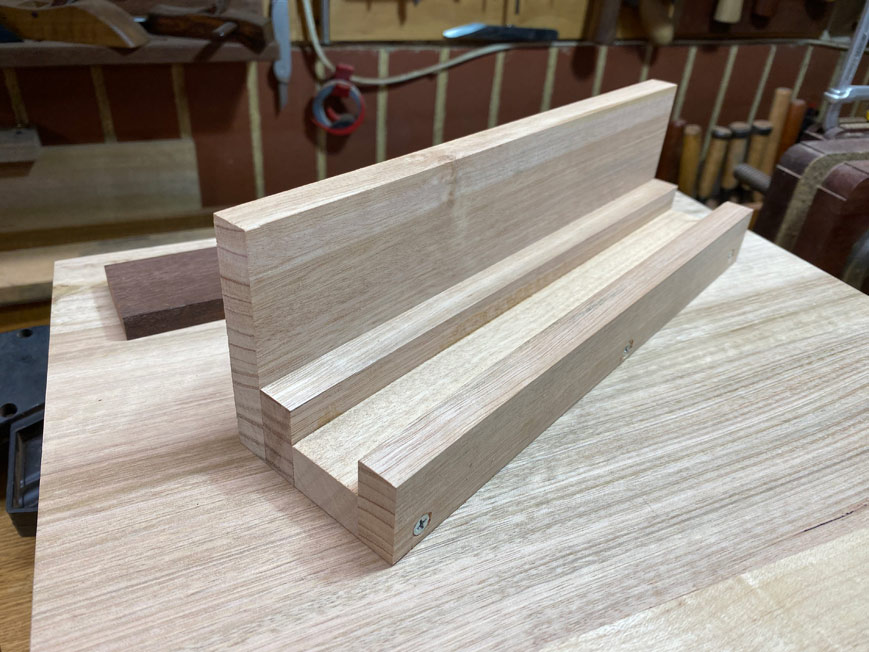
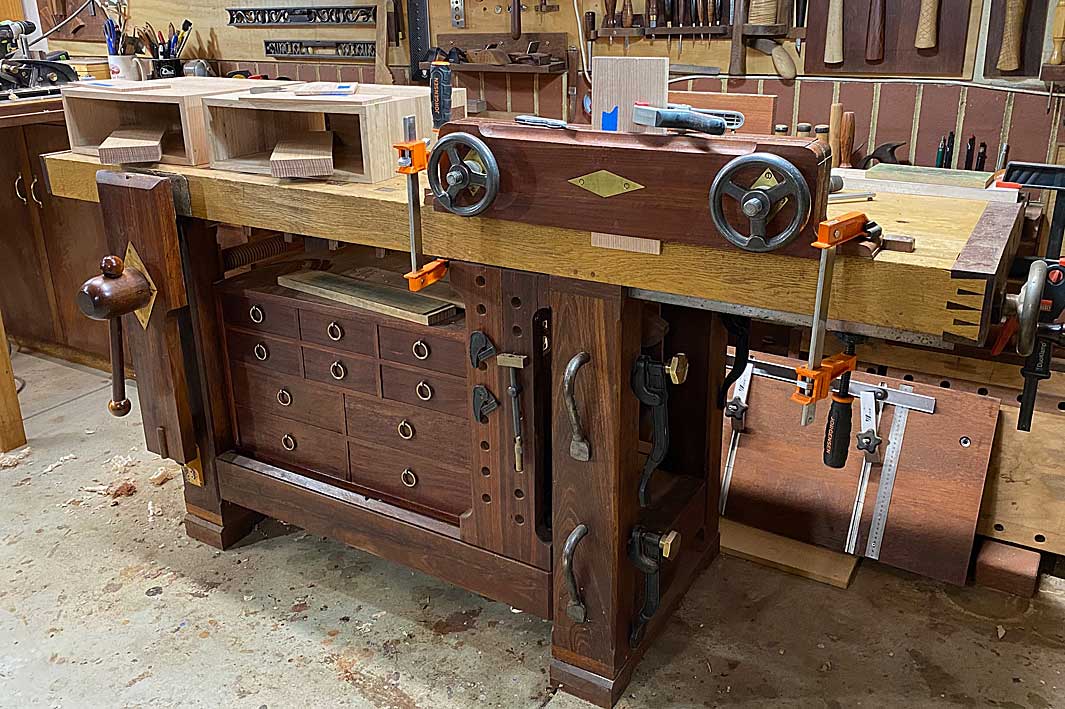
Linked to this, a few years ago I built a large ... giant! ... shooting board designed for jointing panels ...
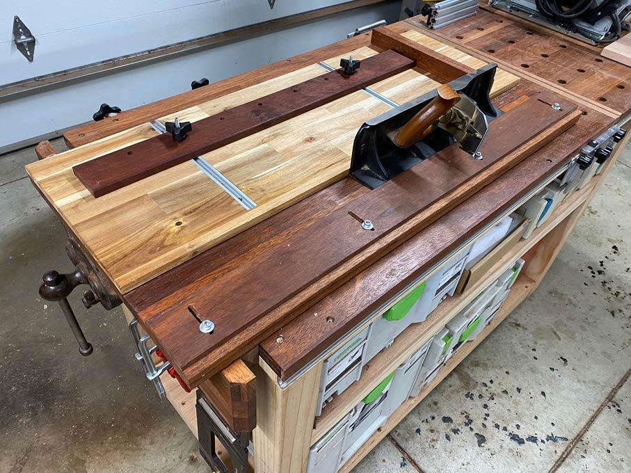
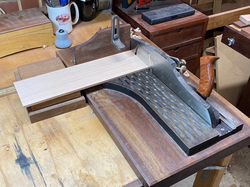
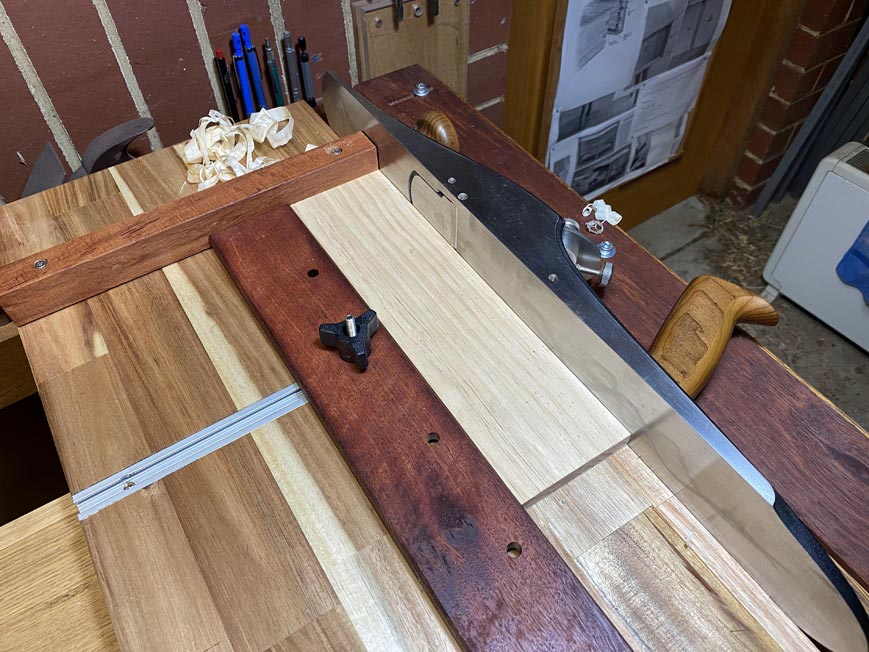
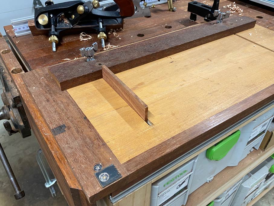
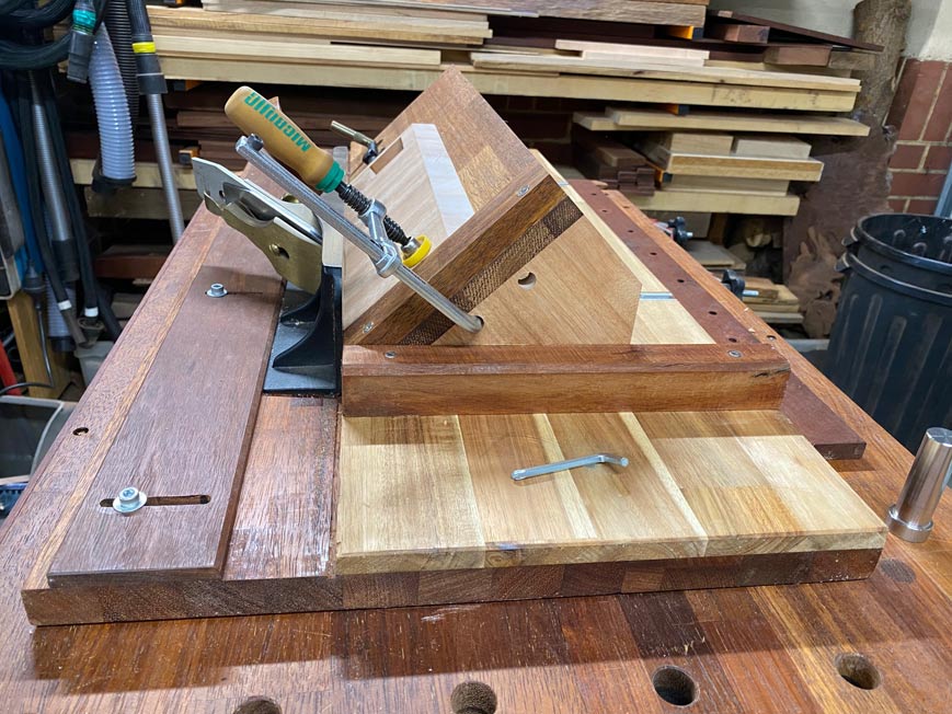
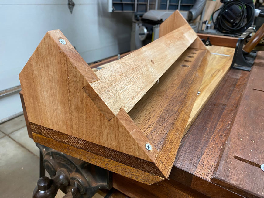
This has now been converted into a giant mitre shooting board ...
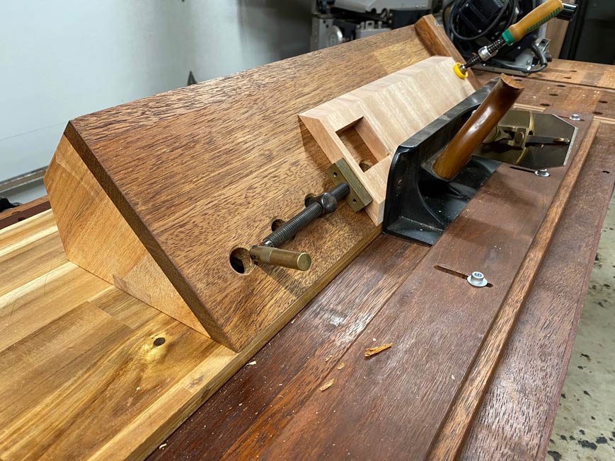
This is clamped down from the inside using the mitre tracks ...
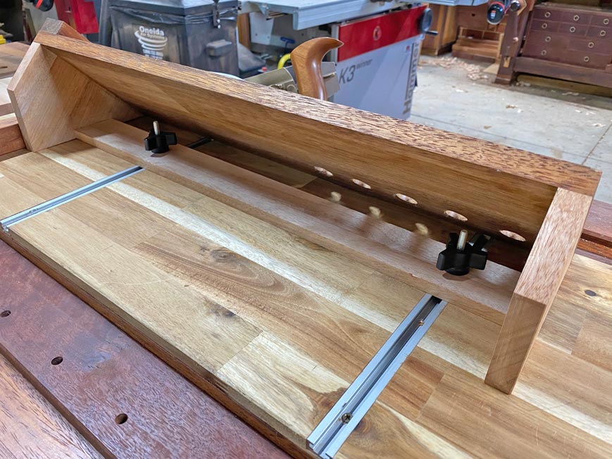
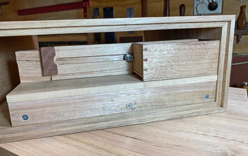
The underside, for those interested in the construction. The screws in the base are adjustable legs ...
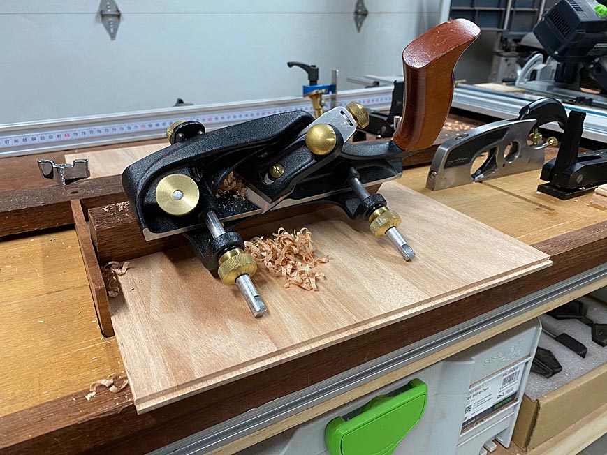
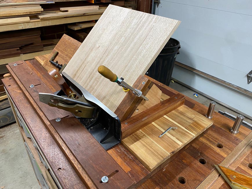
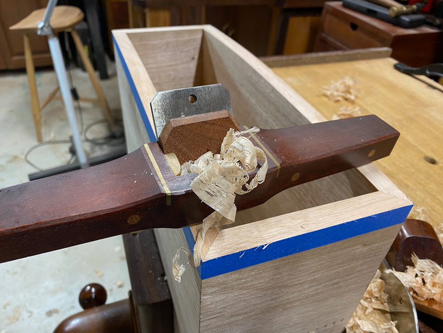
After sawing the mitres, the shooting board is used to ensure that these are perfectly straight for the cleanest possible joint ..
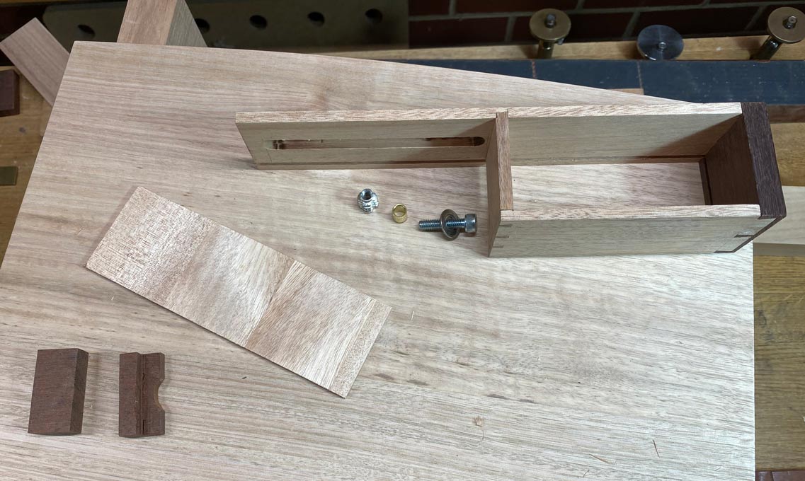
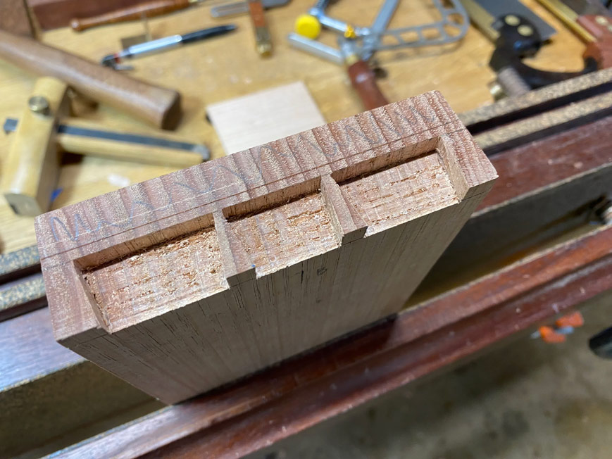
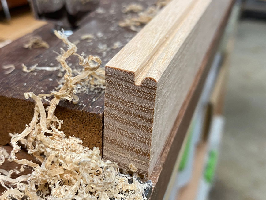
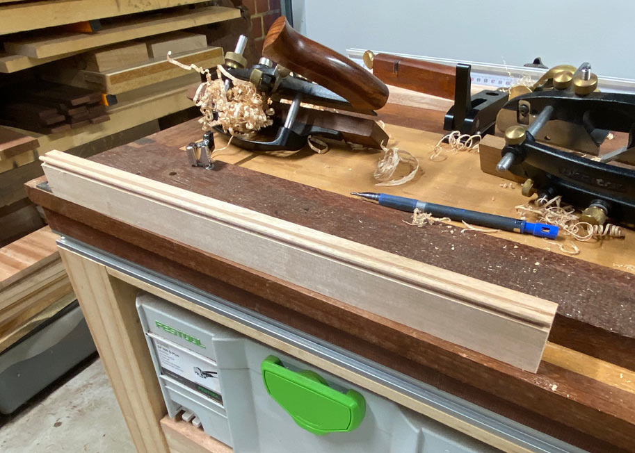
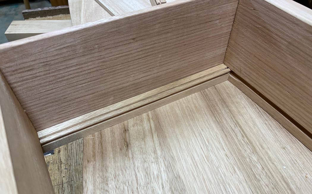
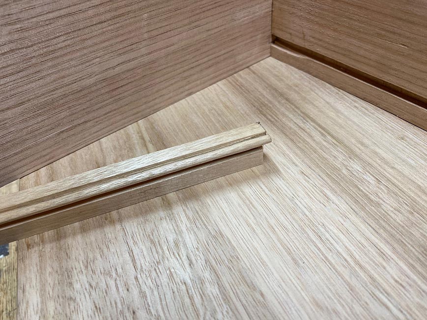
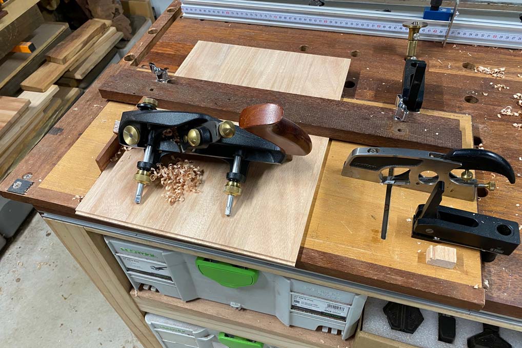
Now they require rebates at the rear of the panels.
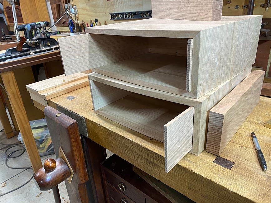
Finishing up with all these ...
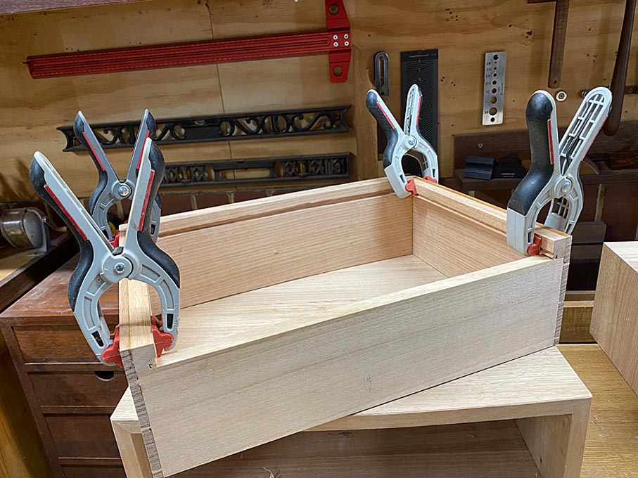
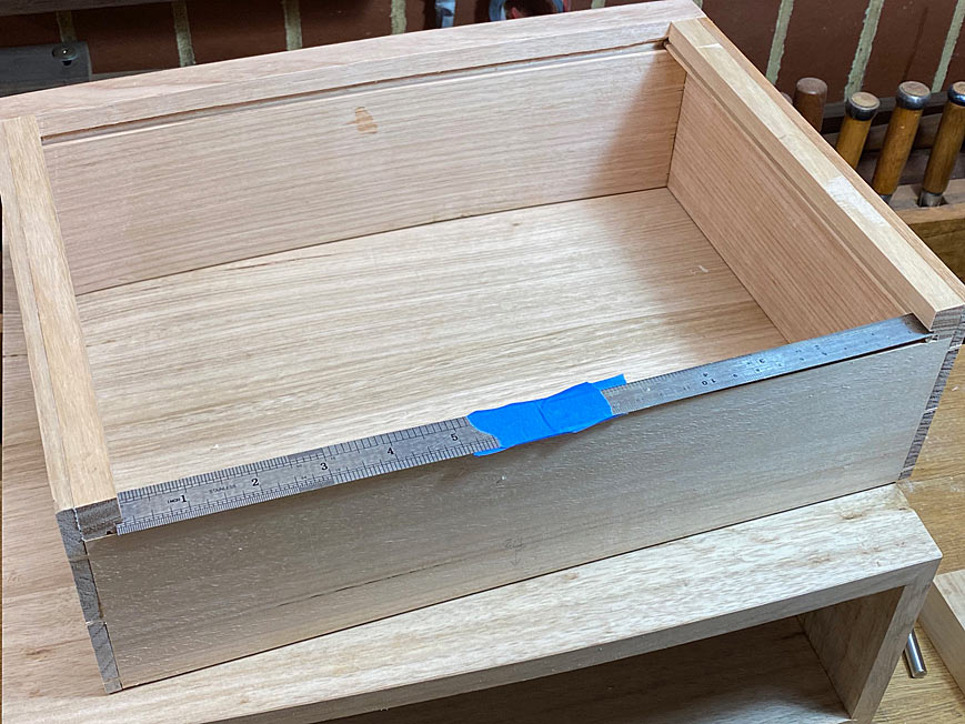
Time to tape together ...
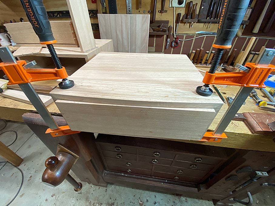
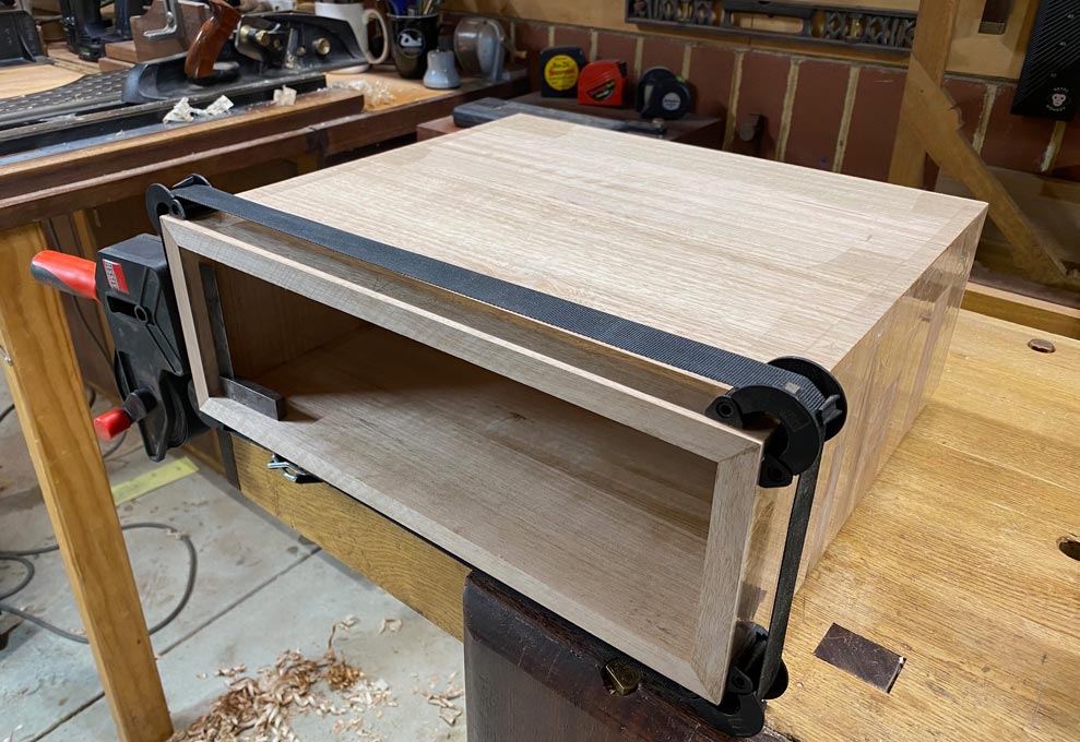
And glue up ..
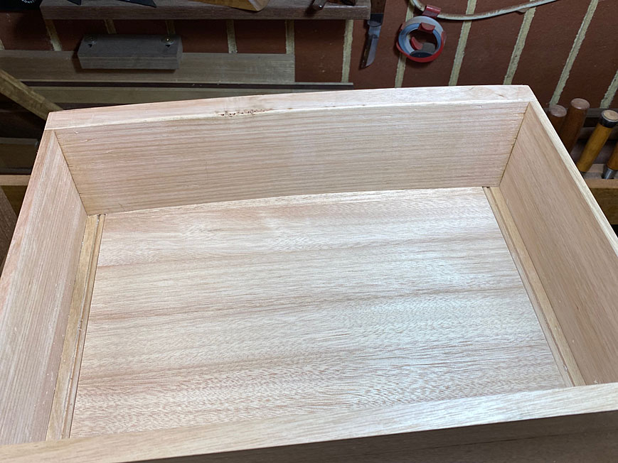
We ended here ..
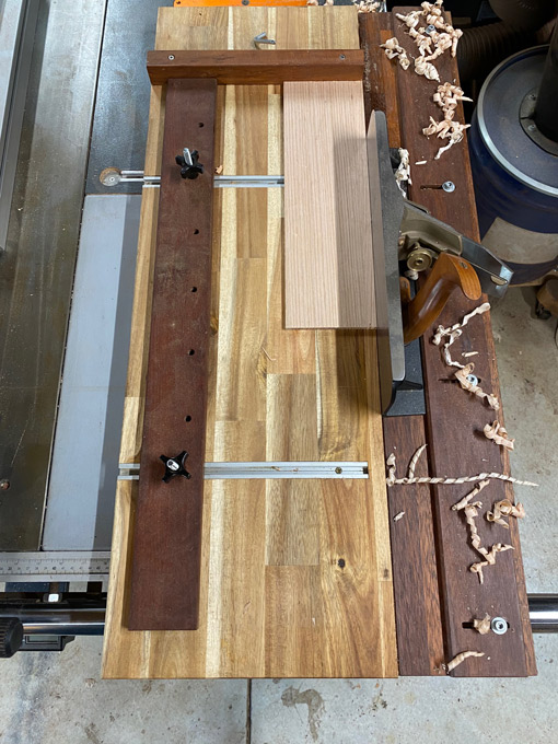
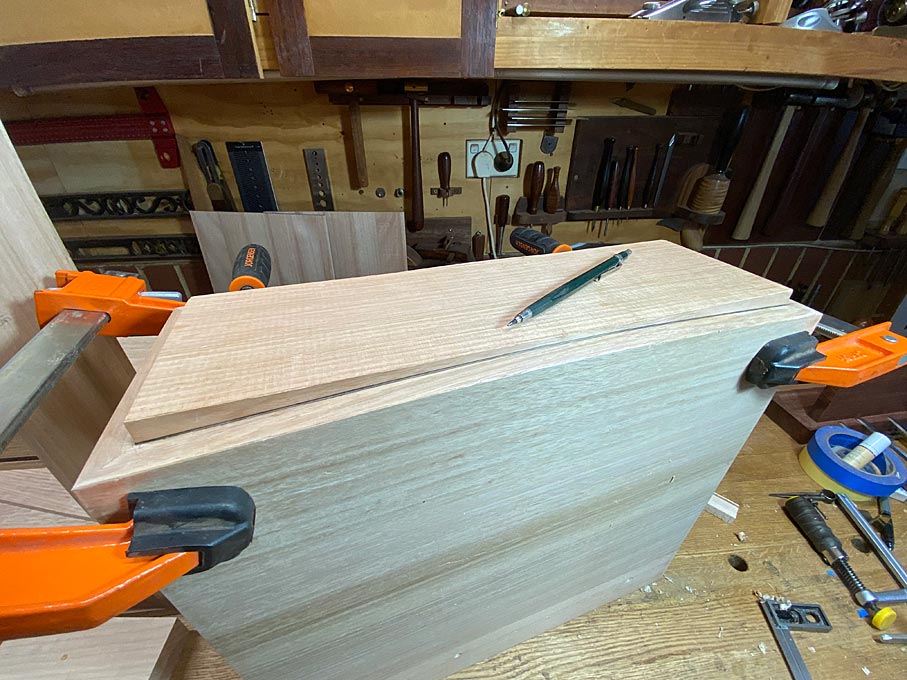
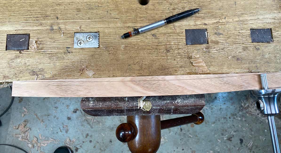
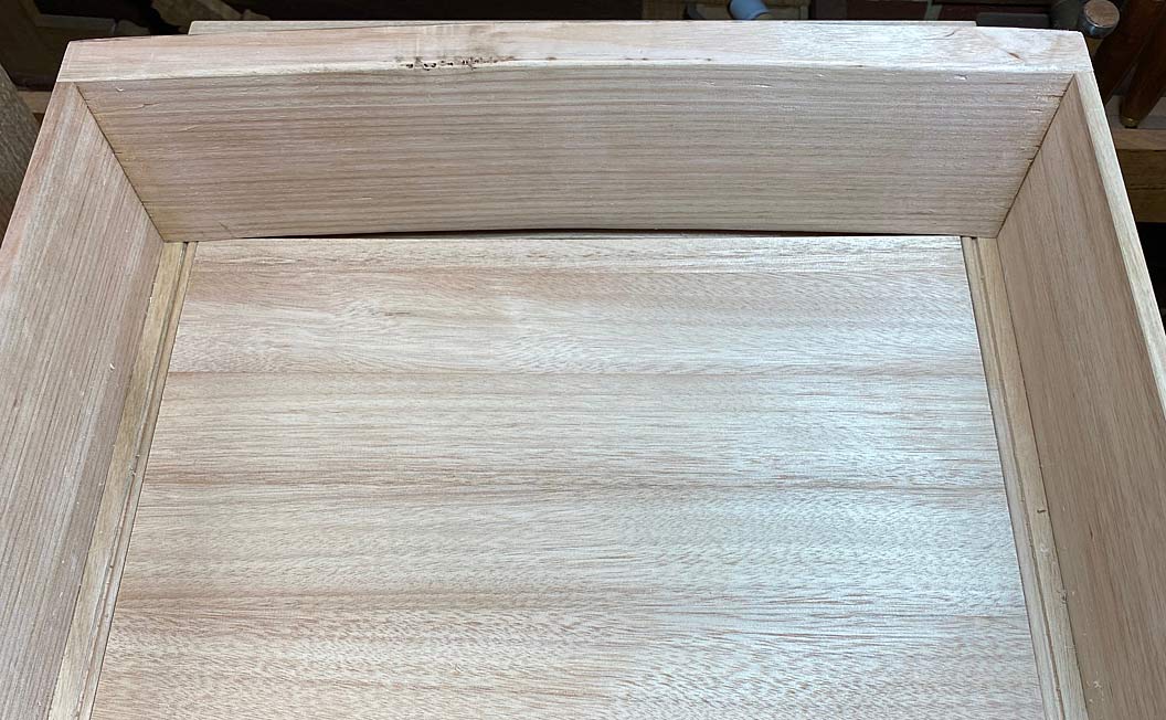
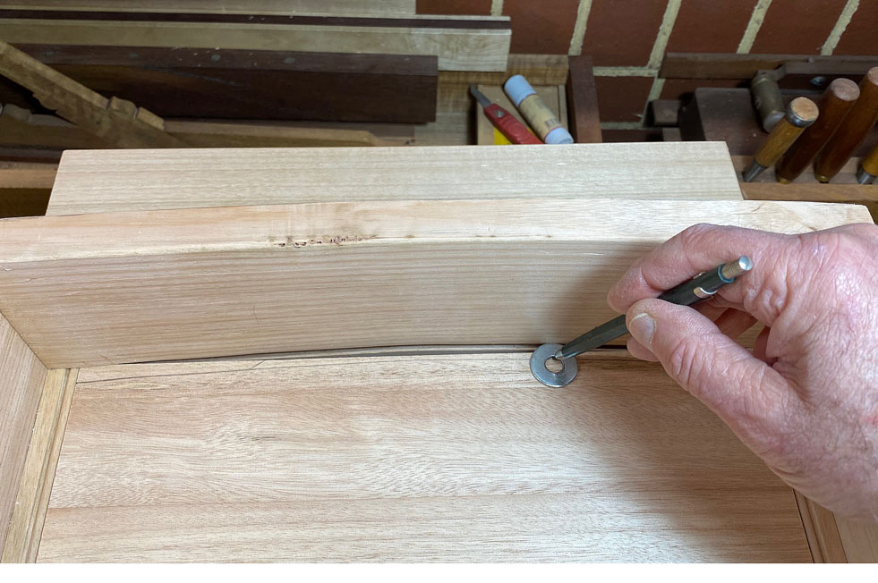
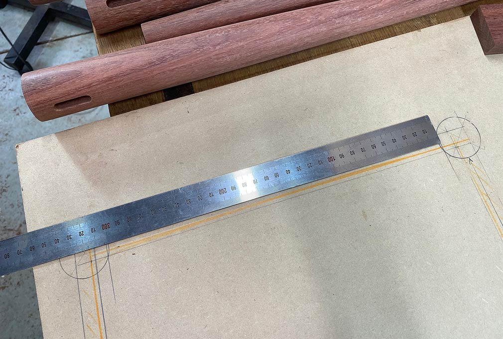
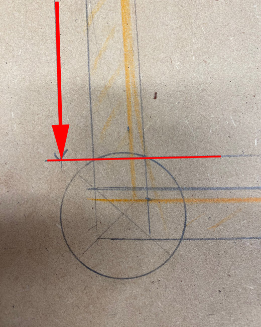
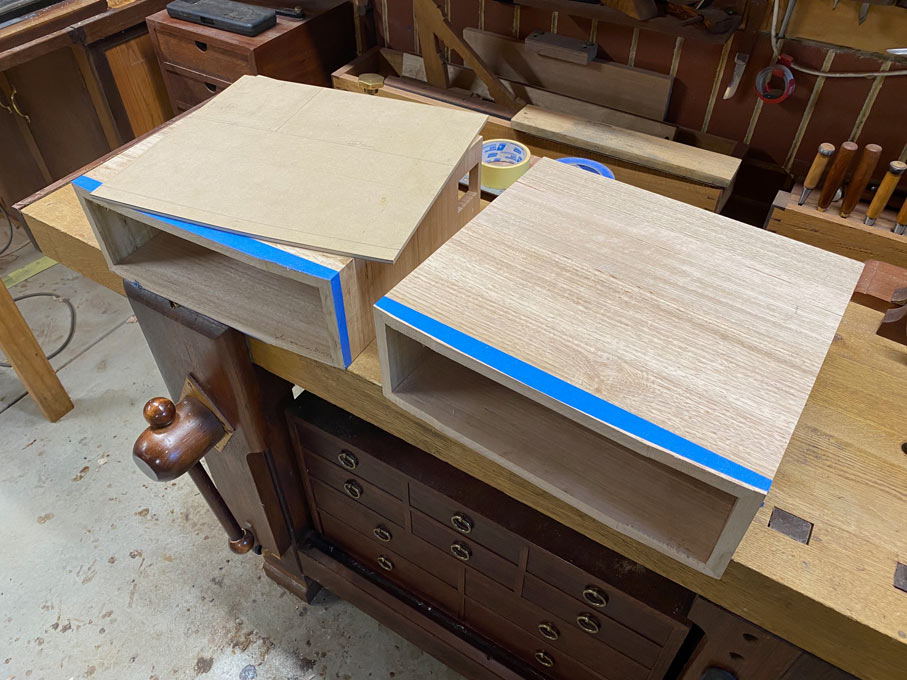
Today I made a template for the bow fronts, marked the curves , and used the bandsaw to remove most of the waste ...
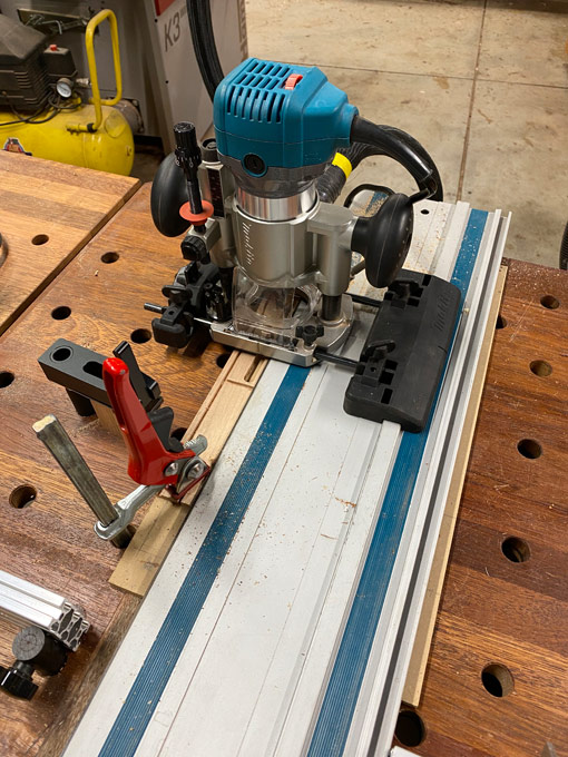
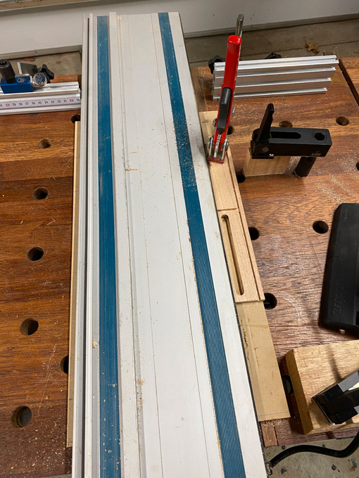
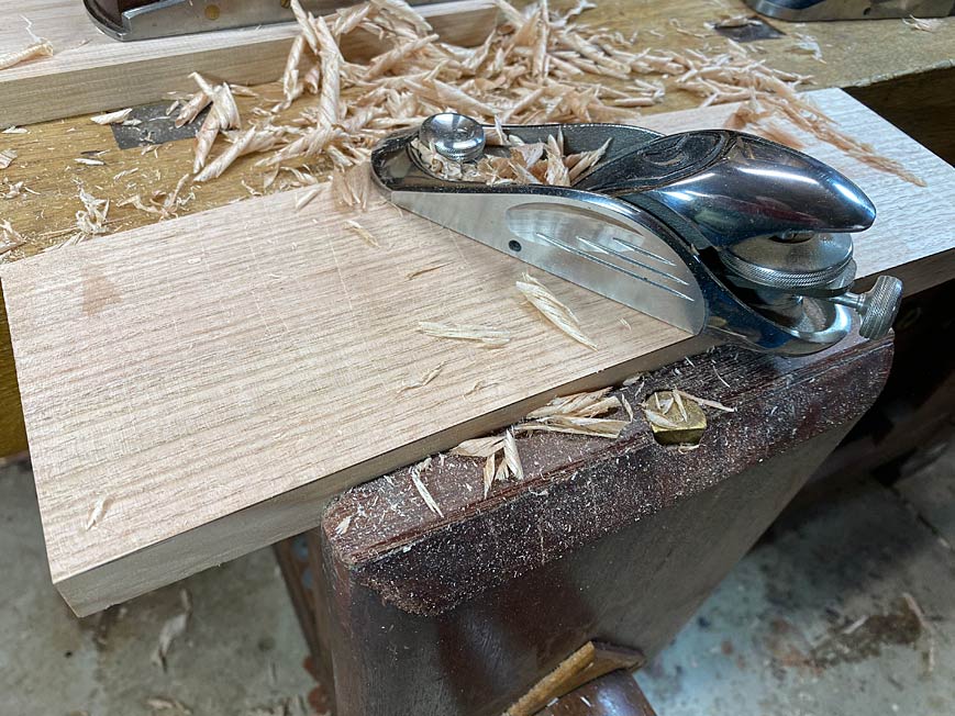
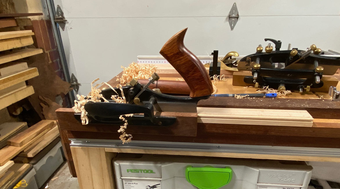
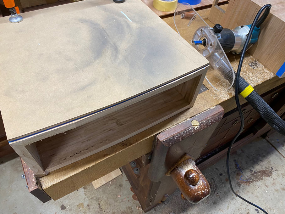
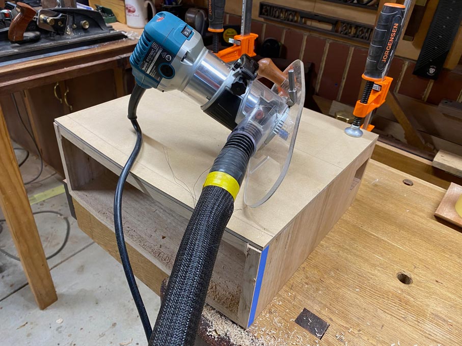
I contemplated cleaning this up with spokeshaves, then came to my senses and used a trim router and flush trim bearing ...
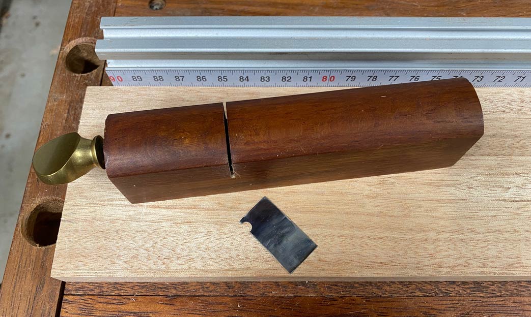
And cleaned up with a HNT Gordon spokeshave ...
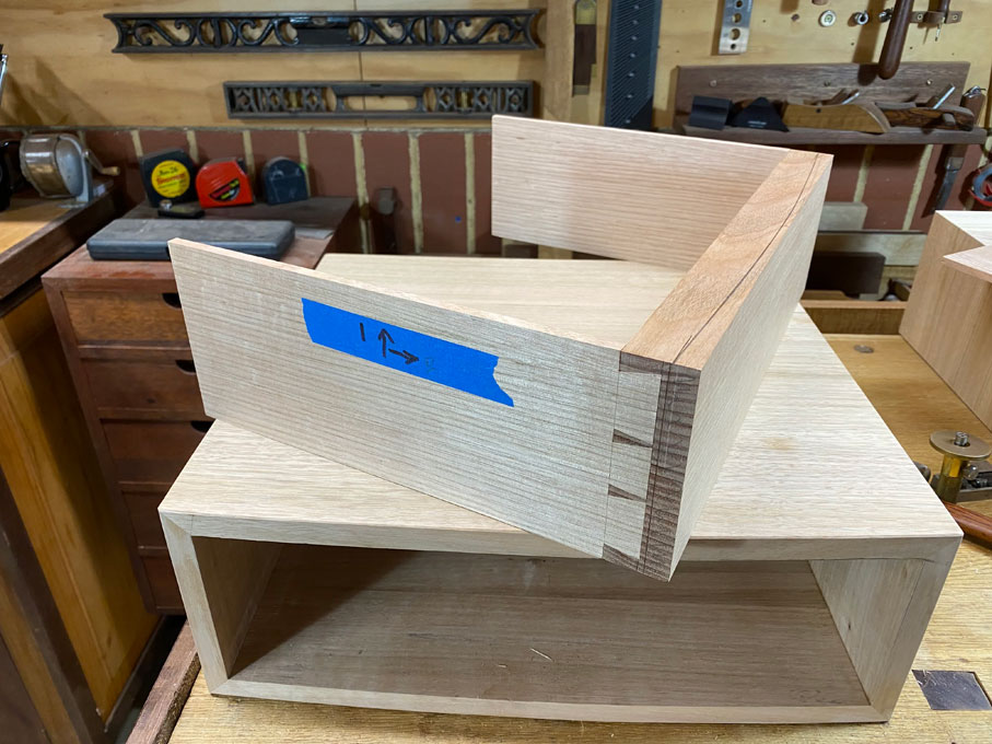
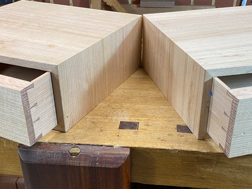
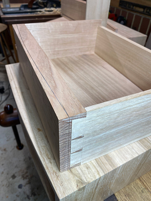
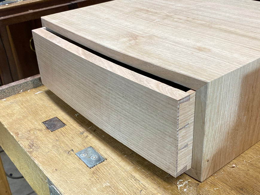
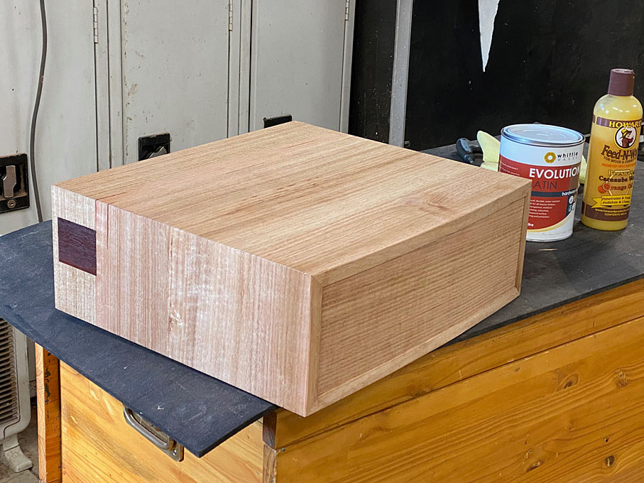
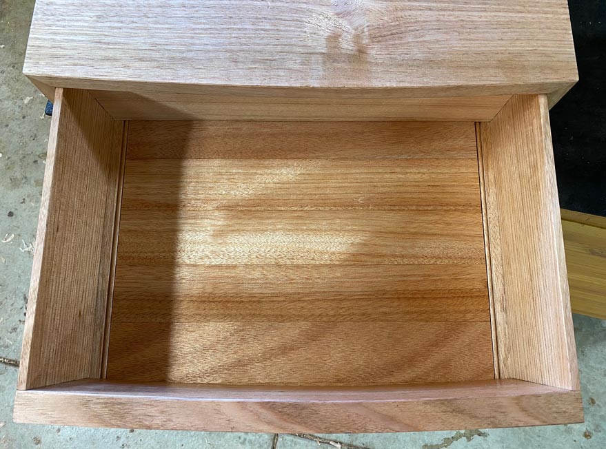
All the trouble at the start to make the mitres as clean and tight as possible. How did we do?
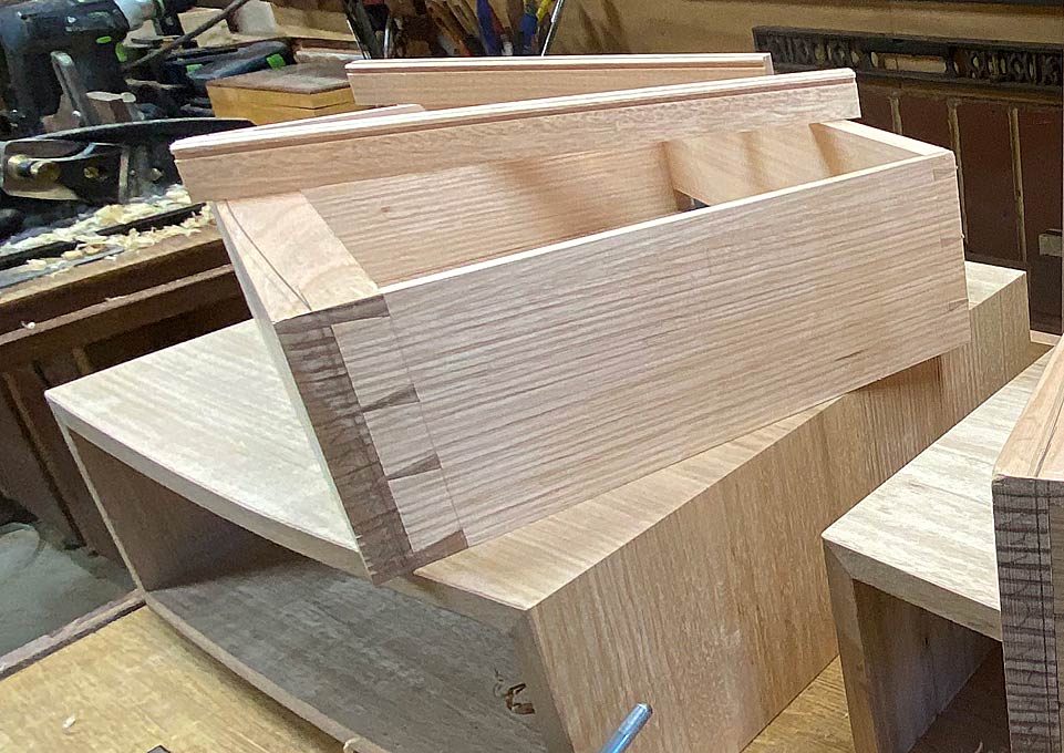
The rebates and mitres look good ...
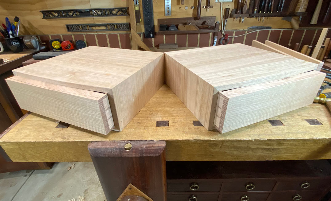
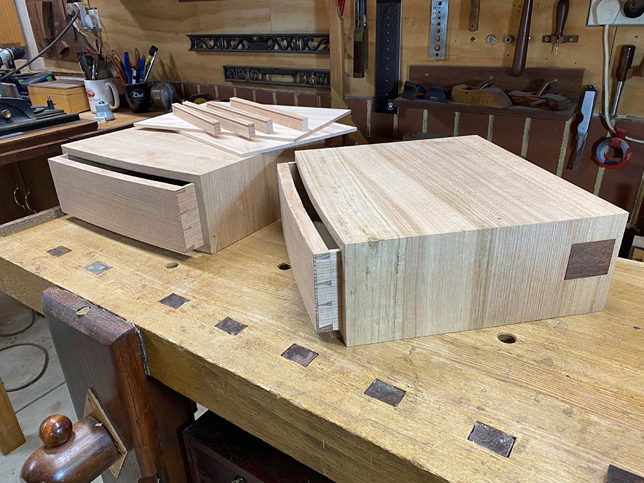
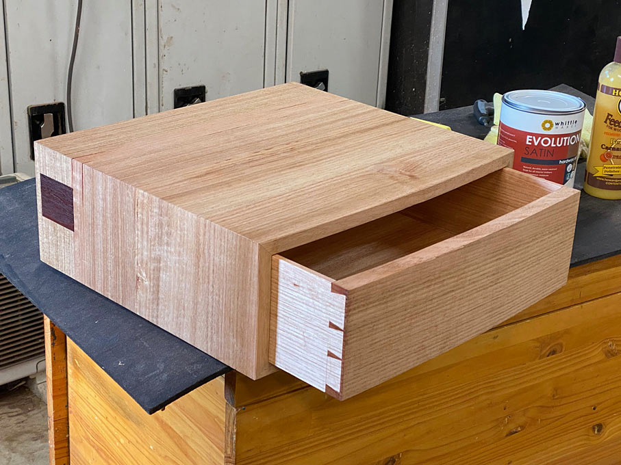
And I like the bow fronts ...
Tight mitres too

Regards from Perth
Derek
I am not doing a build this time, but will show photos at the end. What I do want to share is some of the construction of the basic boxes. These have mitred sides, and it is the making of the mitres which I think will interest Eliot.
Two panels glued up. Here, removing the squeeze out with a cabinet scraper ...
The Oak is quartersawn and the grain has rowed sections. This is alternating hard and soft striations, and tears out with the scraper. Smoothing the four-board panels with a LN #4 1/2 (the bronze Anniversary model), and closed up chipbreaker, leaves the surface smooth and clear ...
The panels are sawn into four sections - the four sides of the box - and the grain is arranged to flow around sequentially.
The mitres are cut on a sliding tablesaw, a Hammer K3. Here a side is being mitred, held on on side by a parallel guide I built. This essentially is a fence, like a rip fence, but the work piece is held stationary while it is moved past the blade ...
Once this is dialled in, all one has to do is flip the board for a perfect, parallel mitre on the opposite side.
What is seen here is one of the sides with the opening for a little "window" drawer.
Linked to this, a few years ago I built a large ... giant! ... shooting board designed for jointing panels ...
This has now been converted into a giant mitre shooting board ...
This is clamped down from the inside using the mitre tracks ...
The underside, for those interested in the construction. The screws in the base are adjustable legs ...
After sawing the mitres, the shooting board is used to ensure that these are perfectly straight for the cleanest possible joint ..
Now they require rebates at the rear of the panels.
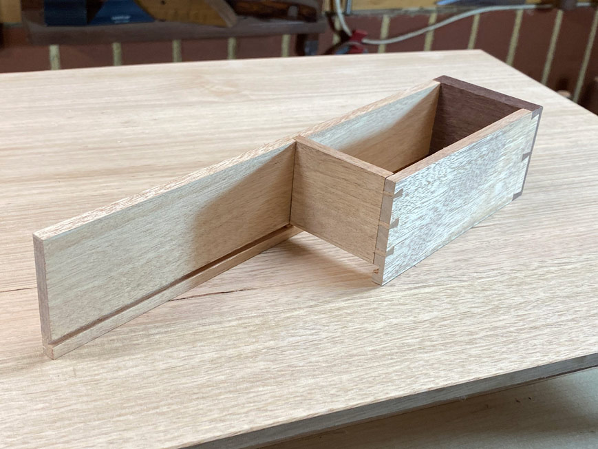
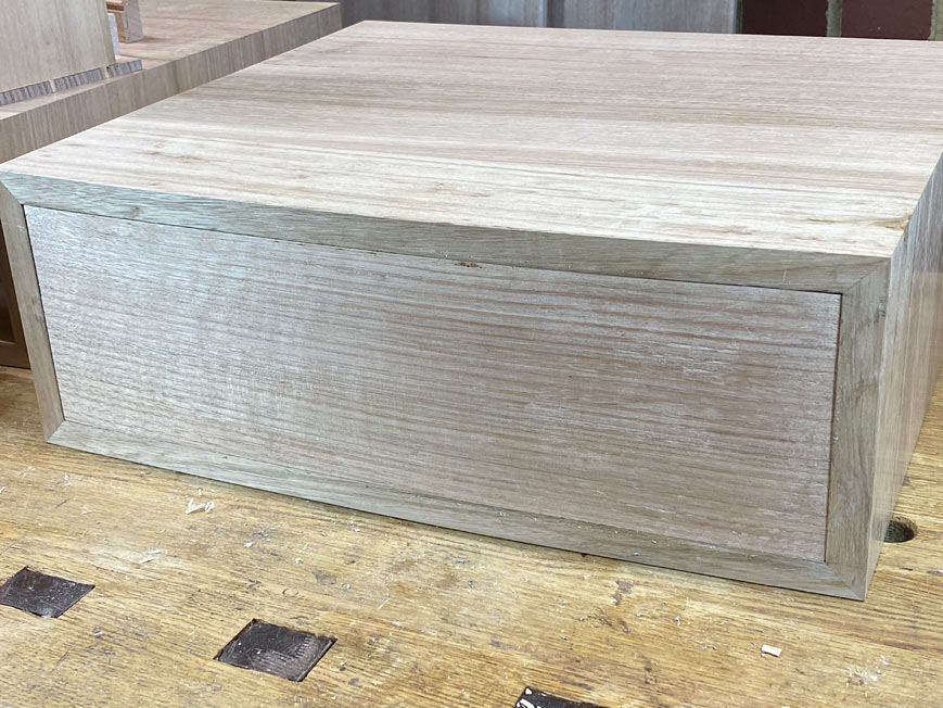
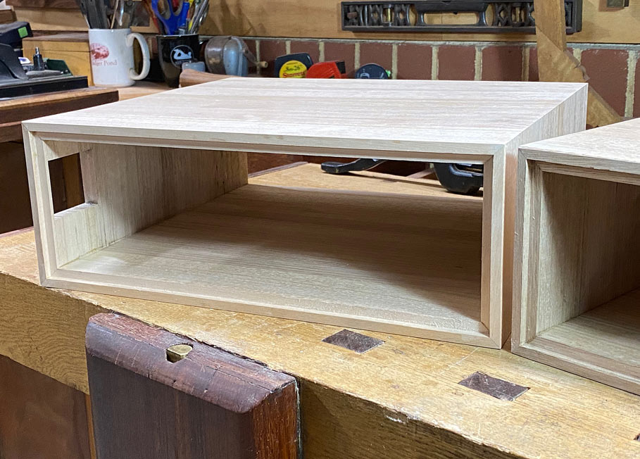
Finishing up with all these ...
Time to tape together ...
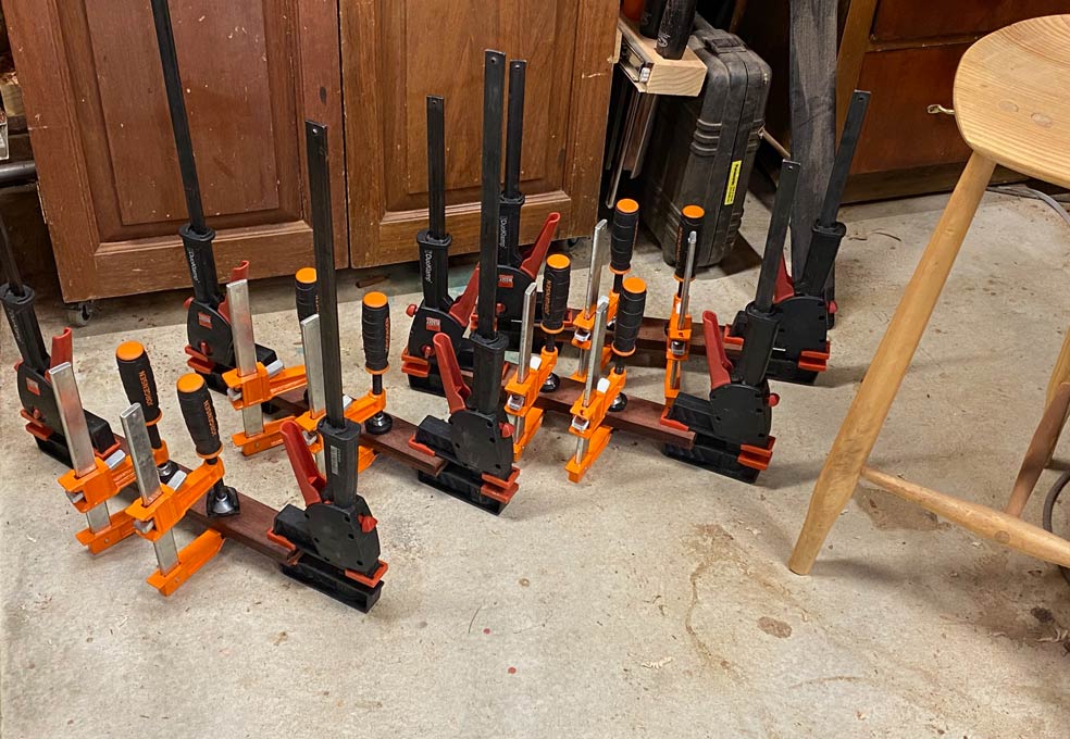
And glue up ..
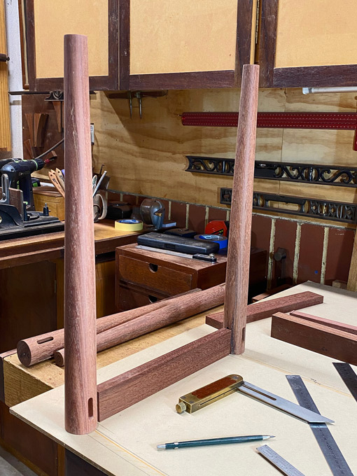
We ended here ..
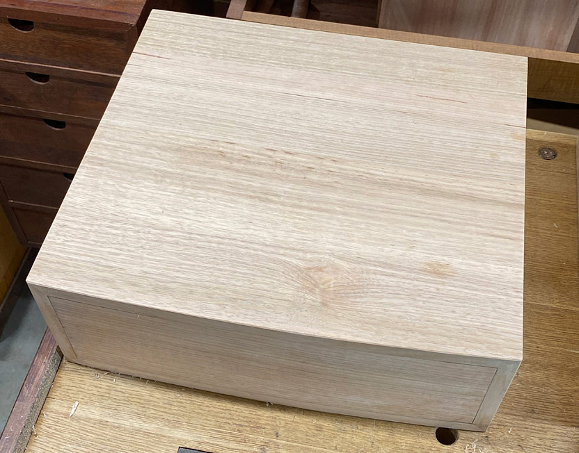
Today I made a template for the bow fronts, marked the curves , and used the bandsaw to remove most of the waste ...
I contemplated cleaning this up with spokeshaves, then came to my senses and used a trim router and flush trim bearing ...
And cleaned up with a HNT Gordon spokeshave ...
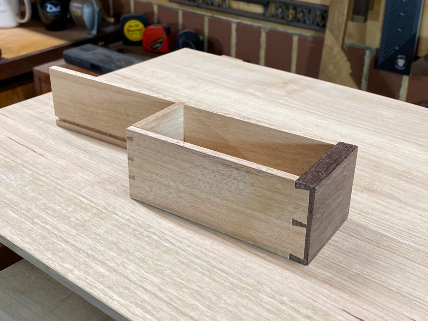
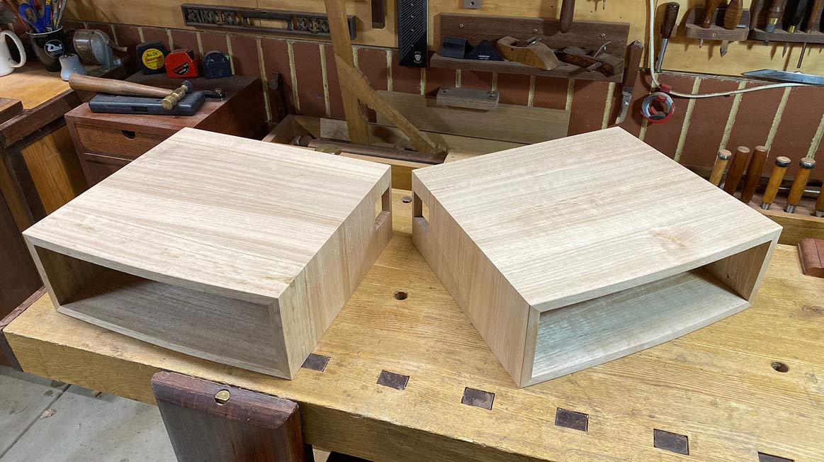
All the trouble at the start to make the mitres as clean and tight as possible. How did we do?
The rebates and mitres look good ...
And I like the bow fronts ...
Tight mitres too
Regards from Perth
Derek
Last edited: