Steampunk Mitrebox

UKworkshop.co.uk

Help Support UKworkshop.co.uk:

This site may earn a commission from merchant affiliate links, including eBay, Amazon, and others.

Derek Cohen (Perth Oz)

Established Member
Joined
2 Mar 2005
Messages
3,403
Reaction score
1,940
Location
Perth, Australia
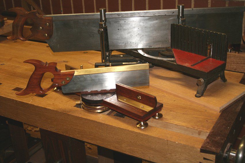
During my recent build of the kist I was sawing mouldings on a Millers Falls Acme 74A, and realised that it was similar to cracking nuts with a sledgehammer. I would kill for a small version of this mitrebox, but they are rare as rocking horse droppings and twice as expensive.

I usually build a tool between furniture projects and, consequently, decided this one would be my own version of a small MF .... well, sort of ...

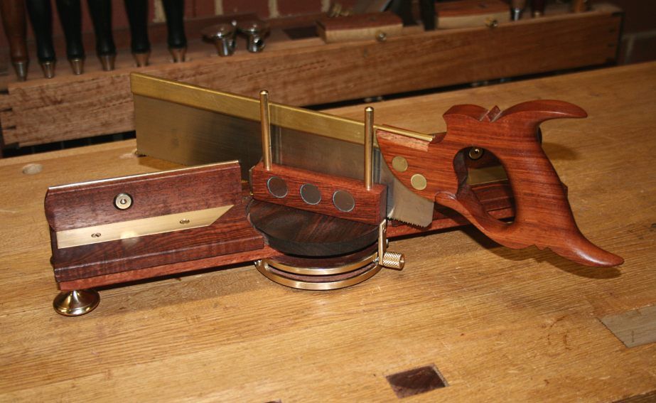
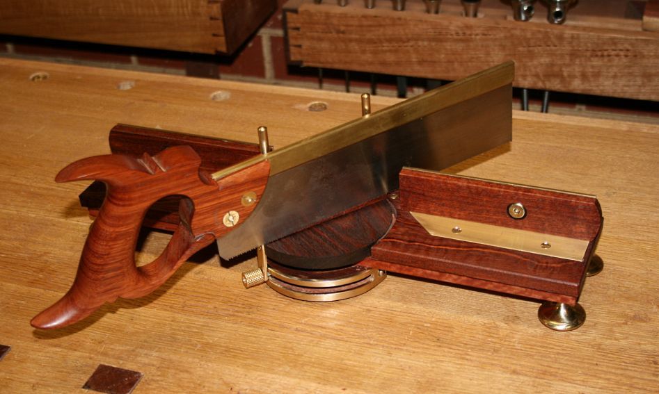
The mitrebox is Jarrah and brass, just under 17" in length, 4" deep, and 3 1/4" to the top of the fences. It is used with an 11" carcase saw I made 2 years ago. This has a 2 1/4" plate and is filed 14 ppi crosscut.
MB1_zps9d212136.jpg


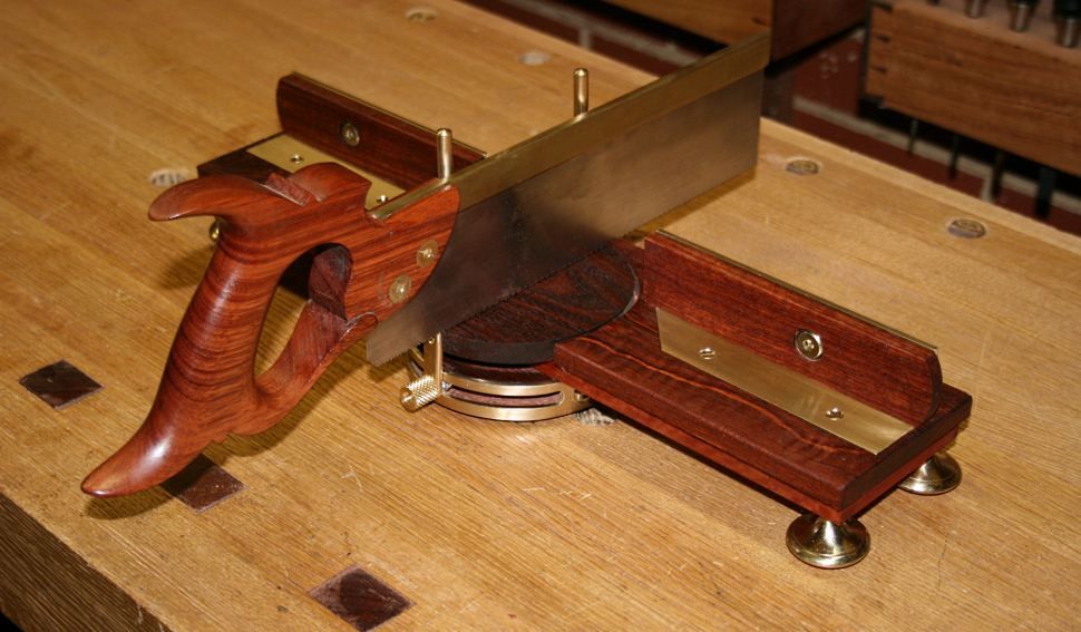
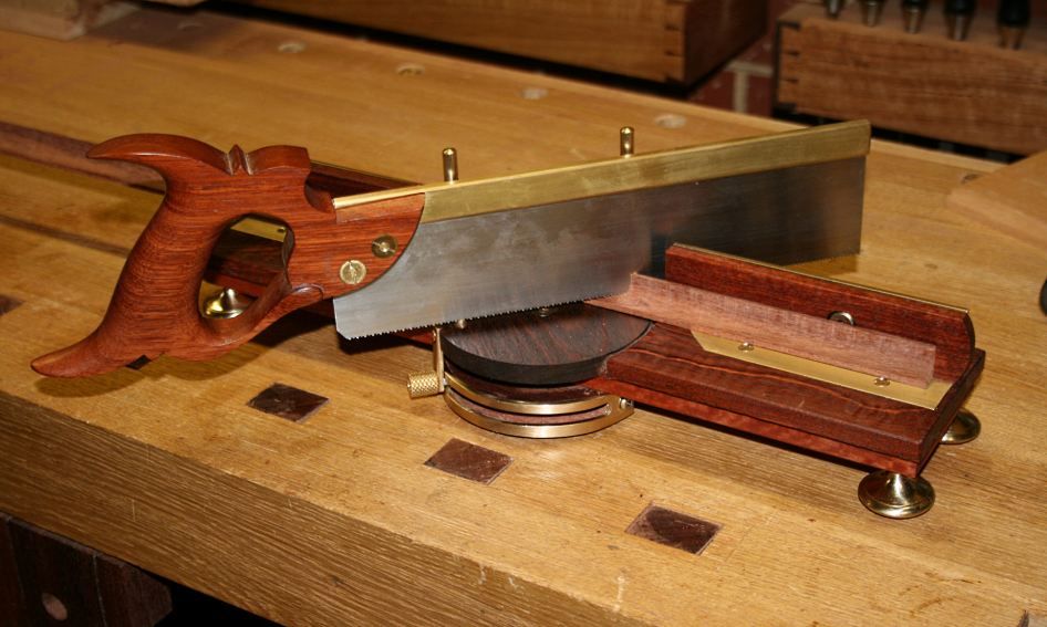
In order to make the depth as shallow as possible, the turntable (for the saw) needed to be small, and this led to placing it pivot point in the centre of the bed. To close up the gap in the fence that results from this, the fence contains a subfence that slides back-and-forth ...
MB3_zps43572d69.jpg


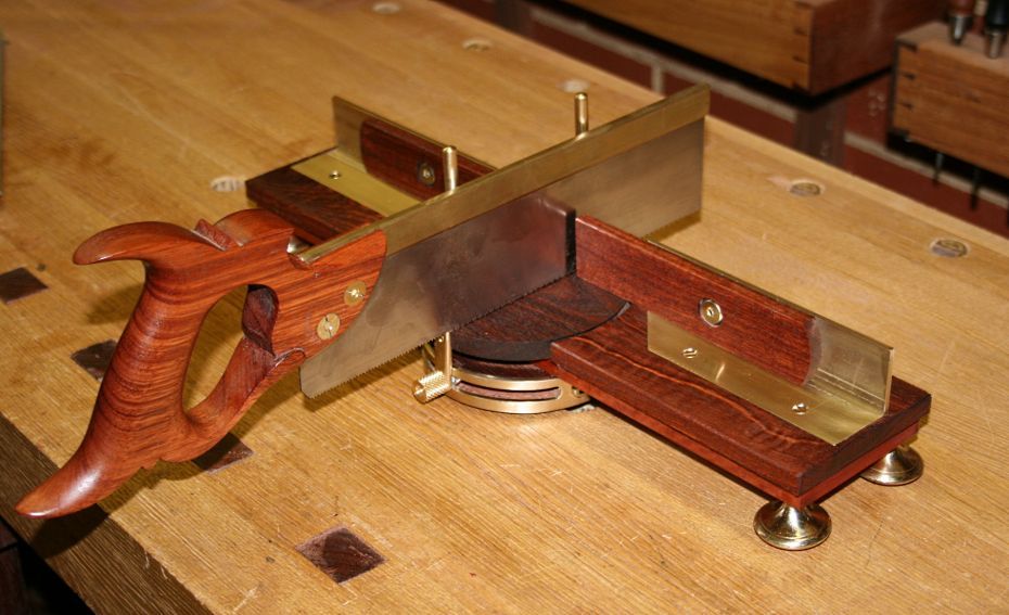
With the fences back, the mitrebox is optimised for mitres ...
MB2_zpsca4b134f.jpg


Here is the same moulding from the kist ....
MB8_zps5fe59c30.jpg


A comparison with a MF Acme 74A ...

MB9_zps558a0d92.jpg


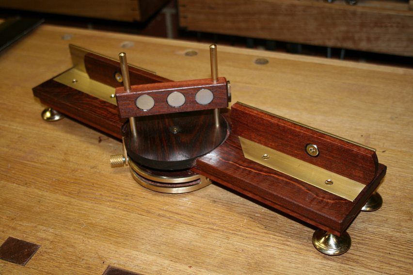
The heart of the saw-holding mechanism is a plate with rare earth magnets ...
MB10_zps26380dfd.jpg


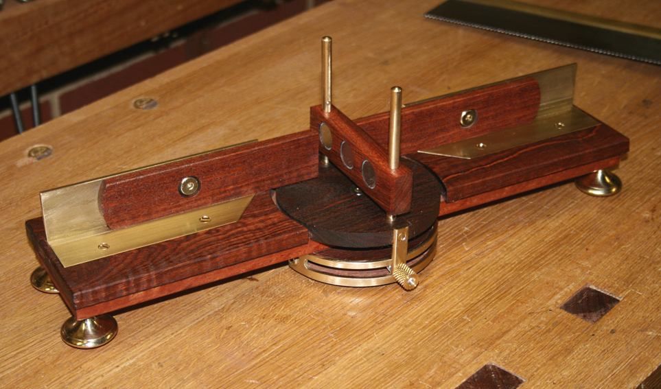
Another shot, as well as the angle locking mechanism ...
MB4_zps80e11953.jpg


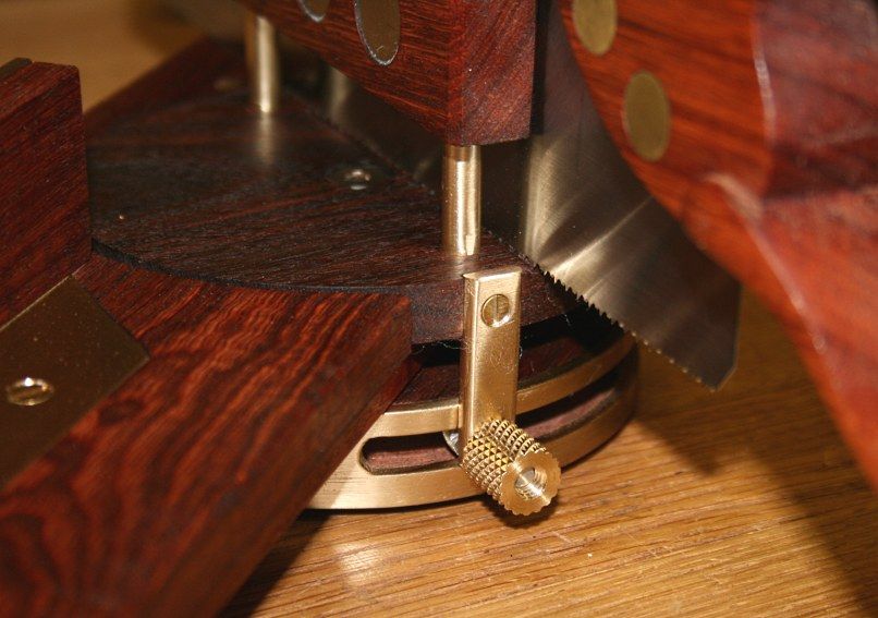
The locking mechanism is built on a morticed Jarrah disk ...
MB7_zps7c03cc63.jpg


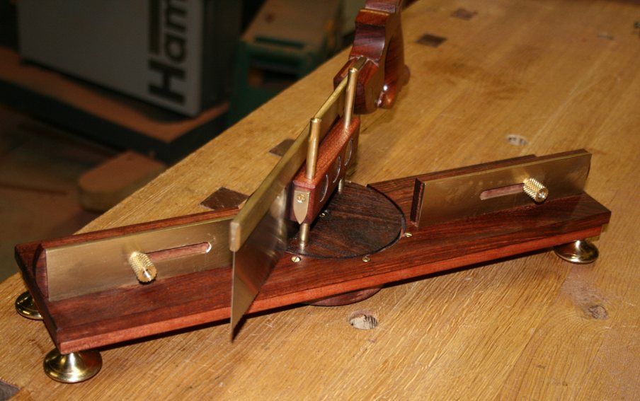
The fence is a 1 1/4" x 1 1/4" brass angle section, with Jarrah subfences. At the rear is a slide adjuster ...
MB5_zpsee0d0ed3.jpg


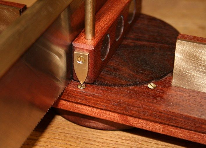
You can make out the angle settings. The fence is set up for quick adjustment to 45 degrees either way and 90 degrees. It has a variable range from about 40 degrees. The saw can be used on either side of the fence.

Here is a close up of the settings ...
MB6_zpsb8291f33.jpg


MB11_zps213ff8f8.jpg


Regards from Perth

Derek
 
With the exception of the feet, which are modified drawer handles, I built everything. Amazing what one can do with a Dremel and files!

The rotating Jarrah disk is actually two disks, one screwed to the base and the other pivots above it. The lower disk is morticed for the lock, and the upper disk hold the rods for the sliding blade holder. The brace facing strip started life as flat brass, which came under the knife of a Dremel wheel, and then bent around the disk. Tough work as all the brass is about 3mm thick.

The knurled locking nuts were purchased on eBay (UK) for the router plane I built some months ago ( http://www.inthewoodshop.com/ShopMadeTo ... Plane.html ).

It looks like I shall have to dissemble the mitrebox for photos as I have had several requests. Fortunately it is just screwed together.

Regards from Perth

Derek
 
With the exception of the feet, which are modified drawer handles, I built everything. Amazing what one can do with a Dremel and files!

The rotating Jarrah disk is actually two disks, one screwed to the base and the other pivots above it.

Beautiful work Derek - love the steampunk look. Overkill for actually cutting mitres, of course, but who cares about that?

I may have a helpful hint for the pivoting action. A while ago I bodged together a panohead for my camera (not a work of beauty...)

http://en.wikipedia.org/wiki/Panoramic_tripod_head

pano_head.jpg


The various pivoting motions weren't completely smooth. Here's the trick I found:

http://panotoolsng.586017.n4.nabble.com ... 88i20.html

another list":37o1yaaw said:
I have now greatly improved the motion on the yaw (vertical axis)
motion.

I simply put a washer (2" diameter) between the base plates
of the head.

The washer was cut from a 4 pt milk container, so for other
people in the UK, that's probably all you need to know.

For people outside the UK, I have looked up exactly what the
plastic is. Decoding the UK recycling symbol,
it's HDPE.

http://scifun.chem.wisc.edu/chemweek/po ... ymers.html

The resulting motion is really quite smooth and easy, and yet
doesn't move without significant force.

Not quite as good a motion as the focusing on a good lens,
but hell, it's much cheaper!!

BugBear

BugBear
 
Well if I had a tool that looked like that it would be on display in glass a cabinet in the lounge, not hidden away in the workshop.
 
bugbear":2m6gtsc6 said:
With the exception of the feet, which are modified drawer handles, I built everything. Amazing what one can do with a Dremel and files!

The rotating Jarrah disk is actually two disks, one screwed to the base and the other pivots above it.

Beautiful work Derek - love the steampunk look. Overkill for actually cutting mitres, of course, but who cares about that?
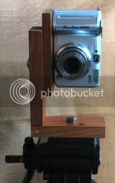
I may have a helpful hint for the pivoting action. A while ago I bodged together a panohead for my camera (not a work of beauty...)

http://en.wikipedia.org/wiki/Panoramic_tripod_head

pano_head.jpg


The various pivoting motions weren't completely smooth. Here's the trick I found:

http://panotoolsng.586017.n4.nabble.com ... 88i20.html

another list":2m6gtsc6 said:
I have now greatly improved the motion on the yaw (vertical axis)
motion.

I simply put a washer (2" diameter) between the base plates
of the head.

The washer was cut from a 4 pt milk container, so for other
people in the UK, that's probably all you need to know.

For people outside the UK, I have looked up exactly what the
plastic is. Decoding the UK recycling symbol,
it's HDPE.

http://scifun.chem.wisc.edu/chemweek/po ... ymers.html

The resulting motion is really quite smooth and easy, and yet
doesn't move without significant force.

Not quite as good a motion as the focusing on a good lens,
but hell, it's much cheaper!!

BugBear

BugBear
I've seen a post on www.hackaday.com about using a rubber band to to move a tripod head smoothly, incidentally, I believe the clutch-plate in one of my telescope mounts uses hdpe or something very similar on the alt (up/down) axis, not entirely sure what the purpose is as slippage is a major pita when you're driving a mount with motors, so I'm guessing it's a safety feature to allow the thing to slip and not thrash the motors if it's overloaded or if the scope is prevented from moving by something.
 
And that's a fantastic looking mitre box, I was just thinking I might like to make a 'wedge' for my telescope in a steam punk style, although I'm not sure if it would look right with all the technology hanging off it and whether it would be that useful as I only tend to look at the telescope when it's dark and really only look through it rather than at it so I may just go for plywood instead.
 
I think it is an object of beauty and would love to own one or even the ability to make one, Well done
 
Thats a little beauty Derek !!! Well done ;) :mrgreen:

Sent from my GT-I9300
 
Reggie":3ay6qzm4 said:
"Find a rubber band and start to pan..." http://life.hackaday.com/smooth-camera-operator/

Ah - The band provides a converter from hand movement to torque - the smoothness of the resulting movement is heavily reliant on the tripod pivot being nicely made, which the cheaper ones aren't! If there's a stiff point in the pivoting, the rubber band will make the results worse.

BugBear
 
Another wonderful tool Derek, your tool cabinet must look like an escapee from a high end tool store.
A question if I may. I see, from the images, that the magnets are set sub-flush in their mount. Is this to reduce drag on the saw blade?
I particularly like the 'double-sided' nature of the tool. It must help a lot to be able to see clearly just what is going on.
Great stuff.
xy
 
Back
Top