MichaelChou
Established Member
This is really helpful. Thanks for sharing.


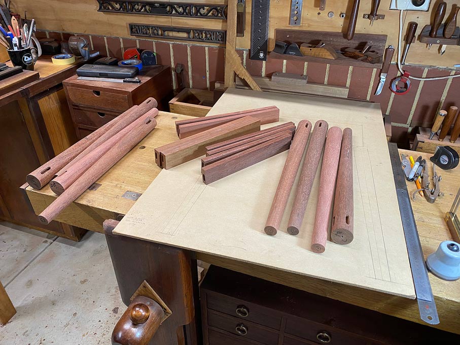
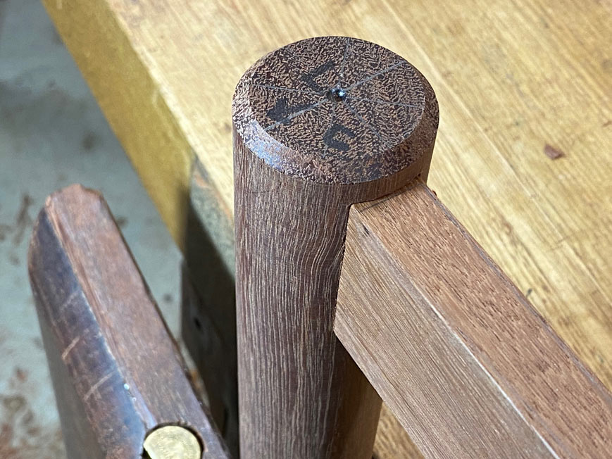
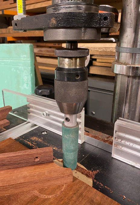
Interesting method of turning the tapered legs.
IMO, you made much more work for yourself but you got the results you wanted.
I also don't usually see turnings with the larger diameter at the tailstock end, this is opposite of what most people do. A template or story stick is often enough to mark diameters at intervals along the turning and connect the sections.
Admin at:
(The Woodturning Forum - Woodturner's Resource - Index)
Hi DerekSkyhooks
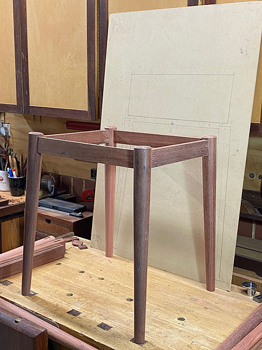
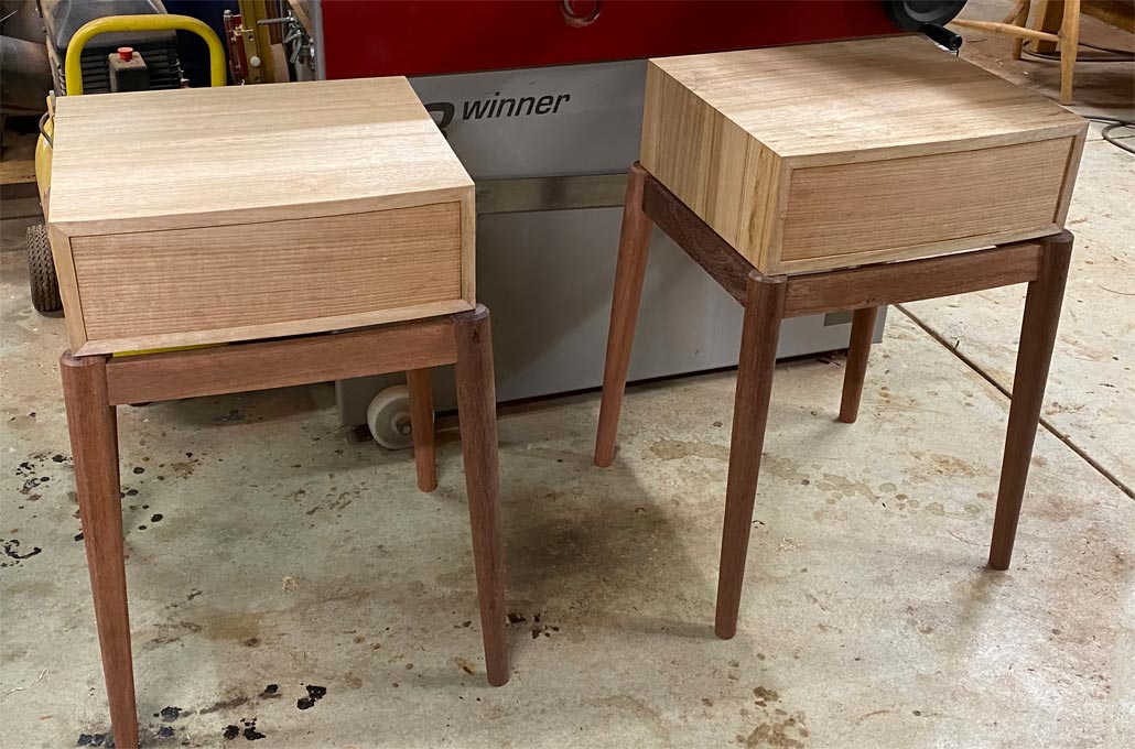
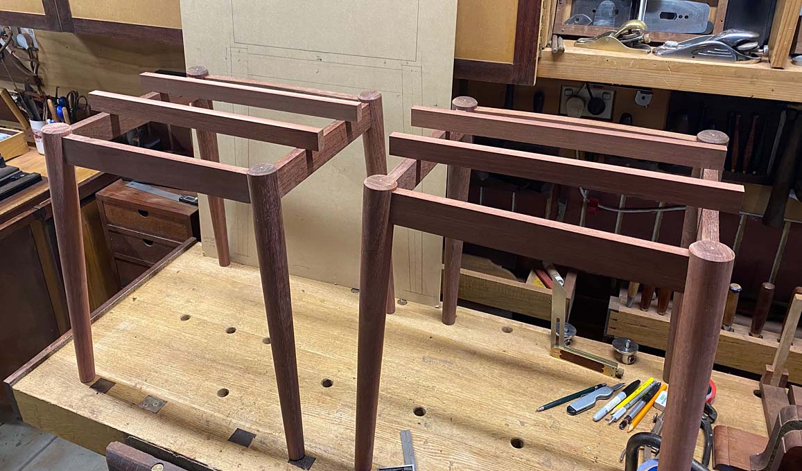
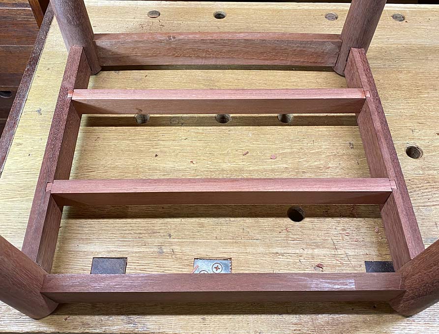
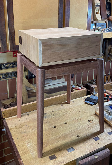
Last time the nightstand build ended with a mock up of one nightstand ..
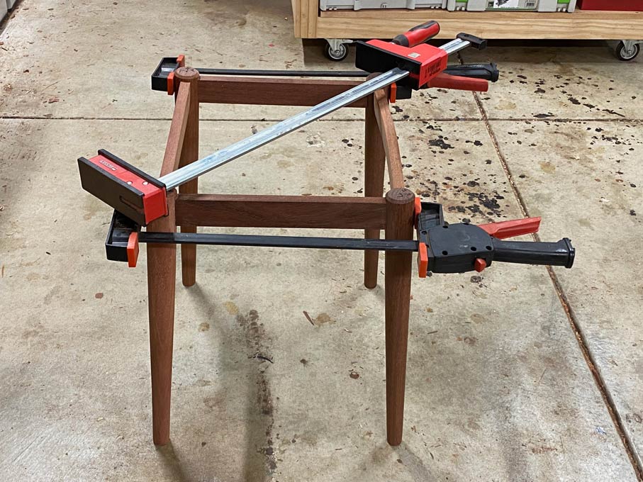
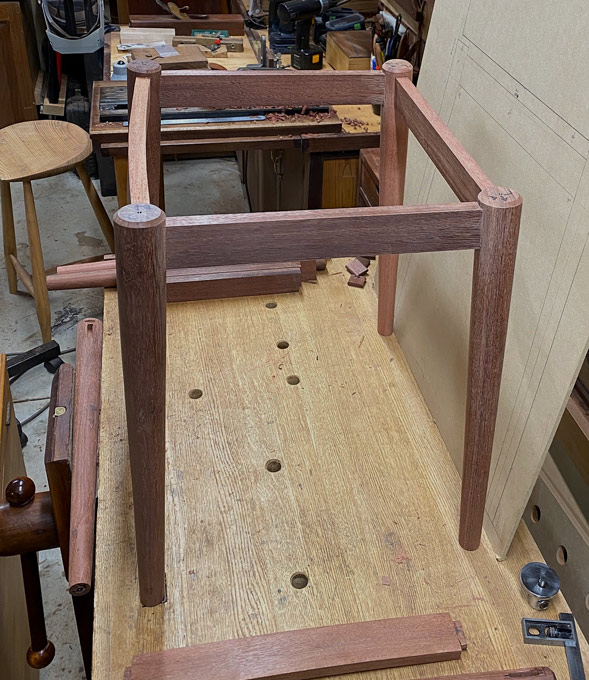
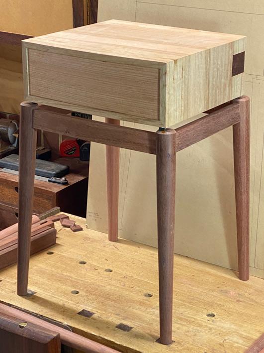
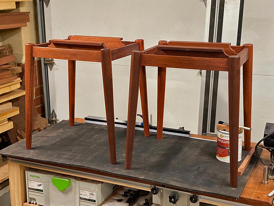
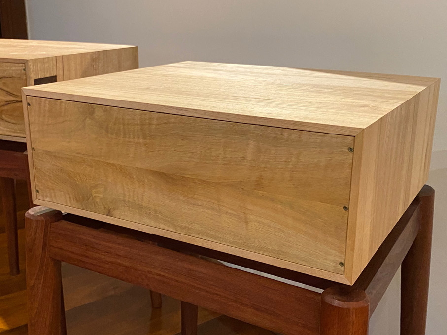
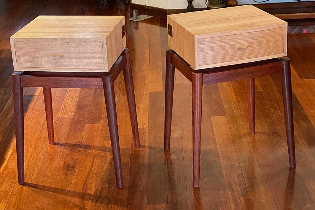
Here steel nuts were used to lift the cabinet off the base. This weekend I completed the second base. Here are the two with the cabinets resting on the bases ...
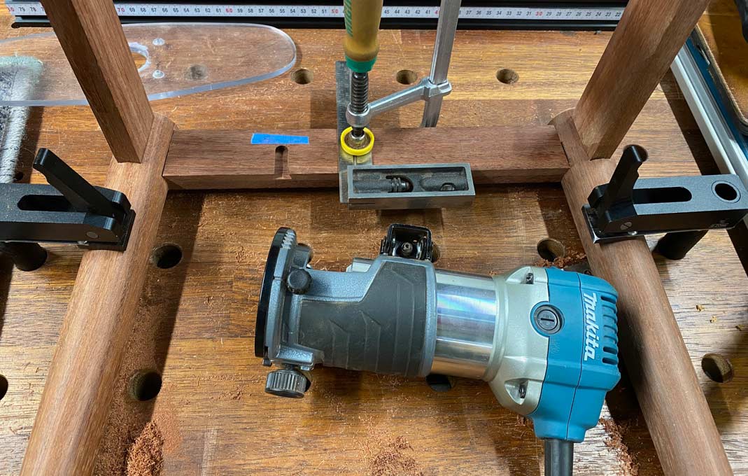
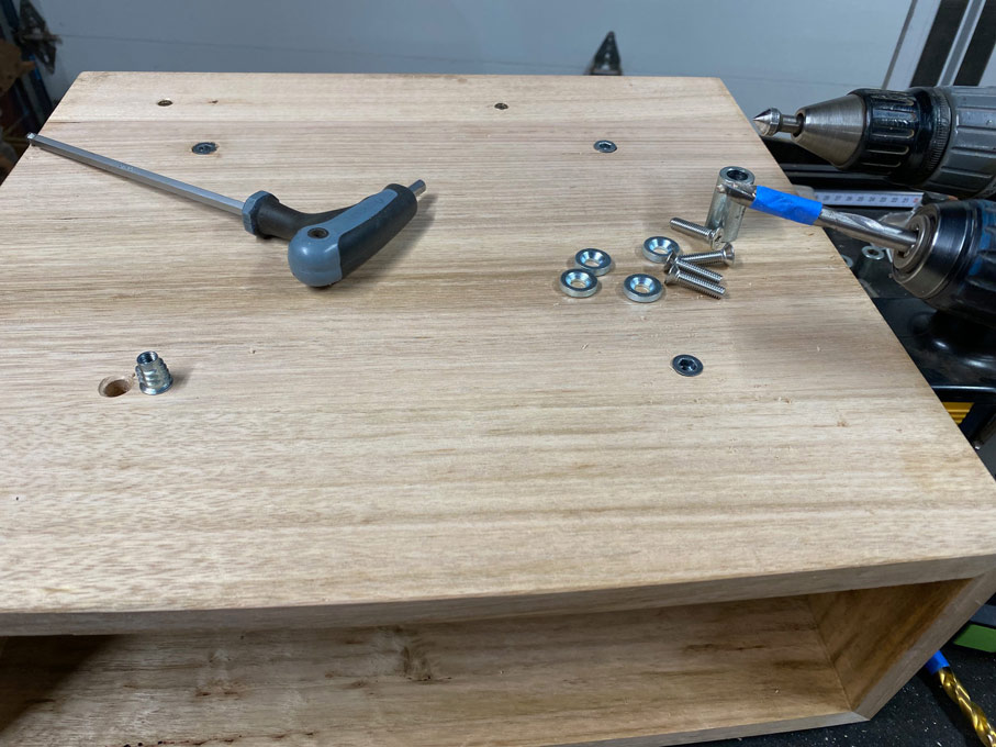
I had been planning to construct the floating appearance by using a slight variation of this construction ...
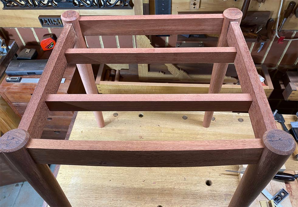
... but the example with the nuts had me thinking if there was another way, one less observable from the side.
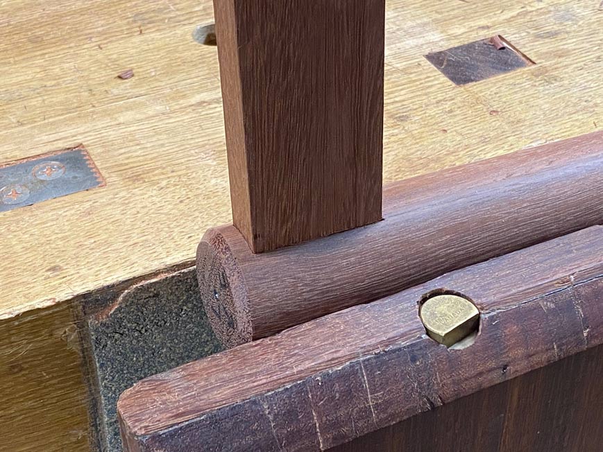
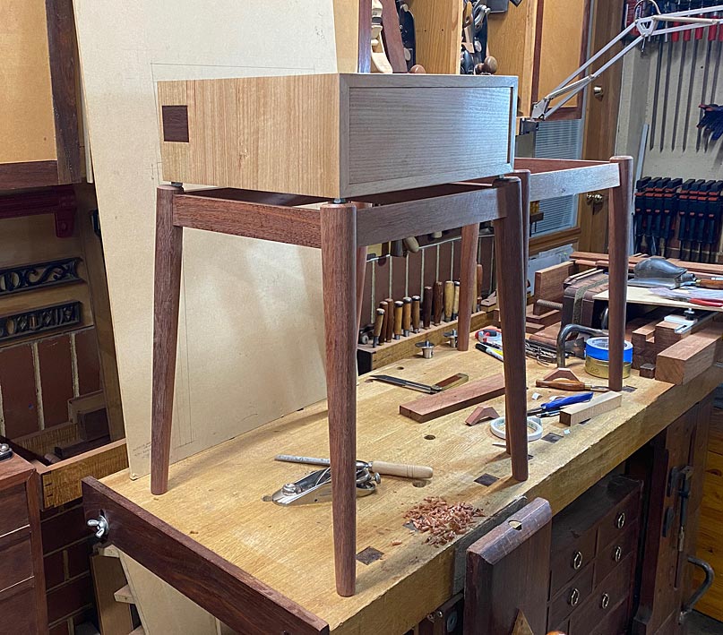
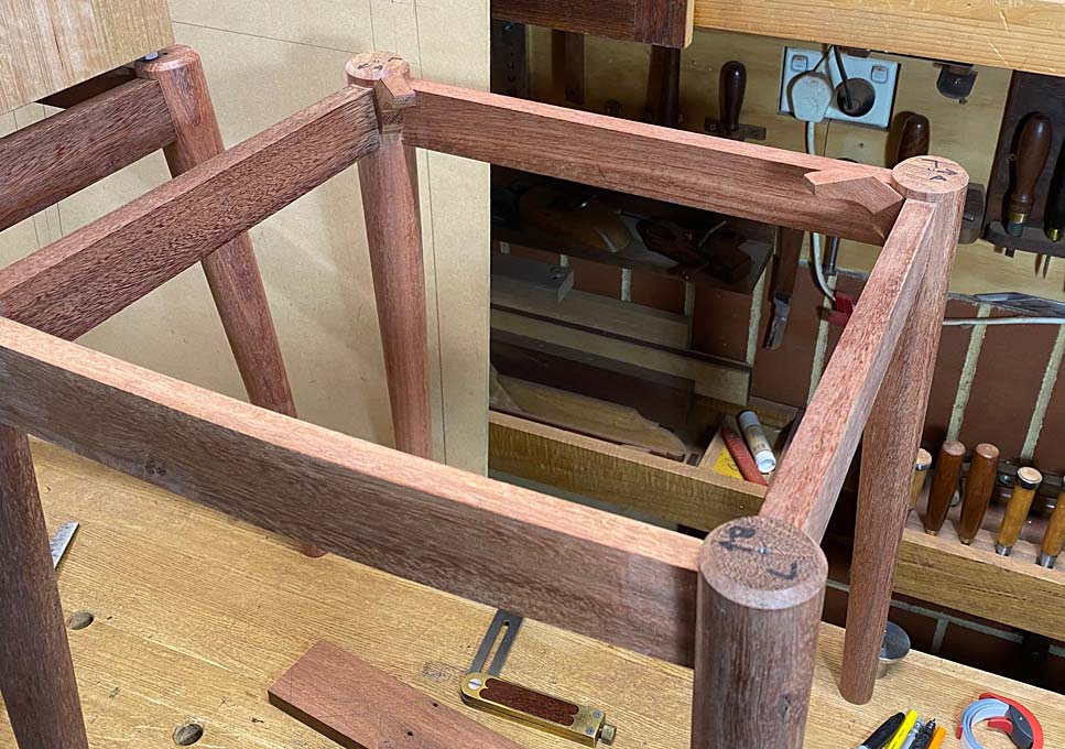
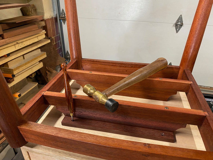
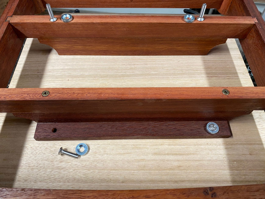
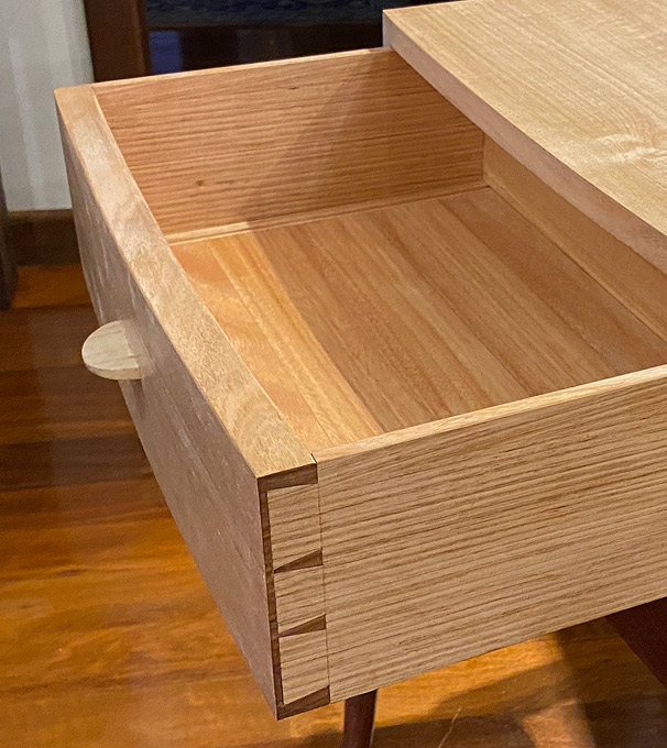
Here is a mock up again, taken today ...
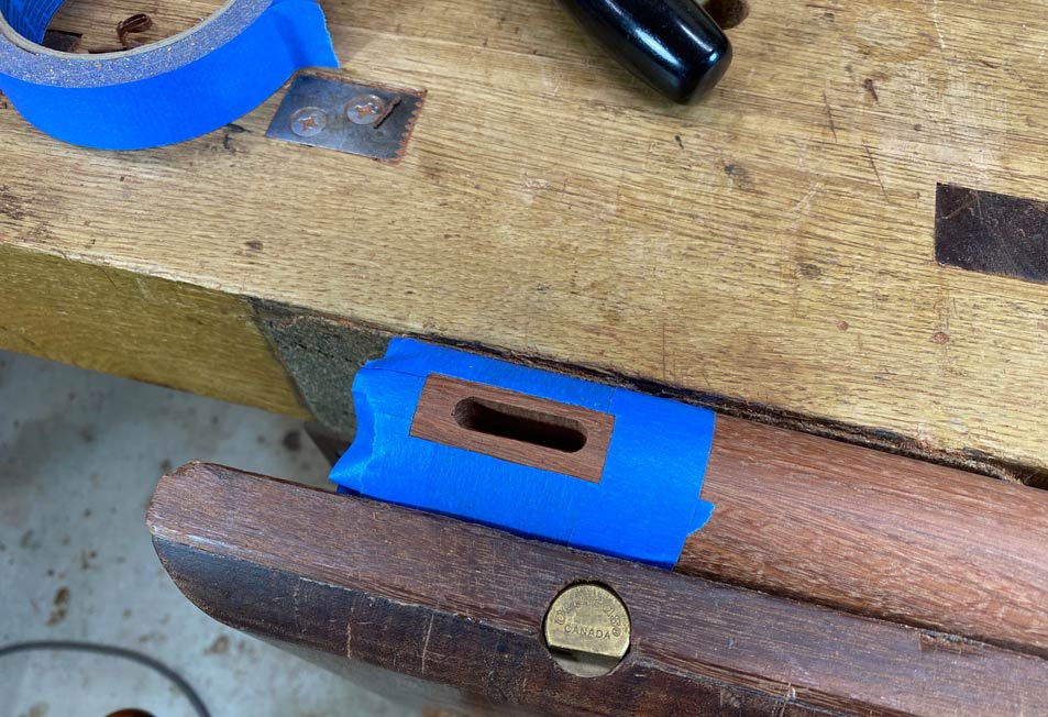
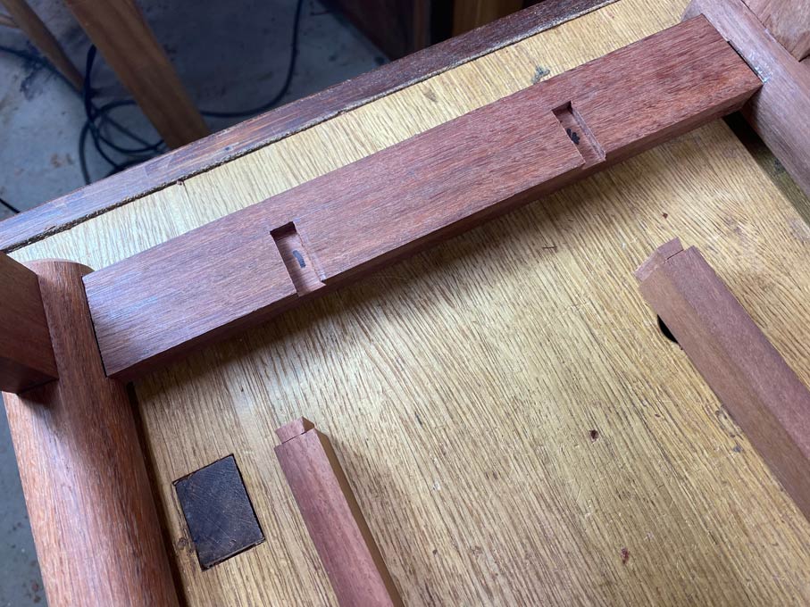
I came up with this linkage, and what I am after is some opinion as to how secure you imagine it will be.
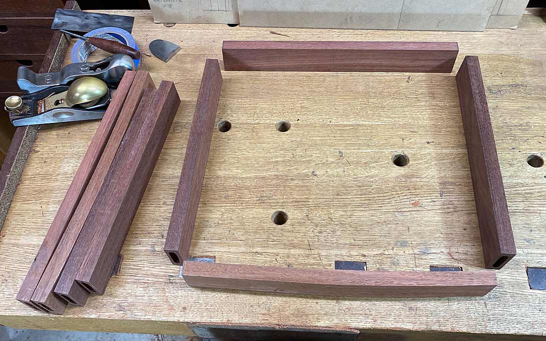
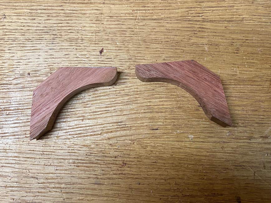
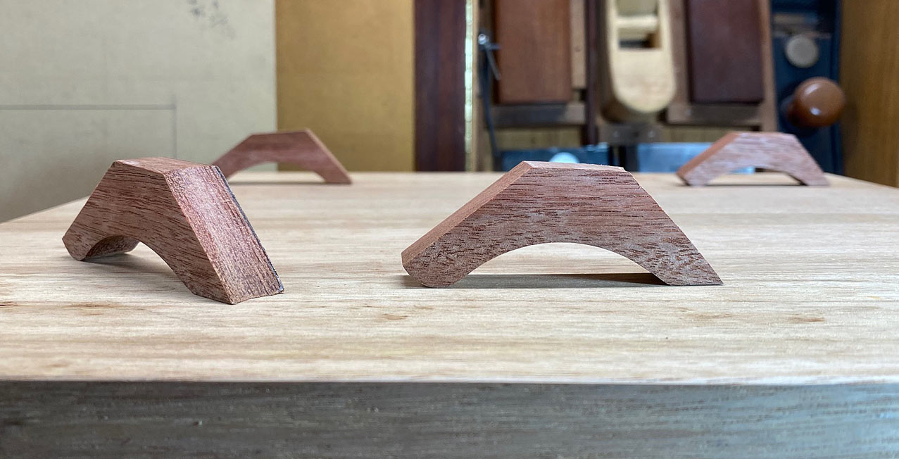
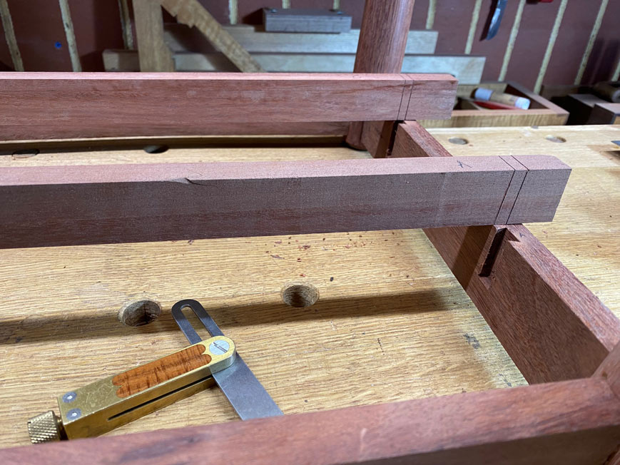
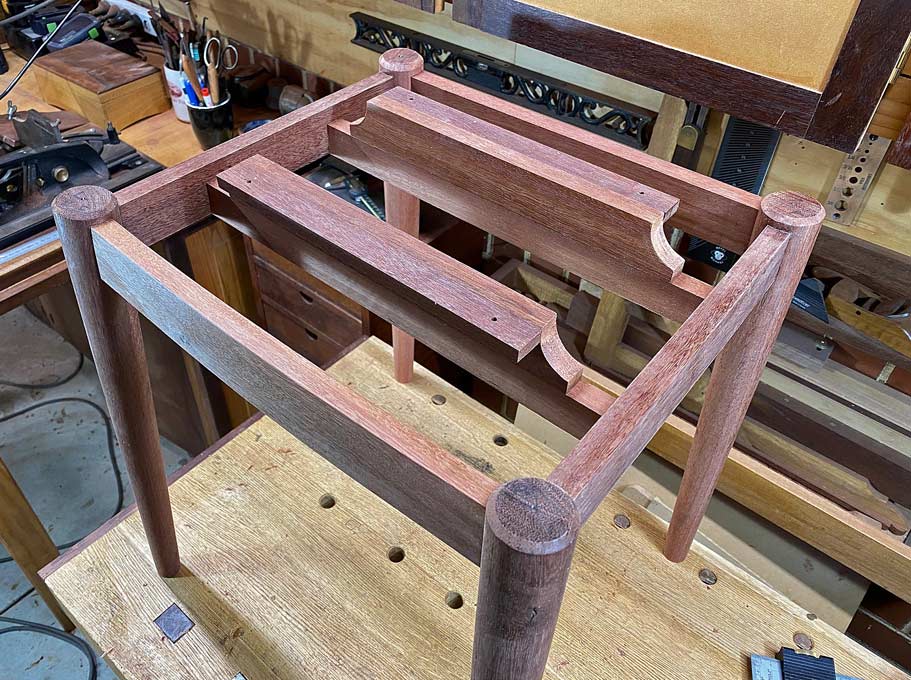
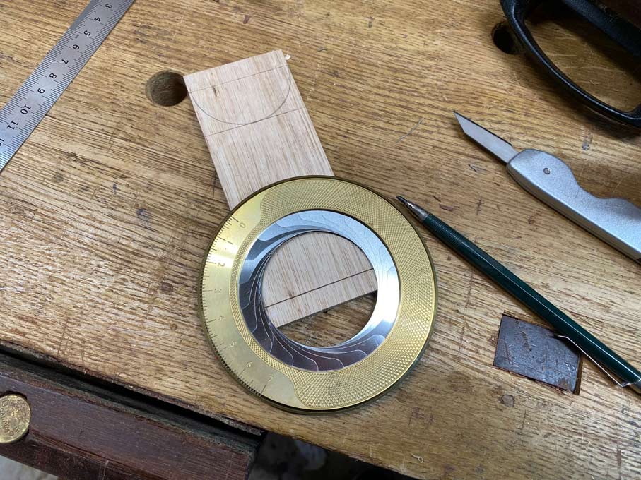
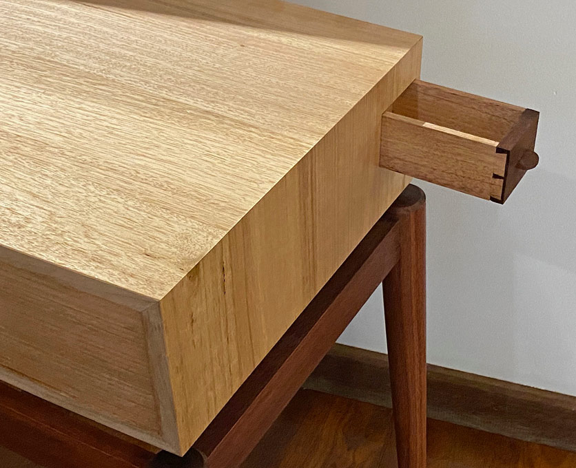
These simply began as Jarrah triangles, and were shaped to reduce unnecessary bulk (which might be visible). All legs are 10mm thick x 18mm wide ...
For greatest strength, the grain runs across the bracket.
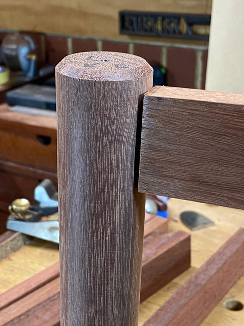
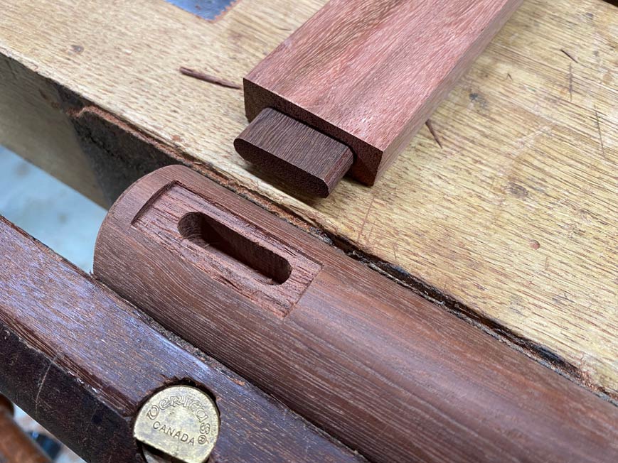
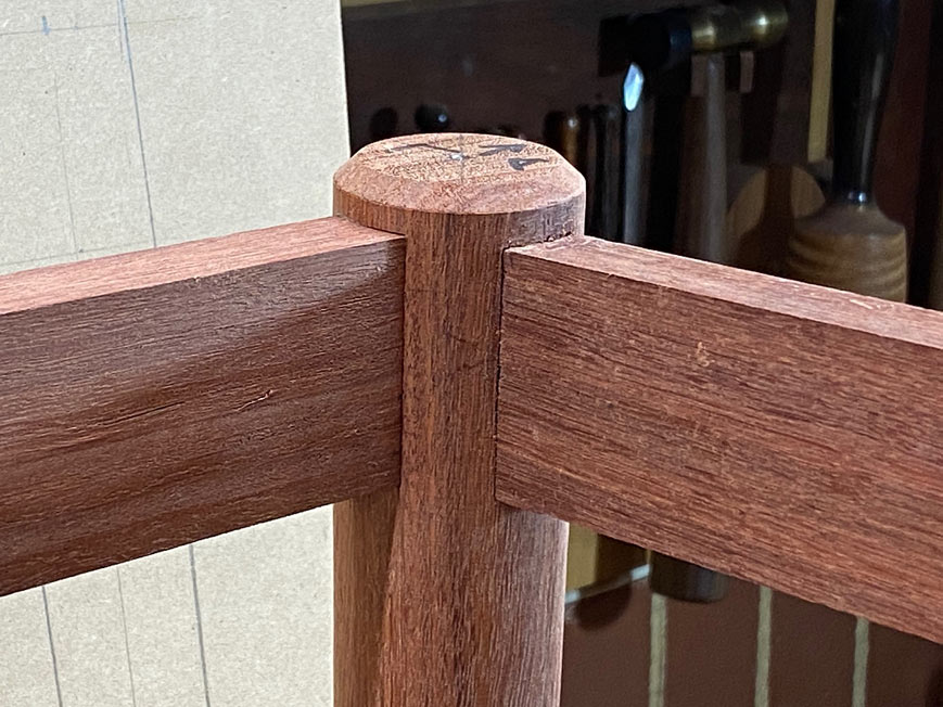
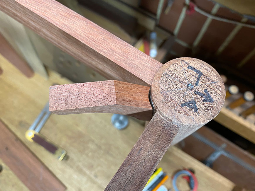
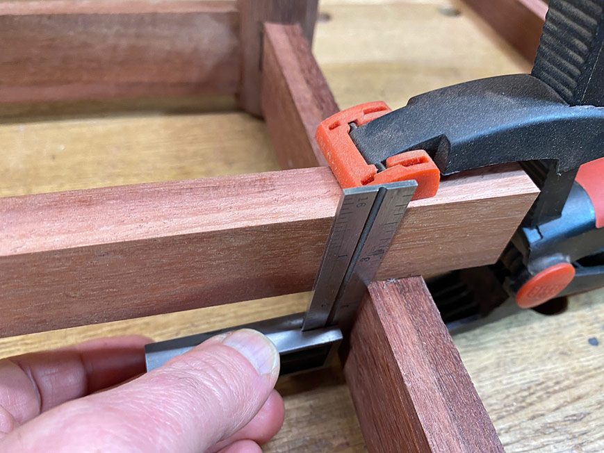
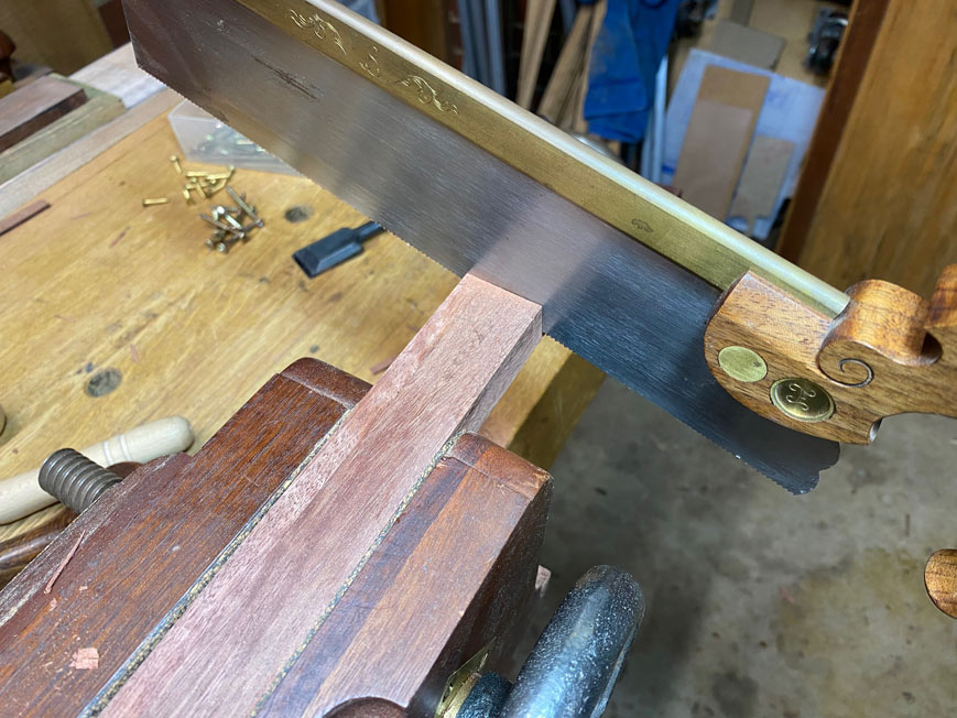
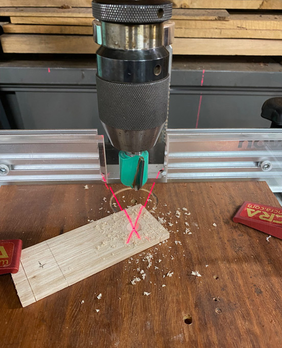
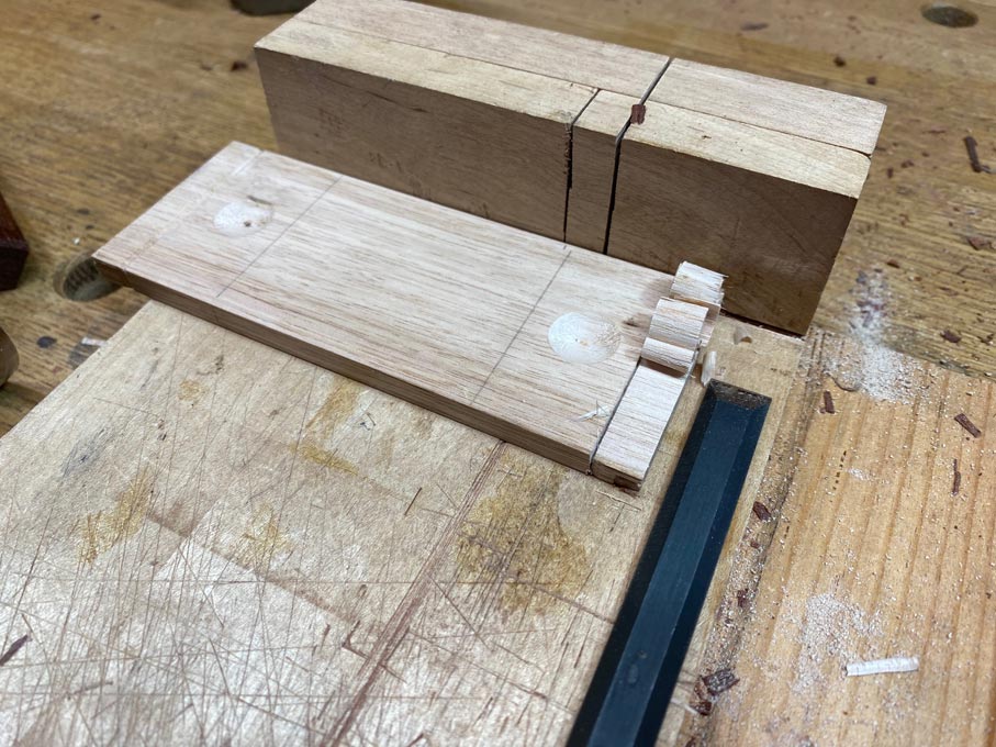
The one side was coped to fit flush with the round leg ...
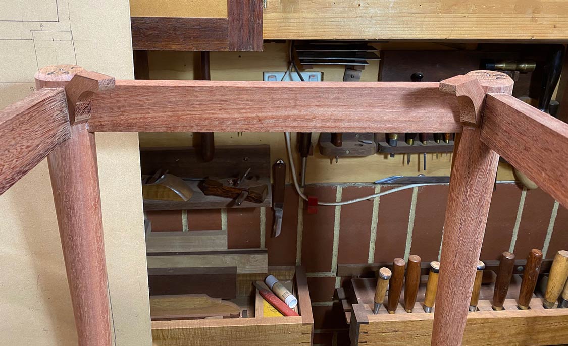
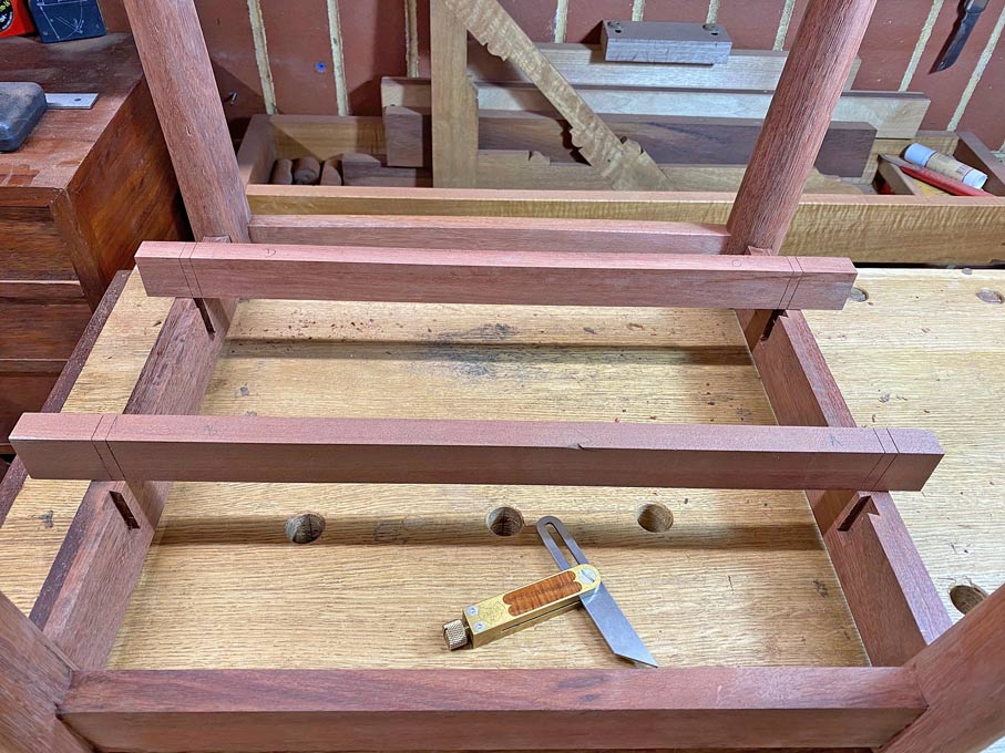
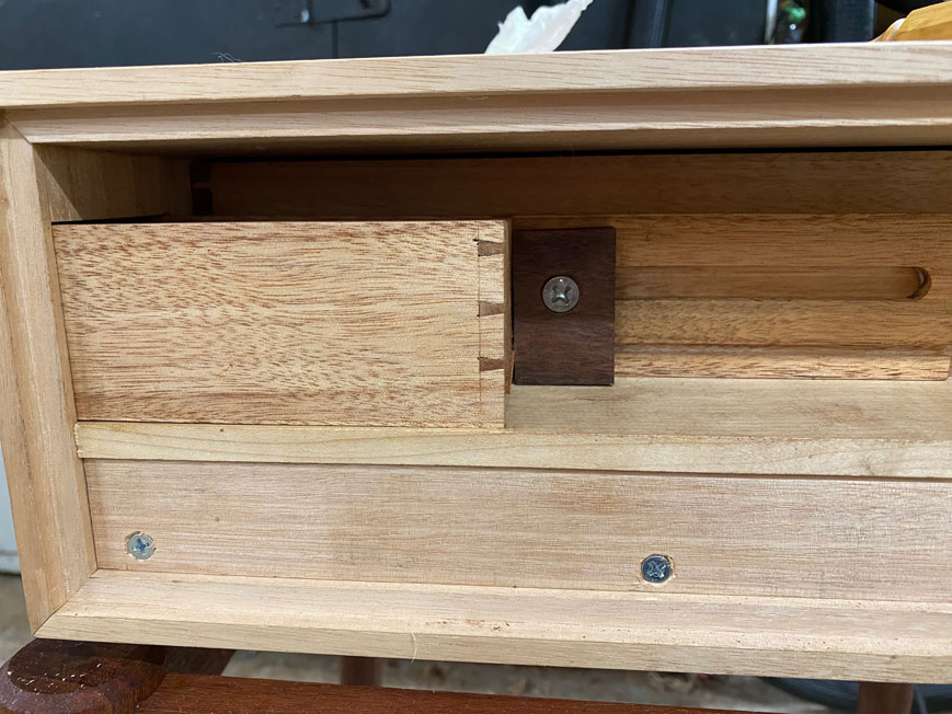
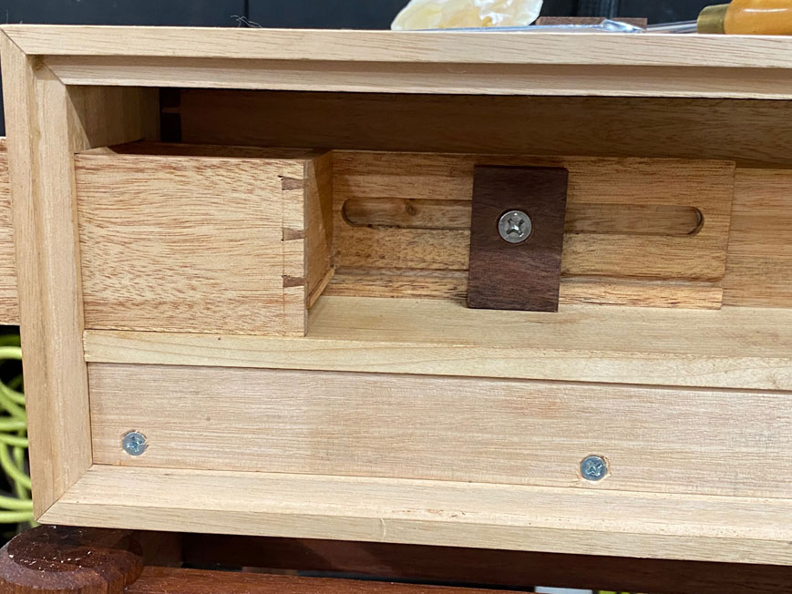
This is how it is intended to be fitted ...
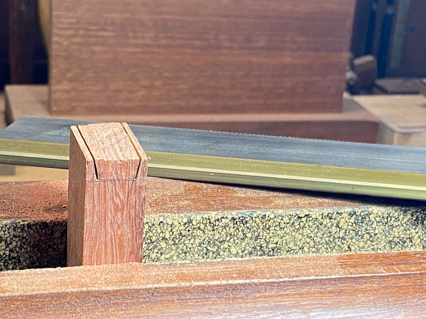
Here is the mating of the coped inside with the outside of the round leg ...
The plan is to glue and screw the coped side. The glue joint should create a strong connection, and a screw will just provide extra support. The cabinets will be screwed to the top of the bracket.
Opinions and ideas?
Regards from Perth
Derek


Enter your email address to join: