RobertMP
Established Member
Thought it was about time I started a WIP thread. Might help get me moving a bit faster. At current speed I might just make it by the end of the allowed time.. might ")
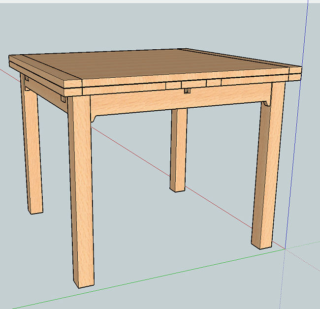
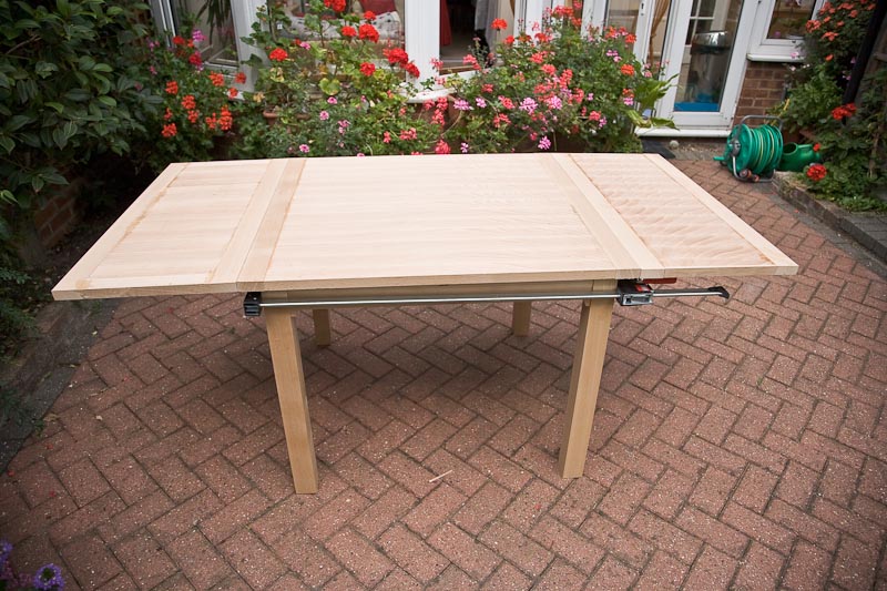
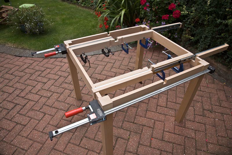
I've spent a fair bit of time on the completely unproven design in this thread - https://www.ukworkshop.co.uk/forums/view ... hp?t=32615 . Whether it actually works is yet to be seen so it may yet be a fixed table project!
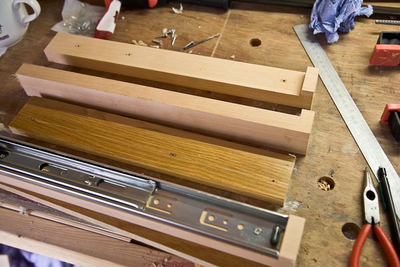
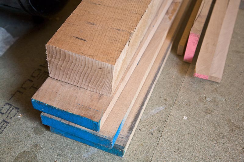
I went to my usual timber merchants and managed to catch them almost completely out of Beech They has some heavy stuff that was just over 4" by 3" in section and just 3 planks of 1". With the odd left over piece I still have it should be enough. It also meant the 60mm sq legs could be solid instead of glued from thinner stock.
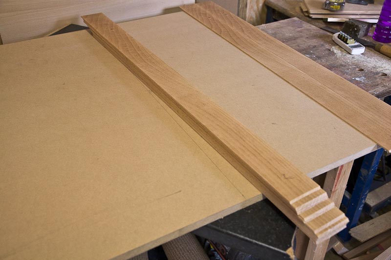
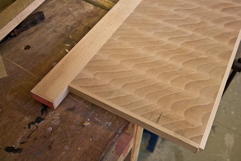
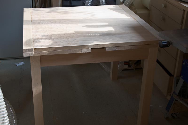
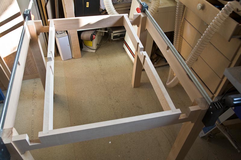
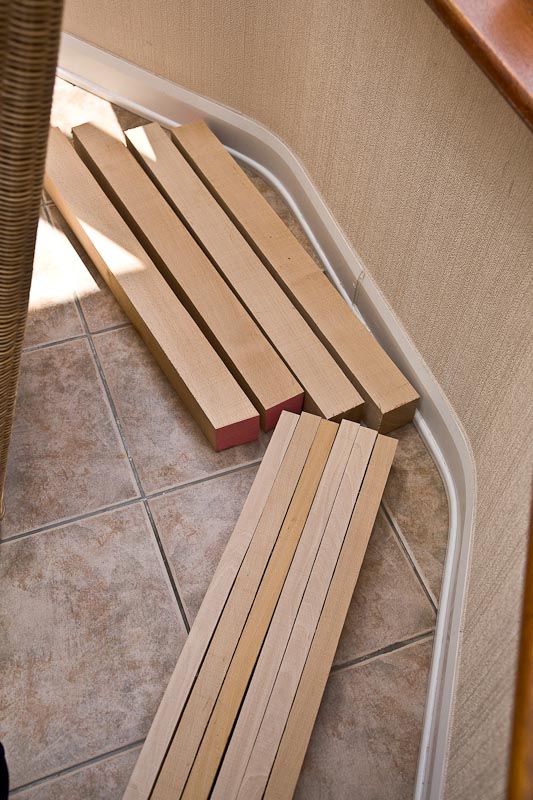
So I cut the table legs and the breadboard ends and have left them to cook in the conservatory where the table will live.
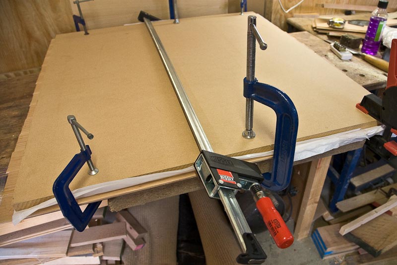
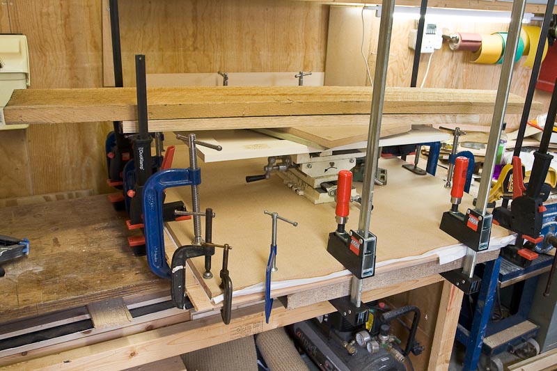
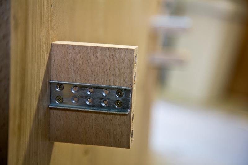
The items this is to match all have breadboard ends. This will too but I want to fake it with an MDF core to avoid the movement problems.
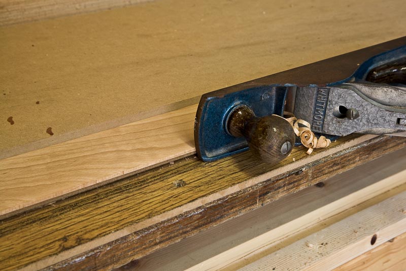
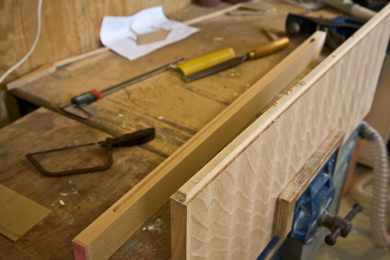
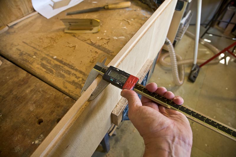
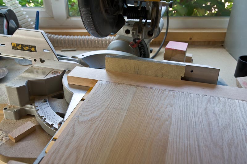
Might give a bit of a strip wood effect to the finished table but as cutting the 3" side was easier i decided to use the smaller face for veneers. I planed the face then cut it off.
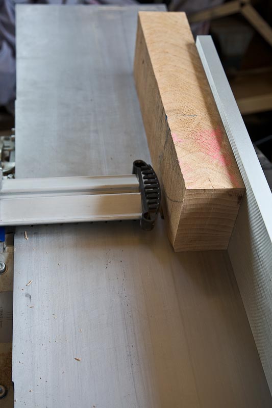
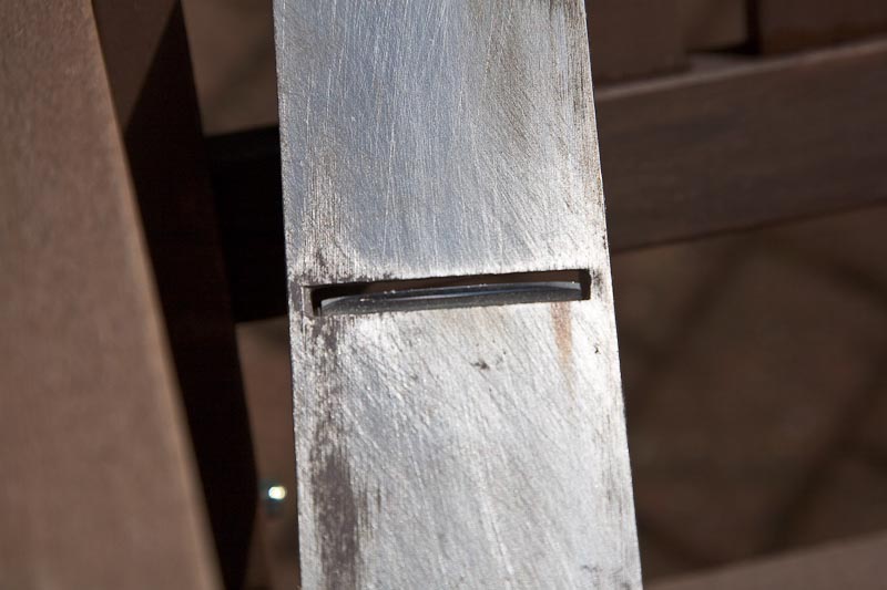
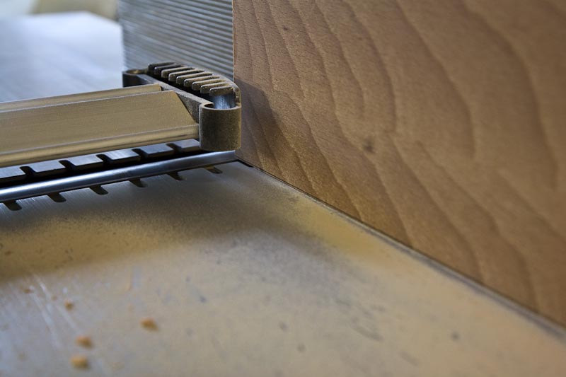
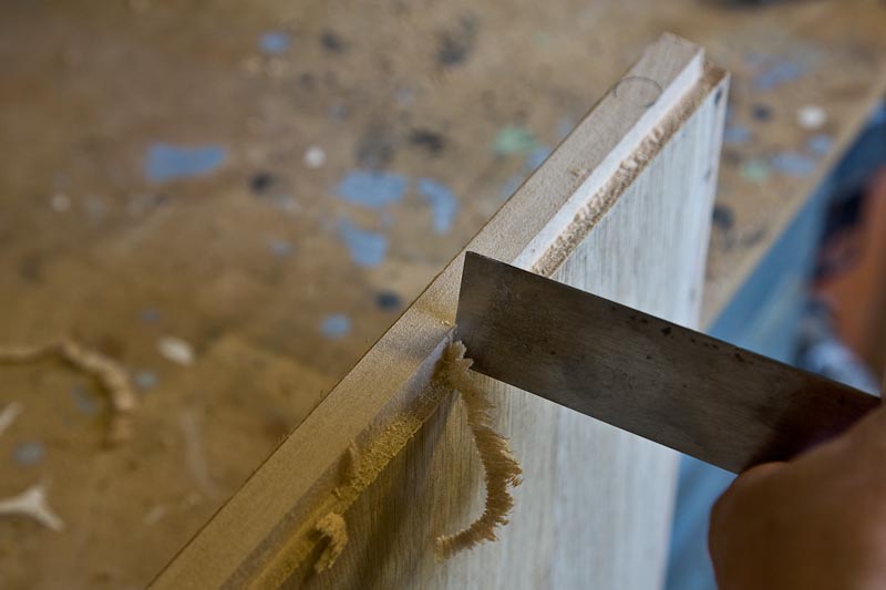
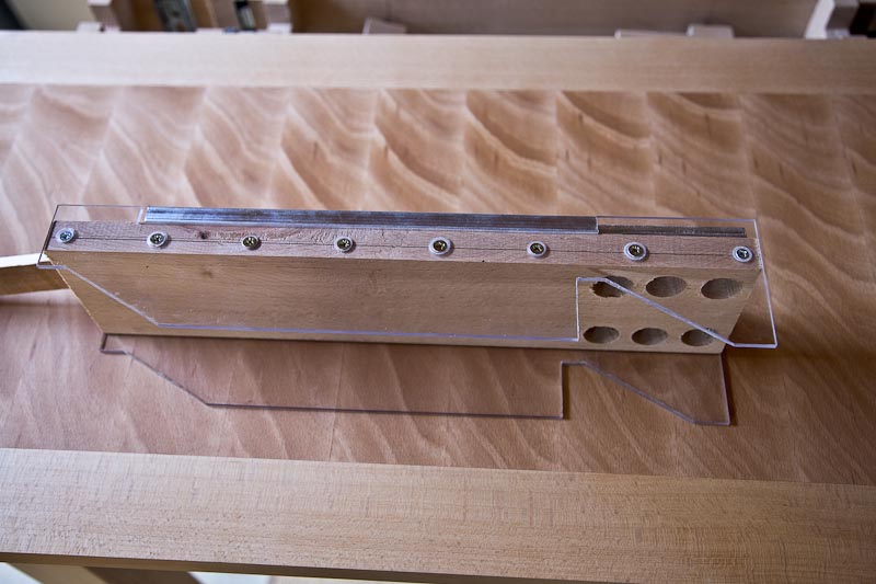
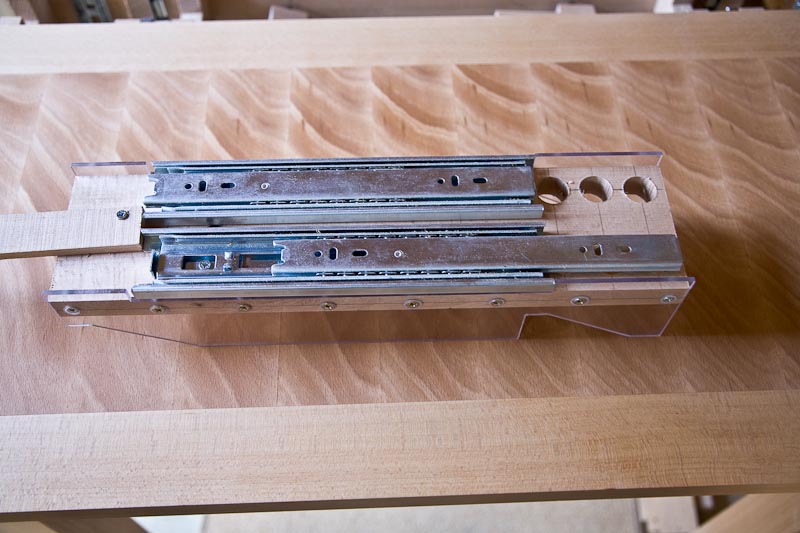
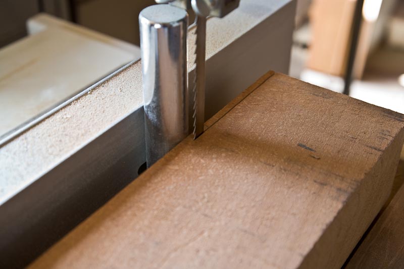
The resawing guide on the bandsaw fence. There is a small block of oak laying in front of the resaw thing to help me judge feeding it through straight. Don't like seeing all that blade so did all this with great respect!
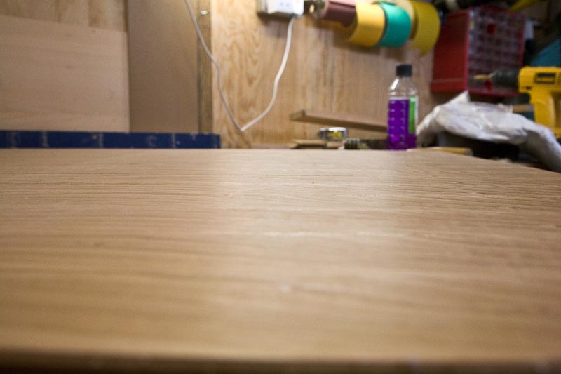
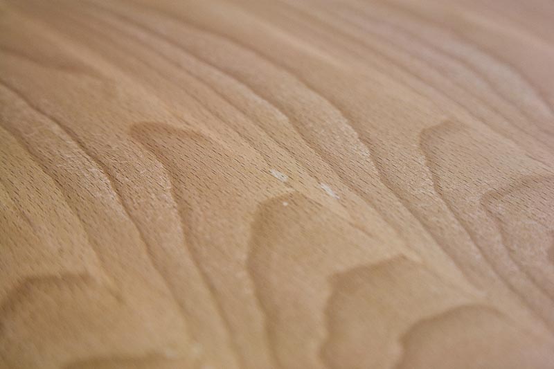
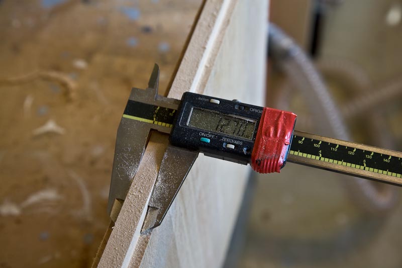
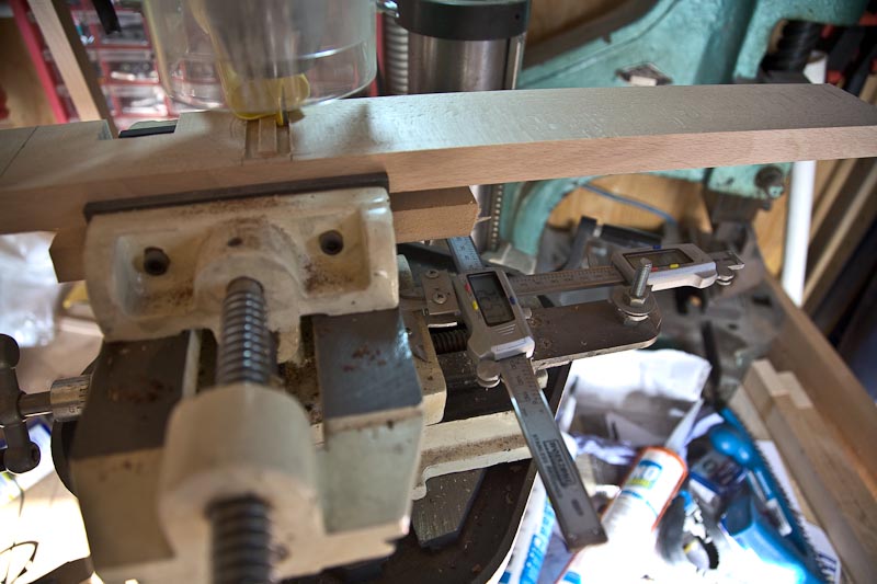
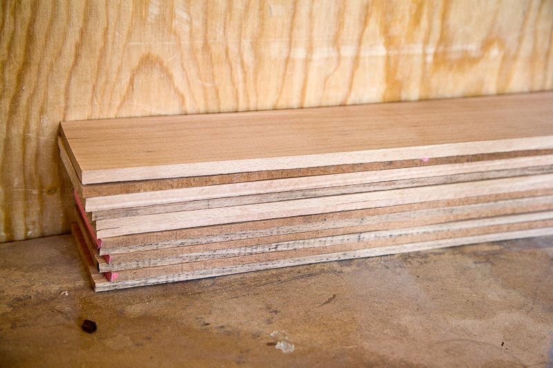
Strips have one smooth face and one sawn. they are not consistent enough to use as they are plus they are 5mm odd thick and i want 3mm
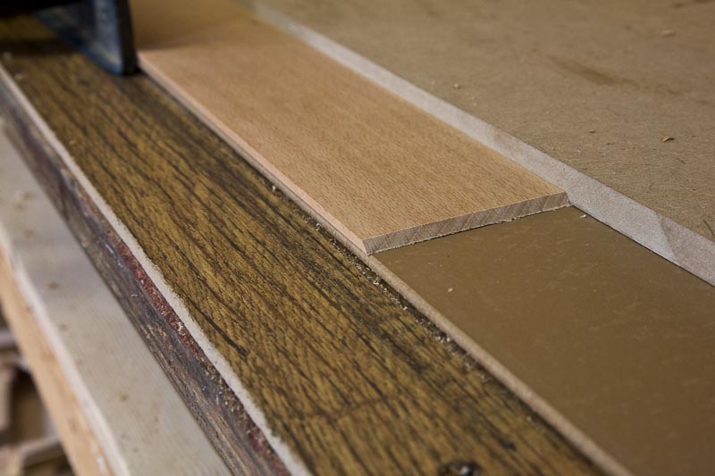
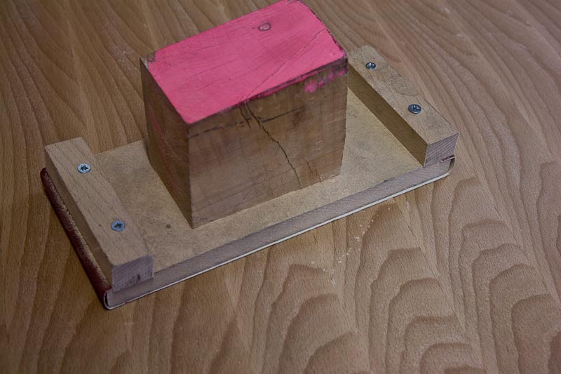
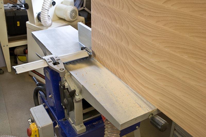
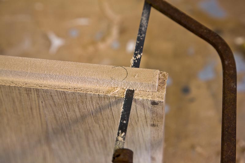
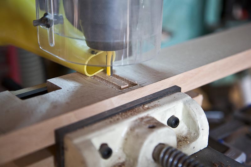
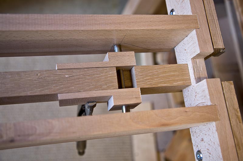
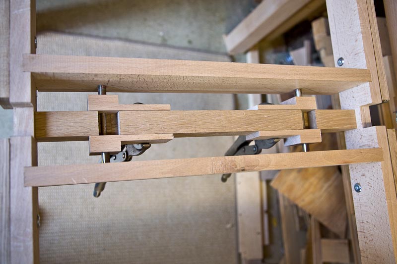
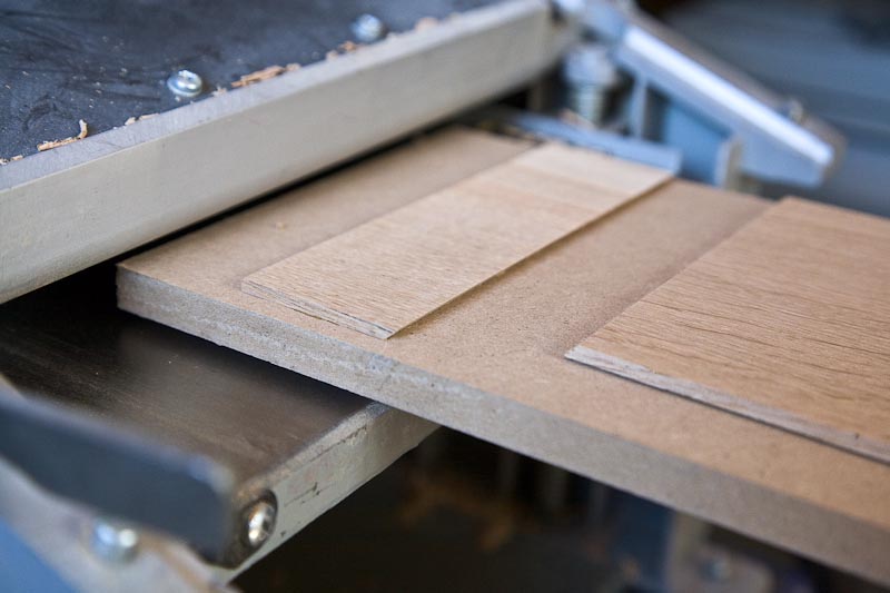
As the thicknesser cannot do 3mm i made a sled with a bit of 12mm MDF. I was worried about the thin leading edge as it hit the blade so i super glued a strip across with a 45 deg cut. All the strips have a matching cut to retain the leading edge. Worked well so far.
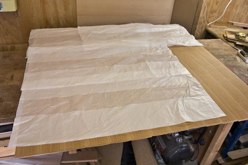
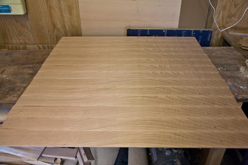
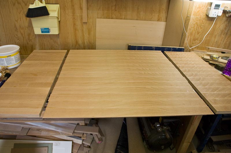
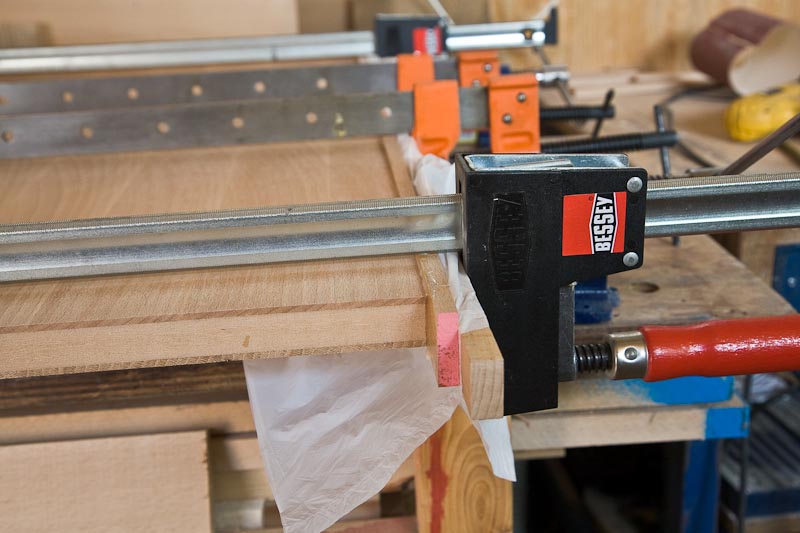
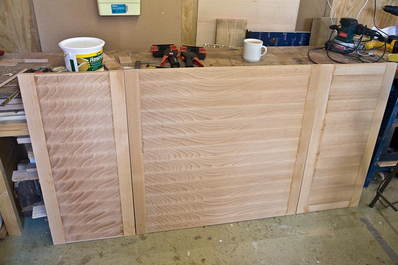
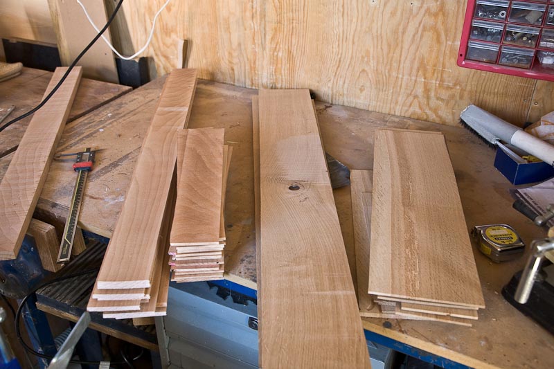
Beech for the tops on the left. Oak that will not be seen for the underside on the right. It is taking ages to thickness this lot! One more mm to come off yet.
Need to go and get a sheet of 18mm MDF for the core soon. Then the fun will really start when I have to face up to glueing this lot on!
I've spent a fair bit of time on the completely unproven design in this thread - https://www.ukworkshop.co.uk/forums/view ... hp?t=32615 . Whether it actually works is yet to be seen so it may yet be a fixed table project!
I went to my usual timber merchants and managed to catch them almost completely out of Beech
They has some heavy stuff that was just over 4" by 3" in section and just 3 planks of 1". With the odd left over piece I still have it should be enough. It also meant the 60mm sq legs could be solid instead of glued from thinner stock.
So I cut the table legs and the breadboard ends and have left them to cook in the conservatory where the table will live.
The items this is to match all have breadboard ends. This will too but I want to fake it with an MDF core to avoid the movement problems.
Might give a bit of a strip wood effect to the finished table but as cutting the 3" side was easier i decided to use the smaller face for veneers. I planed the face then cut it off.
The resawing guide on the bandsaw fence. There is a small block of oak laying in front of the resaw thing to help me judge feeding it through straight. Don't like seeing all that blade so did all this with great respect!
Strips have one smooth face and one sawn. they are not consistent enough to use as they are plus they are 5mm odd thick and i want 3mm
As the thicknesser cannot do 3mm i made a sled with a bit of 12mm MDF. I was worried about the thin leading edge as it hit the blade so i super glued a strip across with a 45 deg cut. All the strips have a matching cut to retain the leading edge. Worked well so far.
Beech for the tops on the left. Oak that will not be seen for the underside on the right. It is taking ages to thickness this lot! One more mm to come off yet.
Need to go and get a sheet of 18mm MDF for the core soon. Then the fun will really start when I have to face up to glueing this lot on!