Position of Router Plate and the Mitre track on a MFT Router Table

UKworkshop.co.uk

Help Support UKworkshop.co.uk:

This site may earn a commission from merchant affiliate links, including eBay, Amazon, and others.

bp122

Expert at Jibber-Jabber
Joined
20 Aug 2019
Messages
1,133
Reaction score
670
Location
Haddenham
Hello everyone

I apologize for being absent over the past few months - work, family, cricket etc just hogged up all my time.
I shall shamelessly get to the point of requiring suggestions and knowledge.
I have FINALLY found some time to work on my MFT Router table. I already have a bonded 25mm MRMDF top cut to size and I am going to mount that on the existing base.

What needs doing?
1. Mark and cut the position of the router plate (already have a jig ready)
2. Mark and route a channel to fit the Jessem mitre track
3. Mark and make the MFT holes using the UJK parf guide.
4. Mark and cut Matchfit dovetail grooves AFTER making the hardwood edging for the table top.

What am I going for?
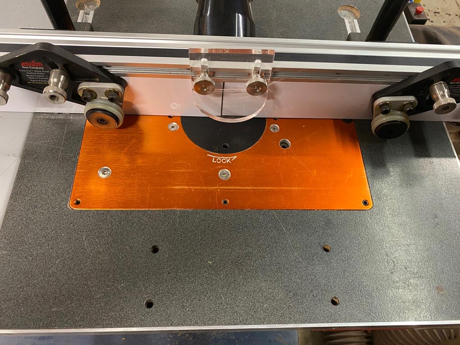
I have seen a number of router tables, but the one that I found that might suit my needs is the one on Hooked on Wood (minus the incra fence) which looks like this:
1691348827619.png

The fence will be a quickly removable one that uses the mft holes to locate - still to be designed.
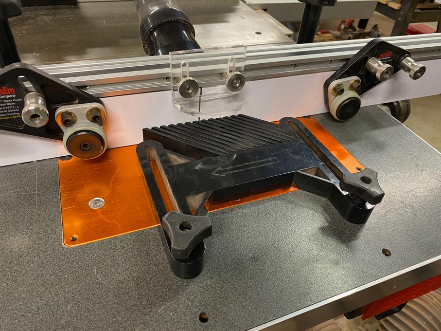
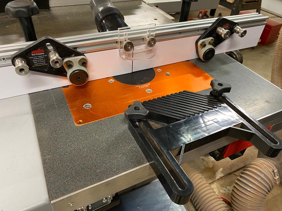
Even most other tables such as incra and UJK that I have seen have the router plate offset to one side (or the tables are very small) and have the mitre track on the shorter side (see below)
1691349008270.png


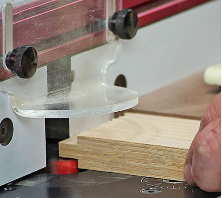
I am also planning on using Matchfit dovetail grooves for overall clamping and assembly convenience (see image below)

1691350046576.png


What am I confused about?
1. Does this kind of setup shown in the first image hinder routing the shorter edge of a long workpiece (say, creating a tenon on the end of a long stretcher, workbench legs) using a mitre fence?
2. Is there an obvious reason I am missing why most router tables have the mitre track on the shorter end (B side of the router meridian shown in the sketch below)?
3. Is it better having the mitre track on the other side of the router plate (A side of the router meridian shown in the sketch below) if I am going to be using the table predominantly facing the longer edge of the table as shown in the illustration below? (Position 1 gives me more MFT space, however, in my limited thinking I feel position 2 gives me better usability of the table overall)
4. As I shared earlier, I plan to use the MFT holes on most of the table surface but also criss-cross it with Matchfit dovetail grooves - Is this a terrible idea / overkill / sensible? - Has anyone on here done anything like this that I can ask for your experience?
5. Has anyone used the Matchfit dovetail tracks as a mitre track for a table mounted router?

1691349290057.png


Position 1 shows the conventional mitre track position.
Position 2 is my proposed position for the mitre track
The top end of the table is against a wall, even though the router table can be moved as it is on castors, this will be the position it will remain for majority of the time.
On the right hand side of the table is a door into the house, so technically I can stand and use the router by standing there (hence the dotted user figure), but I'd prefer to use the router facing the long edge.

Apologies for the long post, but I'd really appreciate a response. Please let me know if my questions are confusing :)

Best,
bp
 
My thoughts / questions.

What are you going to use this for ?

Is it mostly for putting a moulding along the long edge of things like skirting boards ? If so, you are better feeding from the short end of the table and having as long a length of table and fence as possible guiding the work and stopping the ends from drooping as you feed in and out.

Are you going to use it to (say) cut tenons on the end of furniture components or ?
In that case, put the fence close to one short end and the router near to it. Have as much table length as possible to support the body of the component, stop it drooping. That works with your preferred design but get the router and fence well over to the right. Position 2 would be good for the mitre track.

If you are going to do both, say using a table to make shaker style cabinet doors using loose tenons compromise and stick the router in the middle and make 2 fences so you can use it either way round. MFT holes will help this adaptability.

If you are going to use the table to rout housings across the bulk of a board (say for shelving units), don't bother. Sit the router handheld on the board and use a guide rail.

Take the small item to the big one.
Don't try and move a big board over a small router table any more than you would feed an 8x4' sheet over a hobby tablesaw.

HTH
That makes a lot of sense, @Sideways , thank you very much.
I think I will roughly layout the bits on the top - before making any cuts, and see what makes the best sense.
 
4. As I shared earlier, I plan to use the MFT holes on most of the table surface but also criss-cross it with Matchfit dovetail grooves - Is this a terrible idea / overkill / sensible? - Has anyone on here done anything like this that I can ask for your experience?

I have a similar groove/hole setup, and it works well, but the addition of a grid of grooves produced noticeable sagging in the - slightly oversized - MDF top, which then needed bracing from underneath. If you don’t have access to all sides of your bench you‘ll probably need to widen the slots at the edges just enough so you can drop a clamp into it from above, rather than slide it in from the side, if that makes sense? I know the Microjig stuff has its fans - @Spectric - but having had it on my bench for about 10 months I’m not convinced of their utility over, say, a regular t-slot that accepts a guiderail clamp.

Fair enough; I’m a tracksaw guy with lots of clamps and rails, and having one pair of clamps that are incompatible with everything else (and slots in the bench that only work with those two out of the many clamps I have) is a major pain-point, for me, though I appreciate not everyone is in that position.

The Microjig Matchfit clamps and router bits are all of excellent quality, and work well at what they do, but when it comes to replacing my MFT top I think I’ll be trying regular t-slot instead.

HTH P.
 
but the addition of a grid of grooves produced noticeable sagging in the - slightly oversized - MDF top, which then needed bracing from underneath.
I think having an oversized top would definately need bracing, I am using smaller tops that sit on my actual workbenches and a larger 800 by 1000 that sits on my table saw that is used with holes and just a few slots which is used with a track for cutting sheet goods. I find the slots and holes work well because the dogs provide alignment and slots quick clamping. The biggest issue is keeping the slots free from debris, but with the slots and a home made fence you can align to any angle. My slots and dogs have now been used on a face board for my woodrat, again the dogs provide support and alignment whilst the clamps hold the work in place. My issues with the slotted track is cost, and it can be jacked out if not used correctly as there is not a lot of wood in which to screw it and it has to be flush rather than below the surface of the top.

Another bonus I have found is that when making an mft top, if you put the slots in first then when drilling the holes with the Parf system you can clamp it with the microjig clamp which I find gives better fitting holes as there is NO movement in the drilling guide.

This video is worth a watch

 
I have a similar groove/hole setup, and it works well, but the addition of a grid of grooves produced noticeable sagging in the - slightly oversized - MDF top, which then needed bracing from underneath. If you don’t have access to all sides of your bench you‘ll probably need to widen the slots at the edges just enough so you can drop a clamp into it from above, rather than slide it in from the side, if that makes sense? I know the Microjig stuff has its fans - @Spectric - but having had it on my bench for about 10 months I’m not convinced of their utility over, say, a regular t-slot that accepts a guiderail clamp.

Fair enough; I’m a tracksaw guy with lots of clamps and rails, and having one pair of clamps that are incompatible with everything else (and slots in the bench that only work with those two out of the many clamps I have) is a major pain-point, for me, though I appreciate not everyone is in that position.

The Microjig Matchfit clamps and router bits are all of excellent quality, and work well at what they do, but when it comes to replacing my MFT top I think I’ll be trying regular t-slot instead.

HTH P.
Really appreciate the response, @petermillard .

I understand what you meant about the dropping the clamp in.

And I will also be bracing the underneath of the table to avoid /minimize sagging.
 
I think having an oversized top would definately need bracing…
It’s 800mm deep rather than the 718mm of a regular MFT/3 Roy, and it was fine before I put the slots in. Completely agree about things falling into the grooves - pencils are especially annoying, and cables can also snag on the edges.
 
It’s 800mm deep rather than the 718mm of a regular MFT/3 Roy, and it was fine before I put the slots in.
Is your top supported or is it like the original where it sits in a frame round the edge ? On mine I use backing strips of MDF underneath and between the holes so really backing the slots and without these I would think a little sagging would occur.
 
Unless the router fence is held perfectly parallel to the mitre track, the combination will not be capable of accurate edging.

On my router table I do not use a track at all.

I drilled and tapped four bolt holes in line with the centre of the table ...

NoMitreGaugeTrack_html_1bb23c97.jpg


The feather board can slide back-and-forth when bolted this way. It can reach to the fence ...

NoMitreGaugeTrack_html_m4070e2b4.jpg


The forwards holes are where a mitre track would go. This is as far back as it would extend if in a mitre track ...

NoMitreGaugeTrack_html_352ef87e.jpg


The second reason for a mitre track is to use a mitre gauge to either rout out tenon cheeks, or joints such as cope-and-stick frames or box joints. There are alternate solutions for these.

To make a tenon cheek, or cope the end of a stretcher for a cope-and-stick joint, simply use a backing board against the fence ...

NoMitreGaugeTrack_html_m3a7494a7.jpg


Regards from Perth

Derek
 
@Derek Cohen (Perth Oz)
Kinda thought you'd be the type of guy to find an excuse for a miter slot,
since I don't recall you owing a spindle moulder, and guessing you might have a
fairly good mitre guage what would suit for the job.
Well, that simplifies matters!
Thanks for sharing your thoughts.

Tom
 
After valuable responses from everyone here, I have decided to do it as shown below:
1691502839228.png


1. Omit the mitre track (one less area to route and fit and gain some more space) - Use a combination of router fence, backing board and the Matchfit board to cross cut things.
2. Brace the top lengthways and widthways to fully support from the underside.

As a result, made a start!
20230808_131943.jpg
20230808_131949.jpg
20230808_134011.jpg
20230808_134019.jpg
20230808_135604.jpg
 
Looking at this image

1691509362616.png


For the holes to be on a 96mm grid it looks wrong as that ruler is next to the other one and not with the pin through both rulers. I assume you did use the 3 4 5 rule to get the holes square.
 
Looking at this image

View attachment 164168

For the holes to be on a 96mm grid it looks wrong as that ruler is next to the other one and not with the pin through both rulers. I assume you did use the 3 4 5 rule to get the holes square.
Ha ha, yup, it looks that way because I took the photo after I had drilled the holes on the rule on the left. Yes, I did follow the 3, 4, 5 method.

This was when I was drilling the second row of holes with just one rule as I already had the reference :)
 
Back
Top