New roof rafters

UKworkshop.co.uk

Help Support UKworkshop.co.uk:

This site may earn a commission from merchant affiliate links, including eBay, Amazon, and others.

johnfarris

Established Member
Joined
18 Feb 2012
Messages
129
Reaction score
2
Location
In me garden shed
Hello Folks
I need to sister new common rafters along side existing ones and i am a little unsure on how to
configure it. The new rafters are 47 x 150 and the existing are 50 x 100m. If i cut a birdsmouth to suit the plate i would be taken more than a third out the rafter which obviously is a big no no. So do i move the plate forward to get over this? The pictures show some offcuts i used to figure out how much the plate would have to move forward which is exactly 80mm

Any suggestions, comments welcome


New rafters.jpeg
 

Attachments

  • New rafters.jpeg
    New rafters.jpeg
    1.1 MB
  • New rafter a.jpeg
    New rafter a.jpeg
    1.1 MB
  • IMG-20200731-WA0015.jpeg
    IMG-20200731-WA0015.jpeg
    931.8 KB
Who has told you to do the job, and who has sized the new timbers?

A birdsmouth only exists so that the rafter can extend past the plate and form the eaves overhang. If you don't need to form an overhang, you don't need a birdsmouth, and can just extend the seat cut for the whole width of the rafter. However, there may be something else going on here, which is why I ask about the design/ designer of this work. It is curious that the plate in the photos is sitting on top of joists, rather than a wall, and that makes the "truss" incomplete. In other words, I can't see anything tying this roof together. Are there principle trusses and purlins, then? And if there are, how would sistered rafters work?
 
Hello Mike drawing and calcs have been drawn up by a design professional that i have lost all faith in.
Thinking about it I do not need to form an over hang as the existing rafters are staying and will continue to support the facia and soffit.

The new rafters will be supported by a dwarf wall sitting on a steel beam at the lower end of roof and also tied with collars. Apparently purlins that are in at the moment will not be needed. Their are no principle trusses. The pole plate the rafters are sitting on at the moment are sitting on 50 x 100mm ceiling joists. These ceiling joists are being supported by under slung joist hangers off steel beam.
 
I’ve nothing to say that Mike already hadn’t put better than me (I was going to say the whole thing looks odd)... but on people who do drawings one of my colleagues says “anyone can draw a picture, I need a engineer to make it work” he mainly says that in an exasperated way, on “special” occasions

Are you in the midst of a complex restoration? The whole setup sounds complex

Aidan
 
TheTiddles":toy0gf5c said:
I’ve nothing to say that Mike already hadn’t put better than me (I was going to say the whole thing looks odd)... but on people who do drawings one of my colleagues says “anyone can draw a picture, I need a engineer to make it work” he mainly says that in an exasperated way, on “special” occasions

Are you in the midst of a complex restoration? The whole setup sounds complex

Aidan
What makes it complex is the lack of information in the drawings. I specifically requested at the very beginning to the Architect that i didn't just want drawings that would pass building control but i wanted working drawings that would give me all the details i needed and i was willing to pay for that extra detail.

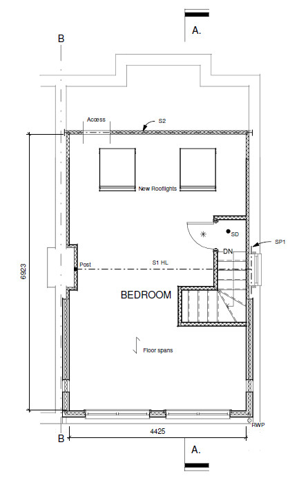
Here is an example of the drawings and specs. The opening for the staircase was to small I did not find out until i had put half the floor joists in. In hindsight I should have checked the drawings at the start, you live and learn. As you can see on the drawing nothing on their detailing how to deal with the pole plate, hence my original question. I will go back to the Architect and ask him what to do as well as doing my own research.


Spec.jpg
Section aa.jpg
Section a.jpg
 

Attachments

  • Section a.jpg
    Section a.jpg
    39.4 KB
  • Section aa.jpg
    Section aa.jpg
    48.5 KB
  • Spec.jpg
    Spec.jpg
    20.4 KB
  • IMG-20200724-WA0010.jpeg
    IMG-20200724-WA0010.jpeg
    1.2 MB
A 1:50 section is not a lot of use to anyone. Ask for a labeled 1:20 section. And careful of that stair. Without the min 50mm going at the turn, it doesn't work.
 
I'm not suggesting this in your case but unfortunately as in all walks of life there architects who are excellent and those who are hopeless.
I've had dealings with a lot of the former but also several who really shouldn't have been practising. One of those after a fraught experience on a job he was involved with where I had to rectify his mistakes I was later offered another sizeable lucrative project but when I inspected the plans closely saw discrepancies and realised it was him again I turned down the work, a difficult decision as the customer was a friend. The decision however turned out to be a good one because the job turned out to be a pigs ear with building control issues and the builder had a major fall out with the architect.

The major issue with another one was on a grade 2 listed building I was about to convert and huge errors on the plans cost a delay of 2 months in starting as the LA wouldn't accept them due to the errors and would it have been much more if I hadn't re drawn sections of the plans myself. That was 2 months of reasonable weather wasted and we ended up working under tarpaulins. My customer was a regular who I did a lot of major work for and it was so bad he ended up refusing to pay his invoice and sending him a counter invoice for extra costs incurred.
 
I'm wondering if someone can give me a bit of advice on rafter size please. I've tried contacting our structural engineer but he's on holiday for a week and I had a sleepless night last night!
I'm converting some old Victorian brick stables and was about to place an order for the new rafters when I noticed on the calculation sheets what I'm hoping is a mis-calculation, even though it was inspected and approved by my local building control officer.
I live in the UK (Midlands) and our house is 130 metres above sea level. The 45 degree pitch roof will be covered with Rosemary tiles and will be plasterboard-lined underneath. Our Structural Engineer has calculated our total max roof loading at 1.2kN/M squared. His specification is to "provide 47 x 175 C24 timber rafters at 600mm centres spanning from ridge to eaves". I was actually planning to beef this up to 47mm x 200mm at 400mm anyway to accommodate 150mm of insulation and a 50 mm air gap and I would also be prepared to reduce the centre distance to 300mm if necessary.
HOWEVER!! On the same page the structural engineer also says "Maximum span for 47 x 175 = 2.5metres" and unfortunately all the rooms in the building are between 5 and 6 metres wide (outside wall to outside wall) so 2.5 is way too short. The whole point of the exercise (steel ridge beams etc) was to get rid of purlins and to avoid using attic trusses.
Looking at some rafter span tables it appears that if the load was no more than 1.2kN/m then 47 x 195 rafters could span up to 4.81 metres which would be fine. Is our structural engineers estimate of 1.2kN/m correct or overkill?
Thanks very much for any constructive (pun deliberate) advice you can offer.
 
Would have thought 50 X 200 on 400mm c-c would be fine.

What's the weight of the tiles per square m?

Greater importance is how are you tying the walls together? beams at intervals? Steel stays?

If building control are involved, I would just run it past them. They will know what they want. Keep them onside and they can be a good information source!

Cheers James
 
Thanks for the reply James. Rosemary tiles weigh in at approx 70 kg per square metre. The roof will have a steel ridge beam with calcs supplied & approved by building control so it's the span between the ridge and outside walls I'm concerned about. I've come across the same chart which our Structural Engineer used, but extended to show increased timber sizes. It appears that, with a load of 1.2kN/m a 220 x 63 would be required.

Re tying the walls together, because it's a 1.5 storey building there is nothing which spans the full 6 metre width (beams spanning from wallplate to wallplate would be at chest height). There are dividing walls at intervals but these are not evenly distributed throughout the building. I am wondering whether our structural engineer should have designed a skeleton of steel rafters from the ridge to the wall plate.
I will check with building control as you suggest.
6.4.8 Timber joist spans - NHBC Standards 2021 NHBC Standards 2021 (nhbc-standards.co.uk)
 
My advice is you wait for your SE to come back, he's the person that is responsible, plus the tables you link to, as far is can see, are for floor joists not roof rafters, there must be more to this.
 
Yes, we're looking forward to being able to move in. The pictures were obviously taken before we removed the roof. I'm now having to make some 'roofless' decisions!!
 

Attachments

  • Pic 3.jpg
    Pic 3.jpg
    124.9 KB
  • Pic 1(A).jpg
    Pic 1(A).jpg
    121.9 KB

Latest posts

Back
Top