dual extractor design + cyclone install

UKworkshop.co.uk

Help Support UKworkshop.co.uk:

This site may earn a commission from merchant affiliate links, including eBay, Amazon, and others.

kityuser

Established Member
Joined
12 Jan 2003
Messages
1,108
Reaction score
0
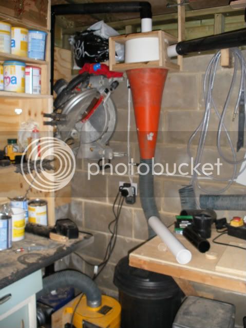
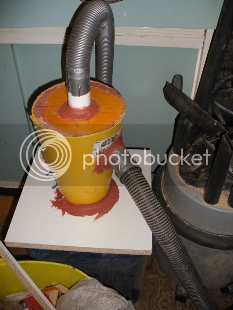
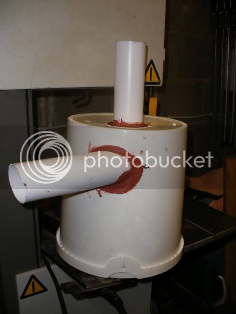
I'm trying out a few ideas with my proposed dual extractor system.

Image066.jpg


I'm thinking I've made a prize cock up here........

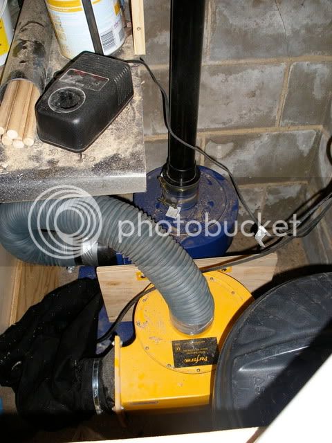
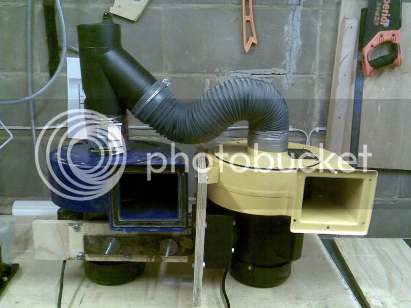
turning the yellow motor on results in a pleasing amount of suction and a good exhaust strength.

However turning the blue motor on results in a reduction of suck from the yellow one by about 80-90% i.e. hardly any suck down the flex pipe.

Now I think I can explain it, from my distant past physics day I can remember that " an increase in fluid flow results in a reduction of pressure AT THAT POINT", SO at the "y" piece the yellow extractor is effectively sucking vacuum........

My question is this:
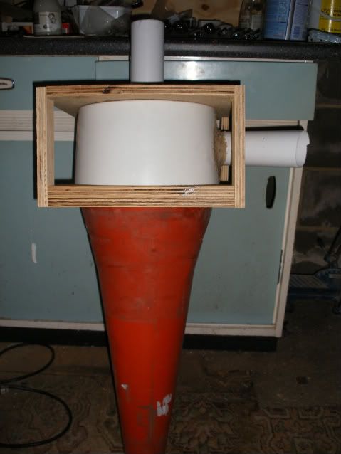
if you exagerate this effect, say connect both extractors together end-2-end then both will be trying to suck vacuum (from the other motor).
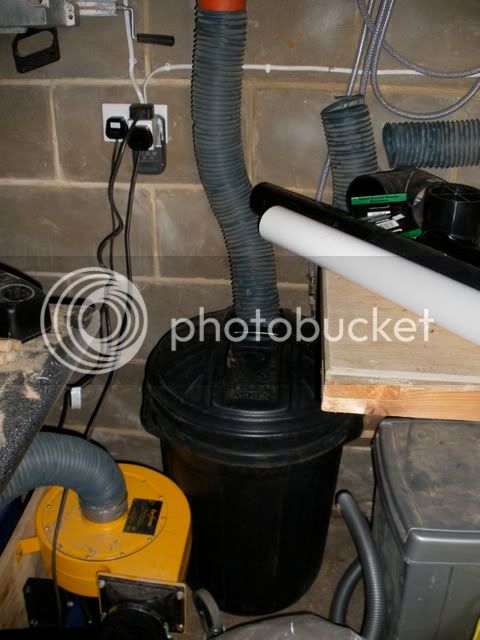
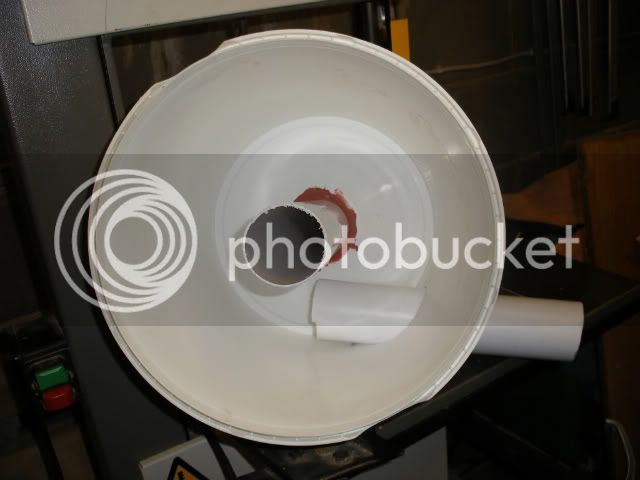
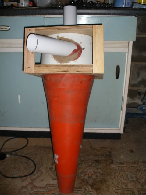
If we bring the junction round to 90 degrees, then past to where we are in the picture then we see the effect observed. If we continue round and reduce the angle to 0 degrees using a true "Y" piece i.e. a junction where the 2 air flows join exactly parallel:
2port.jpg


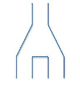
would this solve my problem?

Steve
 
No the stronger one will always be starving the weaker. (trying to suck air in reverse through it)
The only way to use the power of both fans is to put them in series not parallel, but you will need to increase the input hose to 150mm+ if you are to avoid starving the fans.
 
I know nothing about fluid dynamics but it would seem fairly likely that in order to maximise airflow, the "common" pipe to which the 2 are connected should be at least equal in cross section to the sum of the 2 individual inlets.

HVLP extractors only work well when moving the maximum amount of air, what you have done there is to effectively halve the inlet size of the 2 extractors.
 
You need to throttle the intakes to the pumps proportianally to their output, for instance, if they were identical you would want to make the ducts running to them the same so one wasn't disadvantaged, however, with one more powerfull than the other you will need to increase the resistance to the more powerfull pump so the volume air flow is balanced between the two or one will try and pull air through the other. This sounds like a lot of effort, if they are impellers and not blowers then putting them in series will be the easiest option, it will give you increased pressure and a little increase in flow, though your ducting to the machines could screw this all up.

Aidan
 
are you really going to notice that much of a difference? Seems like a lot of work to me. Why not just have 2 separate extractors going to 2 separate 'zones'?
 
Image067.jpg


This was the second attempt today. I`ve fired both of them up and the good news is there is a HUGE increase in suck when the second yellow extractor is powered.... a good start.

I connected up my current meter in line and started to test the system.

I measured the following:

blue | yellow
-------------------
on.....|.....off
2.16A |.....x
-------------------
on.....|.....on
2.19A |.....x
-------------------
off......|.....on
x........| 2.90A
-------------------
on......|.....on
x........| 2.94A

Both extractors on give me a current draw of 4.92A with no appreciable difference in tone or volume from each with the other on or off.

when I stick my 100mm to 63mm reducer on the 4.92A reduces to 4.76A with a slight increase in tone from each. I presume they are being starved slightly. However the suction from the end of a 2 meter length of 63mm drain downpipe is immense :twisted:

I know that reducing the bore is not going to be the most clever of things, but I`ve got an abundance of fittings and piping for wickes 63mm downpiping.....

Steve
 
That looks really good, I think I may follow your lead at some point as those types of extractors are cheap to pick up now!
 
continuing with the general topic of dust extraction, I've been working on my main cyclone yesterday:

DSCF3501.jpg


DSCF3502.jpg


has now turned into this mock up, needs bolting spraying and tidying:

DSCF3749.jpg


DSCF3748.jpg


I've kept the 63mm inlet and outlets as I plan on using the same size for the rest of the system. The cone was spotted on a walk with the dog at a local woodland walk, found a ranger and asked if I could have it and was to to help myself, the ultimate recycling :)

Still to do is an air ramp for inside, the plan is to vent the bottom into a black garden bin that I got from ebay for £2 via some 100mm flexi-pipe.

Steve
 
Nice one-look forward to more progress shots . And great use of the traffic cone :D
 
When you say "black garden bin" are you talking plastic? If so, aren't you concerned that it could collapse? There have been comments to this effect on other posts recently.

Edited to correct typo's!
 
Still looking good, I'd love to know how powerful it is, but I guess there is no way of you measuring it.
 
Chems":28ase07y said:
Still looking good, I'd love to know how powerful it is, but I guess there is no way of you measuring it.

funny you should mention that.
At present I only have the current being drawn by the blowers to gauge any effect I have on teh suction.

I`m thinking of constructing a suction meter, basically a spring scale mounted inside a section of tube with a tighly fitted/gasketted plunger.
The more suck, the more the plunger is drawn in, and the more the spring scale gets deflected/stretched.

In terms of how powerfull the blowers are, turning the second one on with the first already spinning causes a HUGE increase in suck. You can actually hear the effect........ (from the end of the feed pipe).

I`m keen to develop a more accurate metric for assessing the performance so i can debug various scenarios, without the cyclone attached, with it attached with no inlet feed, and finally with 10 foot or so of 63mm attached to the cyclone inlet.

I`m guessing (and from what I`ve read) that 63mm pipe will starve the blowers somewhat, but like I said I have quite a supply of fittings and pipe already in that diameter.
I`ve tried to make the system "modular" i.e. I can break the top off of the cyclone, incase in future I want to upgrade the bore of the system for say 100mm

as for the garden bin, yes its a plastic black round type (80 litres I think).
if It colapses then I`ll try the strengthen it with some ply ribs, otherwise I`ll got to plan B which is to get a wheely bin.

things are moving a bit slowly this week as I'm on holiday......

hopefully I`ll hit the ground running and have some more pics by the end of the week.

Steve
 
I'm sure you could buy a cheap air flow type thing, even a wind-meter that you put in front of an inlet, or make a little box that you could put the wind-meter in with an in and an out section and measure the windspeed.

I guess the brilliant thing about the cyclone is you can use a HVLP type extractor for fine dust?
 
hooked the cyclone up tonight:

DSCF3894.jpg


The chop saw is going to be re-homed and the cyclone situated right into the corner.

Here is the garden bin:
DSCF3891.jpg


When on the suck is such that removing the garden bin lid is impossible.
Here is the mock up piping to the blowers:
DSCF3892.jpg


and the blowers will live at the end of my worktop
DSCF3893.jpg


should make quite a nice addition to a wasted corner.

In operation I'm very impressed. LOTS of holes to plug... lots of air leaks, but hey... it was only a mock up to check the system before I do a belt-and-braces install.

I sucked up about a 1/2 bucket full of mixed dust/shavings/waste. One thing I noticed is some of the waste can stay in the cone for quite a while, you can hear it cycling round accelerating as it decends the cone :wink:


and of course I haven't installed the air ramp yet.
Next job is to break it all down, install the missing bits and seal everything. Then install in the corner.
I'm thinking at the moment to plumb in to the centre of the workshop (a central down pipe hung from the ceiling) and have a decent size flexi hose which I'll attach to each machine as and when they are in use, rather than pipe to each machine with a blast gate.

quite a bit of talc got through to the bag on the final blower, however I'm not worried because I know the route cause of this CAN be air leaks. Also a little talc is to be expected (as with my vac cyclone).

chuffed at the mo.....

having a beer....
Steve
 
kityuser":3nsylig7 said:
(as with my vac cyclone).

Steve

Did you do a thread on your Vac cyclone?

I'd very much like to make one myself and I'd be grateful for any design info/advice, dimensions etc.

I've done a search but can't find anything.
 
this thread
https://www.ukworkshop.co.uk/forums/view ... c&start=30

morphed into my mini vac cyclone build.

It was a rip off of the dust deputy
http://www.dustdeputy.com/

ok, not pretty but BLOODY hell does it work!

here is that latest piccy I have:

DSCF3530.jpg


its all rubbed down, sprayed and finished off now.
It was my intention to scrap this mockup and make a glass fibre version (as I have a mate in the trade), but it works so well I don't think I'll bother.

The dimensions are:
10 inches high
7 inches diameter at the top
4 inches diameter at the bottom
40mm waste pipe for inlet and outlet ports
outlet decends 4 inches into cyclone from top.
inlet port enters the side 3.5 inches on centre.

Steve
 
Steve
Hows it go with the black garden bin? mine just kept imploding if the inlet tube got a few too many shavings in and thats using a 1250watt vac :? .
When I get the time I`ll knock up a smallish mdf/ply bin just big enough to fit a black bag in.
Cheers
Steve
 
Hi Steve,

I'm looking at this cyclone business too and I've got a road cone. I was just thinking about your idea to build a box and put a bin liner in it. Would the bin liner get sucked up into the cyclone bit?

Brendan
 
Steve, very interesting indeed.

A couple more questions:

I notice that most cyclones (icluding your big one) have the inlet and outlet ports fitted in a parallel sided section on top of the cone. Any particular reason why you didn't follow this practice?

Your final dimensions are slightly different from the original proposal (10" high v. 12" and bottom dia 4" v. 3.5") any particular reason for this?
I'm interested in this because in several other places I've come across comments regarding the height v. diameter ratio (1.6 or 1.64) and your original 12" dia. (1.71) seems to be much closer to this than the final 10" dia. (1.43).

What do you mean by "inlet port enters the side 3.5" on centre"?

Has your bucket shown any signs of collapsing under the suction?

Providing that other members of this forum have left any out there :lol: , I think I might try this using a road cone either fitted into a plate like yours, or more likely I'll fit the cone in the top of a ply or mdf cabinet with a removeable bucket inside. I'd have the cabinet door hinged and sealed with draught excluder which would eliminate any leakage problems.

Any comments would be greatly appreciated.

PS; i need to find out about this air ramp business - I can't understand most of the descriptions I've read. Any idea where I can find a photo?

In pumping plants they use cyclones for 2 applications - bloody great big ones (I've seen them nearly 10ft high) for sand separation on the outlets from borehole pumps and tiny little ones to eliminate solids from gland sealing water. I've just looked at a sectional illustration of one of these little ones and the bottom of the outlet pipe seems to be immersed into a central cone within the main cone. Would this effectively be performing the same function as the air ramp?
 
Back
Top